

Page 1
SBSKITB
Side by Side
Instruction manual
Page 2

2
Important information
• Do not install the unit on your own or have unqualified personnel install it.
• Improper installation may result in damage, malfunctioning or risk of electric shock.
• This Side by Side unit must have the cooler section on the right side and the beverage storage/freezer
section on the left side; the positions are not reversible.
• The power cords must be connected separately to a suitable socket.
• All information regarding each section of this equipment is given in the user instructions to be found inside
the cooler section. Please read the instructions carefully before carrying out any operation.
• Removal and reinstallation of this unit must only be carried out by authorised personnel.
• Please keep these installation instructions for future reference or further installation.
Page 3

3
Tools required for installation
(not supplied)
HAMMER
T
SCREW DRIVER PHILIPS 2
U
SCREW DRIVER WRENCH 7 mm
V
WRENCH 13 mm
W
WRENCH 24 mm
X
Y
SET SCREW WRENCH 4 mm
LEVEL
Z
Page 4
4
Page 5
5
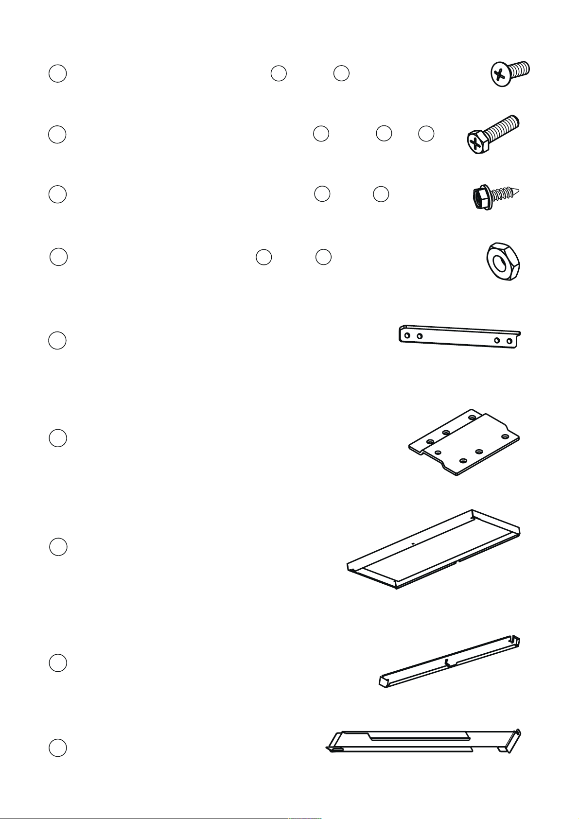
CUPHEAD SCREW M5x12 (bag 1 ) TOOL U
1
HEXAGON-HEAD SCREW M5x18 (bag 2 ) TOOL V OR U
2
HEXAGON-HEAD SCREW 4.2x13 (bag 3 )TOOL V
3
HEXAGON NUT M8 C15 (bag 4 )TOOL W
4
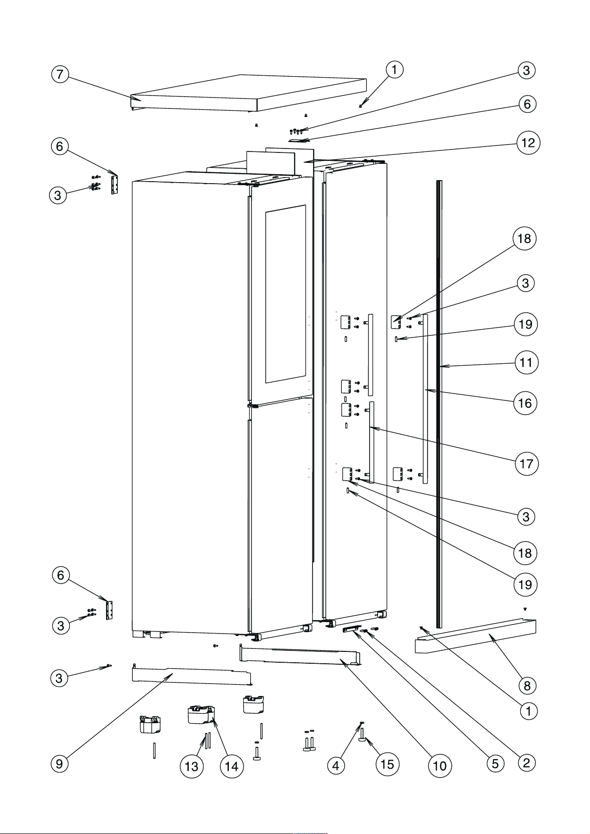
CONNECTION BRACKET
5
UPPER CONNECTION BRACKET
6
TOP PANEL
7
PLINTH
8
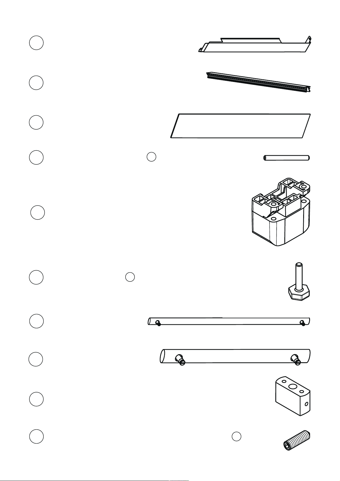
9
LEFT SIDE
Page 6
6
10
RIGHT SIDE
MAGNETIC GASKET
11
SPACER SPONGE
12
REAR FOOT PIVOT TOOL T
13
REAR FOOT
14
FRONT FOOT TOOL X
15
HANDLE ASSEMBLED
16
COOLER
HANDLE ASSEMBLED
17
WINE/FREEZER
MOUNTING BLOCK
18
19
SCREW M6x20 HEXAGON SOCKET CONE TOOL Y
Page 7

7
• Carefully place the unit on the floor, following the instructions on the packaging to make sure the unit is
facing upwards.
• Open the bottom part of packaging and remove the corner protection.
• «A» Screw the M8 nuts (bag «4») on the respective front feet.
• «B» Screw the front feet on the bracket of the unit using the dimension indicated in fig. «C».
• «C» Position the rear feet on the compressor support plate.
• «D» Insert the pin, using a hammer, so that it does not protrude outside the foot.
• Carefully reposition the appliance in the upright position and remove completely the packaging.
• Operation to be carried out on both units.
A
B
40mm
C
D
Page 8

8
• Glue the spacer sponge on the right side of the wine cooler-freezer, using the distances indicated in the fig.
under neath.
Right side
Page 9

9
• Bring the units near to each other.
• «A» If necessary adjust the front feet so that the units are both the same height.
• «B» Insert the bottom “L” joining bracket.
• «C» Fix the bracket with four M5x18 screws (bag «2»).
A
B
C
Page 10

10
• «A» Fix the joining bracket with four 4.2x13 self-tapping screws (bag «3») using the holes in the sides.
• The bracket must be positioned so that the side of the bracket with the hole in the centre part protrudes
as shown in fig. «A».
• «B» Fix the joining bracket with six 4.2x13 self-tapping screws (bag «3») using the holes in the sides.
• «C» Fix the joining bracket with four 4.2x13 self-tapping screws (bag «3») using the holes in the sides.
• The bracket must be positioned so that the side with middle hole is turned down as shown in fig. «C».
Page 11

11
• «A» Ensure the front feet are the same height, to level the appliance.Verify the position with a level.
• «B» Lock the M8 nuts.
A
B
Page 12

12
• If it is necessary to amend the level of the doors, or one single door, partially unscrew the hinge screws,
related to the door to be adjusted, and move the hinge as indicated in the illustration below.
• Repeat the operations for each single door until a correct alignment is obtained.
Page 13

13
• Before proceeding with the assembly of the top remove the protective film.
• «A» Position the top so that the bottom front part fits under the top hinges.
• «B» Push the top so that its rear welt is touching the back of the units.
• «C» Fix the back of the top with four 4.2x13 self-tapping screws (bag «3»).
Page 14

14
• Fit the trim “11” between the two units by pressing along the entire profile, see figure below.
Page 15

15
• Before proceeding with the fixing of the plinth “8” remove the protective film.
• Fit the plinth “8” so that the inner hook couples with the joining bracket as shown in the illustration.
Page 16

16
• Fix the front of the top and kickplate with M5x12 screws (bag «1»).
Page 17

17
• Before proceeding with the fixing of the side strips “9,10” remove the protective film.
• Insert the front end of the side strip behind the plinth, see fig.“A”.
• Align the outside of the side strip with the side of the unit and fix it with a 4.2x13 self-tapping screw “3”
(bag «3»).
• Repeat the operation for the left side, see fig.“B”.
Page 18

18
• Fit the three handles, as shown in figures A, B and C.
• The screws and grub screws are included in the handle-kit.
• Fix the two fitting blocks with two 4.2x13 self-tapping screws for each (bag «3» ).
• Insert the handle pins in the middle hole of the block.
• Secure the handle with two M6x20 grub screws.
A
B
C
Page 19

You should also ensure that air can circulate freely around the back and the top of the cabinet.
Position the assembled Side by Side:
• At least 50 mm from the rear wall.
• At least 150 mm from any overhanging kitchen furniture.
• Install the appliance.
19
Page 20

John Lewis Partnership
171 Victoria Street
London SW1E 5NN
www.johnlewis.com
2221 055-10
10/07
 Loading...