

Page 1
Please check the pack contents before attempting to assemble this product. A full checklist of components is given in this leaflet. If any components are missing, please contact your the John Lewis Helpline.
This product is HEAVY, it should be assembled as near as possible to the point of use. TAKE CARE
WHEN LIFTING to avoid personal injury and (or) damage to the product.
This product takes approximately 70 MINUTES to assemble with 2 PEOPLE.
The fittings pack contains SMALL ITEMS which should be KEPT AWAY FROM YOUNG CHILDREN.
Read this leaflet in full before commencing assembly.
If you are missing some fittings please contact our spare parts helpline on 0330 005 9435.
Opening hours are 9am - 5pm Monday to Friday.
John Lewis
Stock Code: 80319002 - 80319102 - 80319202
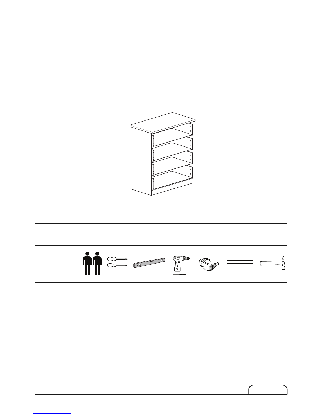
Mixit chest 4 drawers
Thank you for purchasing this Mixit chest 4 drawers. Please read the instructions carefully before use to
ensure safe and satisfactory operation of this product.
PRE-ASSEMBLY PREPARATION
Please ensure instructions are read in full before attempting to assemble this product.
Necessary Tools
Screwdriver
0
0203040506070809000020 30 40 50
0
23456
Ruler/tape
measure
Small hammer
Drill
Eye protection
Spirit level
MXT 04/13
Page 1
Page 2
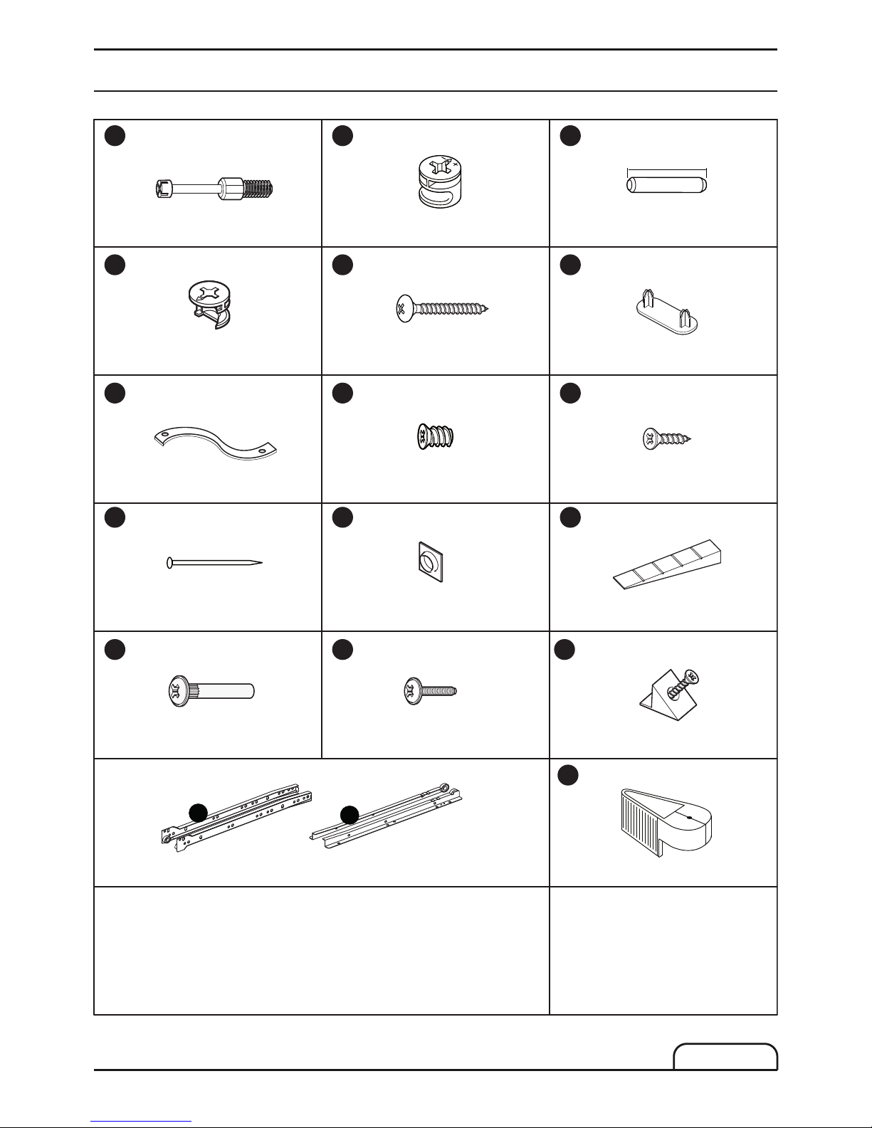
Metal dowel x 24 Long cam lock x 8 Wooden dowel x 24
30mm
Short cam lock x 16 30mm Screw x 16 Support foot x 4
Strap x 1 11mm Euroscrew x 16 15mm Screw x 25
25mm Nail x 30 Bumper x 8 Levelling Wedge x 2
Fixing block x 8
27mm Connector x 4
4MAx15 Connect. screw x 4
Pair of rollers 4
A B
C
G
L
H
M
D E
F
I
N
O P Q
Z2
Z1
Nail guide x 1
P1
Page 2
MXT 04/13
Fittings checklist
Page 3
1
2
3
4
5
6
7
x 4
8
x 4
9
x 4
10
x 4
11
x 4
Raw
Page 3
MXT 04/13
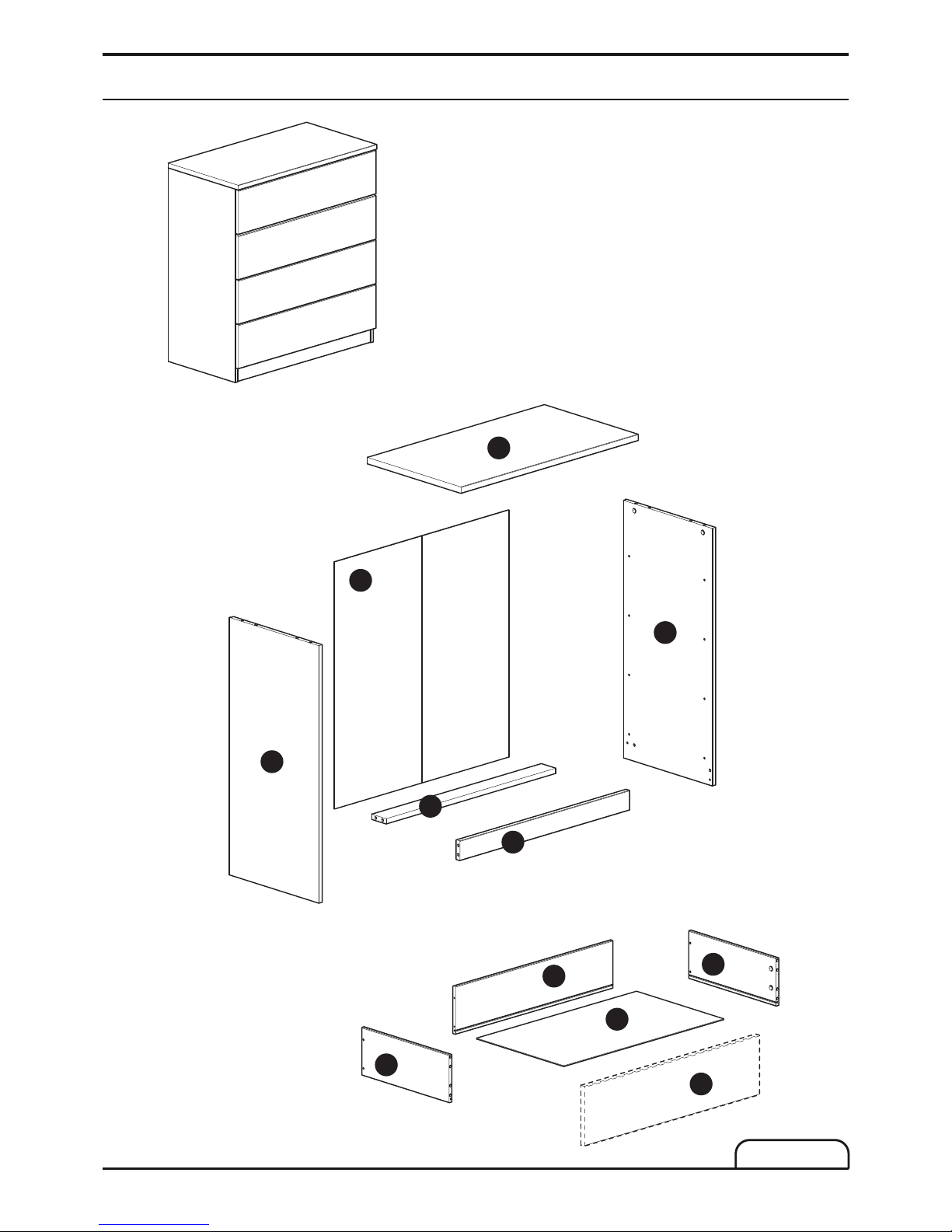
Parts checklist
Page 4
1
A
Page 4
Step by step assembly instructions
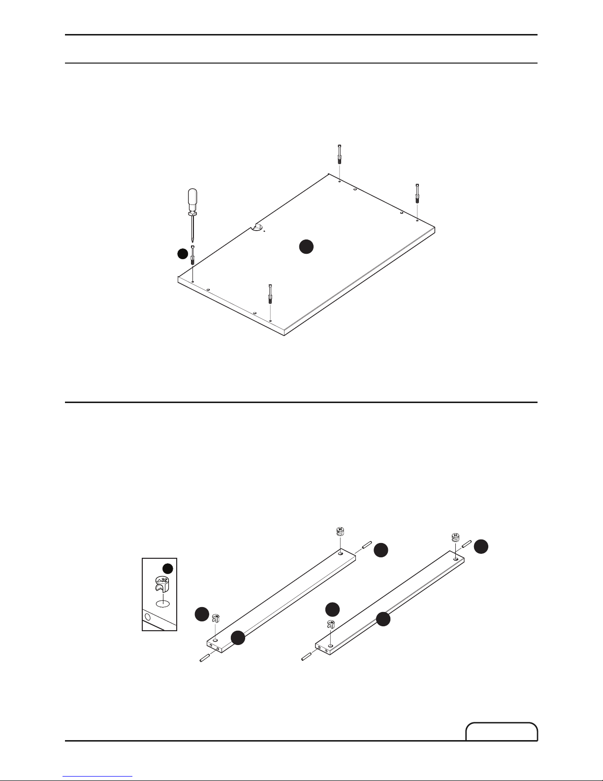
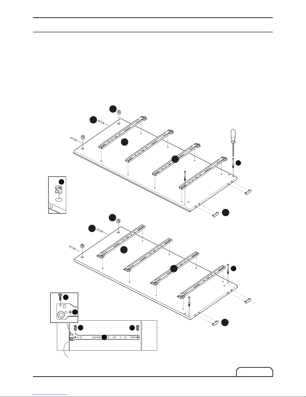
Step One
Attach 4x metal dowels (A) into the pre-drilled holes on top panel (1) as shown. Use a screwdriver to turn
fitting (A) clockwise to fix.
1.
Step Two
Attach 4x wooden dowels (C) into the pre-drilled holes on rails (5) (6) as shown.
Place the cam lock (B) into the holes on rails (5) (6) as shown, arrow pointing towards the bolt.
1.
2.
5
6
Raw
B
B
C
C
B
MXT 04/13
Page 5
B
left side
F
F
3
right side
2
C
C
A
A
B
Z1
Z1
B
Front side
H
H
I
H
Z1
Page 5
MXT 04/13
Step by step assembly instructions
Step Three
Attach 4x metal dowels (A) into the pre-drilled holes on side panels (2) (3) as shown. Use a screwdriver
to turn fitting (A) clockwise to fix.
Attach 4x support foot (F) into pre-drilled holes on side panels (2) (3) as shown.
Fix 8x runner parts (Z1) to the side panels (2) (3) through holes shown in the detail view using
16x euroscrews (H) and 8x screws (I).
Attach 4x wooden dowels (C) into the pre-drilled holes on side panels (2) (3) as shown.
Place 4x cam lock (B) into the holes on side panels (2) (3) as shown, arrow pointing towards the bolt.
1.
2.
3.
4.
5.
Page 6
12
B
A
B
2
3
5
6
Raw
12
B
A
B
1
2
3
Page 6
Step by step assembly instructions
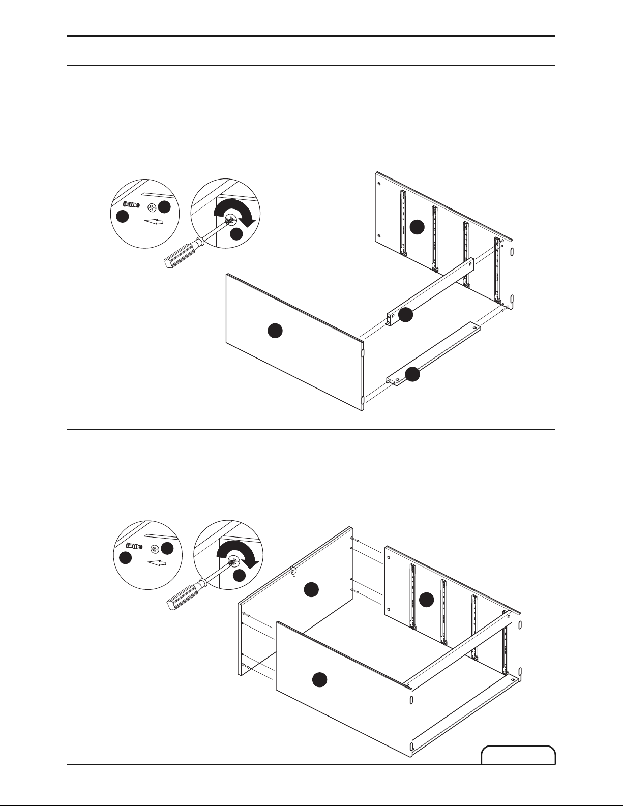
Step Four
Attach side panels (2) (3) to rails (5) (6) as shown. Ensure metal dowels (A) and wooden dowels (C) are
aligned correctly with the holes of matching parts before attaching.
Secure side panels (2) (3) to rails (5) (6) using a screwdriver to turn fitting (B) clockwise to fix.
1.
2.
Step Five
Attach top panel (1) onto sides (2) (3) as shown. Ensure metal dowels (A) and wooden dowels (C) are
aligned correctly with the holes of matching parts before attaching.
Secure top panel (1) to sides (2) (3) using a screwdriver to turn fitting (B) clockwise to fix.
1.
2.
MXT 04/13
Page 7

L
Important:
The cabinet MUST
be ‘square’ when the
back is attached.
4
L
L
P1
Page 7
MXT 04/13
Step by step assembly instructions
Step Six
Position back panel (4) as shown.1.
Step Seven
Attach back panel (4) onto back side of the unit using 30x nails (L), with the help of nail guide (P1).
1.
4
Page 8

N
N
Page 8
Step by step assembly instructions
Step Eight
With help of an assistance, carefully stand up the unit upright.1.
Step Nine
Use 2x levelling wedge (N) to level the unit.1.
MXT 04/13
Page 9
Ø5mm
P
O
Page 9
MXT 04/13
Step by step assembly instructions
Step Ten
Fittings have been supplied in order to join units together.
Place units together in their final positon.
Decide position where to drill through using a Ø5 mm bit.
Push the Connector (O) into the hole and then screw Bolt (P) in from the other side, tighten with a
screwdriver.
1.
2.
3.
Page 10

Top of Unit
W
A
L
L
W
A
L
L
W
A
L
L
G
G
G
I
1
4
Page 10
MXT 04/13
Step by step assembly instructions
Step Eleven
To prevent possible overbalancing we recommend that this unit is secured to a suitable wall by use of wall
strap (G) fitted to the Top of the unit.
Secure one end of the wall strap (G) to the wall.
Thread the other end of the wall strap (G) through the gap between the top (1) of the chest
and the back panel (4).
Working from the front of the chest, fix the wall strap (G) to the underside of the top (1) using the
wall strap screw (I).
Thread the screw through through the end of the wall strap (G) and into the pilot hole in the underside
of the top (1).
Do not fix the wall strap (G) to any other component.
! IMPORTANT !
Take care when drilling the wall that you do not drill into any pipes, wires etc. If in doubt, consult an expert.
Wall plug and screw not included.
See wall fixing guide at page 14.
1.
2.
3.
4.
5.
Page 11

G
I
N
D
A
D
D
10
x 4
7
x 4
C
9
x 4
C
D
A
D
D
9
10
11
E
E
10
x 4
7
x 4
C
9
x 4
C
Page 11
Step by step assembly instructions
Step Twelve
Attach 4x wooden dowels (C) into the pre-drilled holes on drawer sides (9) (10) as shown,
repeat for all drawers.
Place the cam lock (D) into the holes on drawer sides (9) (10) as shown, arrow pointing towards the bolt,
repeat for all drawers.
Attach 4x metal dowels (A) into the pre-drilled holes on drawer front (7). Use a screwdriver to
turn fitting (A) clockwise to fix, repeat for all drawers.
1.
2.
3.
MXT 04/13
Step Thirteen
Fit the RH (10) and LH (9) drawer sides to the drawer back (11) using 30 mm screws (E),
repeat for all drawers.
1.
Page 12

9
10
8
11
E
E
2
D
1
D
A
7
8
I
I
I
M
M
I
Z2
Z2
2
D
1
D
A
7
Q
Q
Q
Page 12
MXT 04/13
Step by step assembly instructions
Step Fourteen
Slide drawer bottom panel (8) into the drawer box grooves.
Position drawer front (7) onto drawer box, turn locking nuts (D) clockwise to lock.
repeat for all drawers
1.
2.
Step Fifteen
Fix runner part (Z2) onto the drawer using 4x screws (I)
repeat for all drawers.
Fix 2x bumper (M) as shown.
repeat for all drawers.
Position 2x fixing blocks (Q) into the groove of the
drawer back, drawer front and screw to fix.
repeat for all drawers.
1.
2.
3.
Page 13

Page 13
MXT 04/13
Step by step assembly instructions
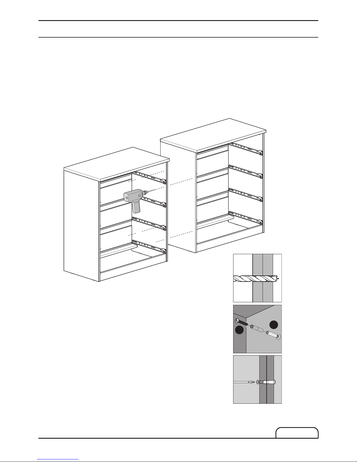
Step Sixteen
Tilt the drawer as shown.
Slide the drawer box along the runner parts until the stop.
Wheels and runner parts have to be correctly matched as shown.
1.
2.
Page 14

Wood
If xing to wood
make su re that it
isn't chipboard as
screws can easily
p
ull away from the
core structure
Brick or Masonry
Use an appropriate
w
all plug provided you
are sure your wall is
sound.
Cavity wall
Special toggle
wall plugs are
needed. Seek
expert advice.
Page 14
Wall fixing - if in doubt seek professional advice
Care and Maintenance
MXT 04/13
This product has been manufactured using modern manufacturing methods and materials. With appropriate in-home care and maintenance it will provide trouble free performances. Many domestic multipurpose cleaning agents are unsuitable for use on this product. The use of aggressive chemicals can result in
irreversible damage.
Please follow these guidelines carefully.
USE only 5% soap, 95% water solution, wiping with a damp (not wet) cloth.
Finally dry with a soft clean cloth. Dust with a soft clean cloth only.
DO NOT USE wax furniture polish, abrasive or aggressive cleaners, bleach or hypochlorate (chlorine)
based cleaners, multi-purpose cleaners, dilutes, acetone, alcohol, solvent or similar products.
Page 15

Page 15
MXT 04/13
Safety Instructions
Never drag furniture when moving it, always lift it.
Periodically check all fixings to ensure none have come loose and re-tighten when necessary.
Please take care when handling or moving the furniture as careless handling may cause damage or injury.
Furniture can be dangerous if incorrectly installed. Assembly should be carried out by a competent person. No
liability will be accepted for damage or injury caused by incorrectly installed or assembled furniture.
It is recommended that before moving a heavy object to a new location it is completely dis-assembled to avoid
personal injury or damage to the furniture. Please be careful to retain all fittings when doing this.
This product is designed to be fixed securely to a sound wall in the manner stated.
It must under no circumstances be used free-standing. No liability will be accepted for damage or injury caused by
inadequate fixing or use without fixing.
PLEASE KEEP THESE INSTRUCTIONS FOR FUTURE REFERENCE
John Lewis Partnership 171 Victoria Street London SWIE 5NN
www.johnlewis.com
 Loading...