

Page 1
JLBIHD908
Built-in cooker hood
Instruction manual
Page 2
Important safety information
It is most important that this instruction manual should be retained with the appliance for future
reference. Should the appliance be sold or transferred to another owner, or should you move house and
leave the appliance, always ensure that the book is supplied with the appliance in order that the new
owner can get to know the functioning of the appliance and the relevant warnings. These warnings
have been provided in the interest of safety . You MUST read them carefully before use or installation by a qualified person. If you are unsure of the meanings of these warnings contact the John Lewis
branch from which you purchased the appliance.
Installation
• Any installation work must be undertaken by a qualified and
competent person to the relevant National Standards.
• This hood must be installed in accordance with the installation instructions and all measurements must be adhered
to.
• If the cooker hood is installed for use above a gas appliance
then the provision for ventilation must be in accordance
with the Gas Safety Codes of Practice BS.6172, BS.5440
and BS.6891 (Natural Gas) and BS.5482 (LP Gas) 1994,
the Gas Safety (Installation & Use) Regulations, the Building
Regulations issued by the Department of the Environment,
the Building standards (Scotland) (Consolidated) Regulations issued by the Scottish Development Department.
• The fan motor of this cooker hood incorporates a cut-out
device which will operate if the cooker hood is installed
below the minimum height recommended under section
‘Clearance Height’, or if the motor becomes overheated.
If the cut-out device is activated, switch off the fan motor
and allow the cooker hood to cool. The cut-out device will
reset itself when the fan motor has cooled significantly.
• It is dangerous to alter the specifications or modify this
product in any way.
• When installed between adjoining wall cabinets the wall
cabinets must not overhang the hob.
• If the room where the hood is to be used contains a fuel
burning appliance such as a central heating boiler then its
flue must be of the room sealed or balanced flue type.
• If other types of flue or appliances are fitted ensure that
there is an adequate supply of air to the room.
• The ducting system for this appliance must not be connected to any existing ventilation system which is being
used for any other purpose.
• Do not install above a cooker with a high level grill.
Child Safety
• This appliance is designed to be operated by adults. Children should not be allowed to tamper with the controls
or play with the appliance.
• Keep all packaging materials away from children.
Use
• This product is for domestic use only.
• Never leave frying pans unattended during use as overheated fats and oils might catch fire.
• Never do flambé cooking under this cooker hood.
• Do not leave naked flames under the hood.
• This cooker hood is designed to extract unpleasant odours
from the kitchen, it will not extract steam.
Maintenance and Cleaning
• This appliance can be a hazard if the synthetic paper and
charcoal filters are not replaced as recommended.
Service
• Under no circumstances should you attempt to repair the
appliance yourself. Repairs carried out by inexperienced
persons may cause injury or more serious malfunction.
Refer to your local Service Force Centre. Always insist
on genuine spare parts.
Environmental Information
• After installation please dispose of the packaging with due
regard to safety and the environment.
• The symbol on the product or on its packaging
indicates that this product should not be treated as
normal household waste. Instead it should be taken to the
appropriate collection point for the recycling of electrical and electronic equipment. By ensuring this product
is disposed of correctly, you will help prevent potential
negative consequences for the environment and human
health, which could otherwise be caused by inappropriate
waste handling of this product. For more detailed information about recycling of this product, please contact your
local council, your household waste disposal service or
the shop where you purchased the product.
2
Page 3
Contents
For the User
Important Safety Information 2
Description of the Appliance 4
Using the cooker hood 9
Cooker Hood Controls 9
To Operate 10
Recirculation 10
Extraction 10
Maintenance and Cleaning 11
External Cleaning 11
Cleaning the Ducting panels 11
Metal Grease Filters 11
Charcoal Filters 12
To Remove/Replace Charcoal Filter 12
Changing the Halogen Spot Lamp 13
Something Not Working 14
Repairs and After Sales Service 14
For the Installer
Electrical Connections 8
Electrical Requirements 8
Electrical Connection 8
Installing the Cooker Hood 5
Installation Requirements 5
Unpacking 5
Fitting the Wall Brackets 6
Fitting the Canopy Hood 6
Extraction 7
Recirculation 7
Guide to use the Instruction Manual
The following symbols will be found in the text to guide
you through the instruction book
Safety instructions
Step by step instructions
Environmental Information
This appliance complies with the followings E.E.C. Directives:
- 89/336 (Electromagnetic Compatibility Directive)
- 73/23 (Low Voltage Directive)
- 93/68 (General Directives)
and subsequent modifications
3
Page 4
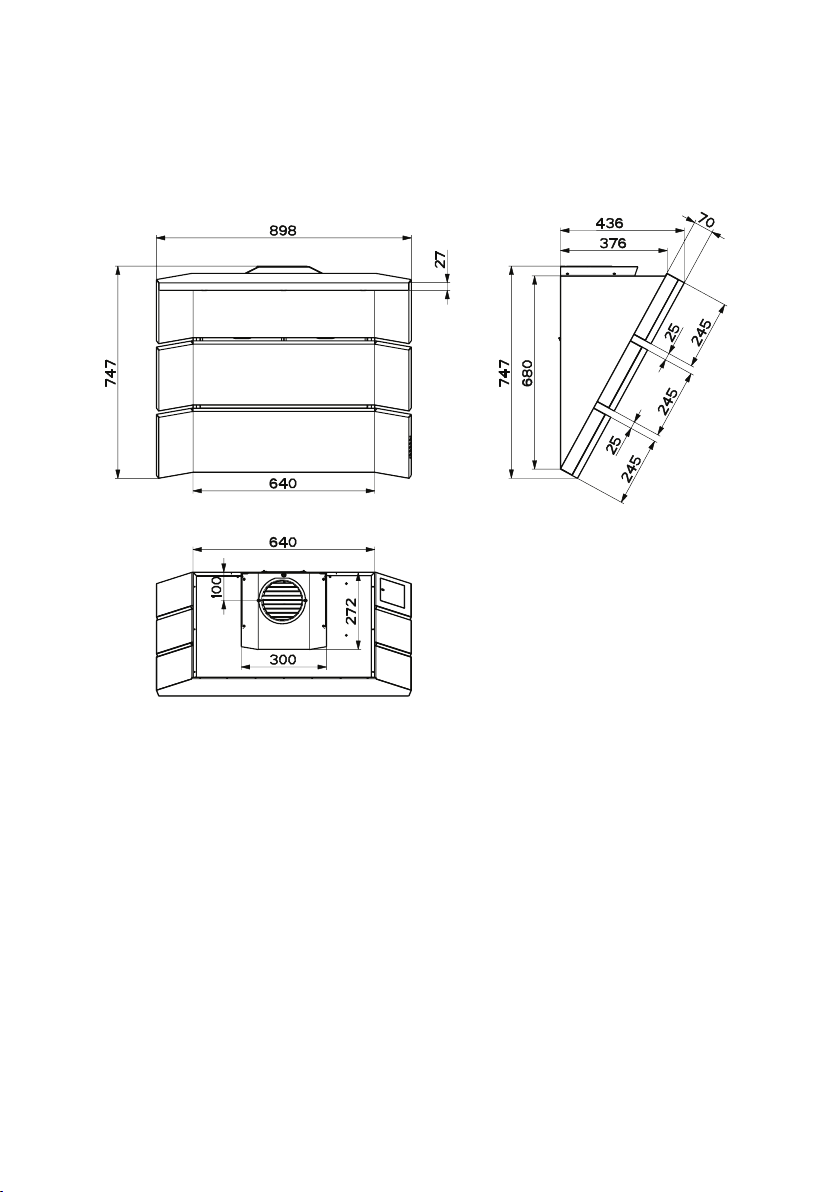
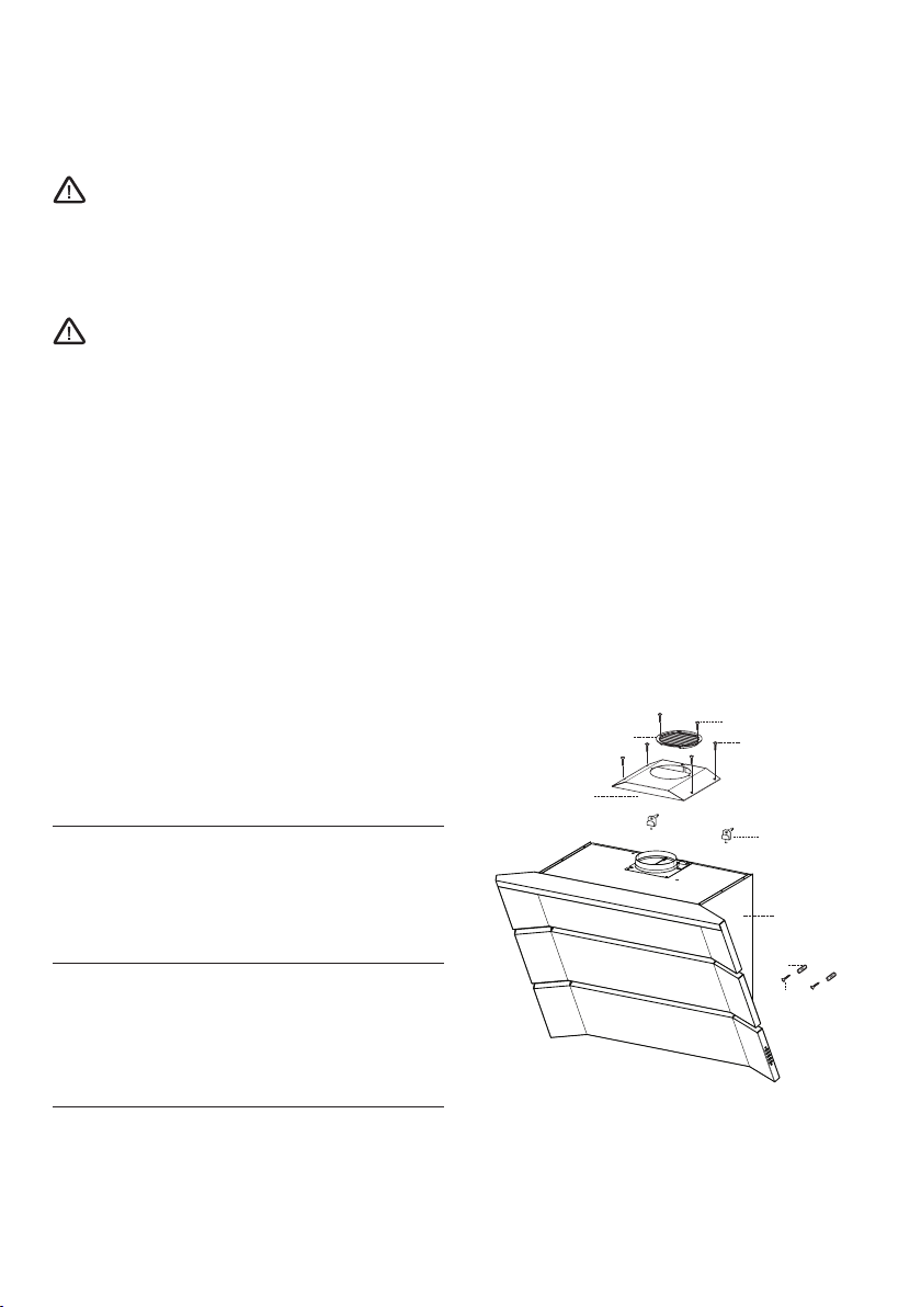
Description of the appliance
4
Page 5
Installation
Please ensure that when the appliance is installed
it is easily accessible to an engineer in the event
of a breakdown.
All installations must comply with the local
authorities requirements for the discharge of
exhaust air.
Incorrect installation may affect the safety of
this cooker hood.
Installation Requirements
Before installation check the wall to which
the cooker hood is to be fitted for electric
cables, water pipes or gas.
The chimney hood must be installed accord-
ing to the instructions suppliers below and
by qualified and competent personnel to the
relevant National Standards.
This cooker hood is designed to be fixed to any vertical
surface over a cooking area, and can be used in the extraction (ducted to the outside) or recirculation mode.
The installation work must be undertaken by a qualified
and competent person.
The manufacturer disclaims any responsibility for damage due to incorrect installation of the cooker hood or
if the hood is not installed in compliance with relevant
regulations controlling this type of installation.
Unpacking
Before unpacking the cooker hood position the carton
with the arrows pointing upwards as illustrated on the
carton.
The cooker hood is made up of the following compo-
nents:
Ref Qty Product Components
1 1 Canopy complete with: Controls, Light-
ing, Fan Assembly, Grease Filter, Charcoal
Filter.
8 1 Recirculation grille
16 1 Filter Cover
Ref Qty Installation Components
11 2 Security Wall plugs
11a 2 Wall plugs SB 12/10
12a 2 Security screws
12c 4 Filter cover fixing screws
12d 2 Recirculation grille fixing screws
Ref Qty Documentation
1 Instruction booklet
5
Page 6

Installing the cooker hood
Fitting the wall brackets
• Draw a vertical line on the supporting wall up to the
ceiling, or as high as practical, at the centre of the area
in which the hood will be installed.
• Draw a horizontal line at 850 mm above the hob.
• Mark a point (1) on the horizontal line, 250 mm to the
right of the vertical reference line.
• Repeat this operation on the other side, checking that
the two marks are level.
• Mark a reference point (2) as indicated at 200 mm from
the vertical reference line and 540 mm above the hob.
• Repeat this operation on the other side, checking that
the two marks are level.
• Drill at the points (1) marked, using a ø 12 mm drill
bit.
• Drill at the points (2) marked, using a ø 8 mm drill bit.
• Insert the bracket plugs 11a into the holes 1 and screw
into place.
• Insert the wall plugs 11 in the holes. 2.
Note: If the hood is to be installed onto a hollow
construction or plaster or partition board wall
then special fixing screws will be required (not
supplied).
Fitting the canopy hood
• Disconnect by pulling only the central ducting panels.
• Remove the metal grease filters (see Maintenance paragraph)
• Adjust the two screws Vr, on brackets 11a, to a minimum.
• Hook the hood canopy onto the two brackets 11a.
• From inside the hood canopy, adjust the screws Vr to
set the Hood Canopy level.
• Tighten the safety screw 12a.
6
Page 7

Extraction (Ducted)
The cooker hood is more effective when installed in the
extraction mode (ducted to the outside).
Venting kits may be purchased through your retailer or
DIY store, and must be evacuated through an outside
vent of ø125 (5ins) or ø150mm (6ins).
The ducting used must be manufactured from fire retardant material conforming to the relevant British Standard
or DIN 4102-B1.
When the cooker hood is ducted to the outside
the charcoal filter must be removed.
Fitting the Ducting
• To install the Ducting Version of the hood, the optional
Ducting chimney kit must be purchased.
Recirculation Mode
The cooker hood is supplied specified for use in the recirculation mode, with the charcoal filter fitted.
In the recirculation mode contaminated air is passed through
the charcoal filter to be purified and recirculated into the kitchen through the grille outlets on either side of the chimney.
• Screw the filter cover item 16 onto the air outlet, using
four screws 12c (2.9 x 12.5) supplied.
• Fix the directional grille item 8 on the recirculation air
outlet using the 2 screws 12d (2,9 x 9,5) supplied.
• Ensure the activated charcoal filter has been fitted.
7
Page 8

Electrical connection
THIS APPLIANCE MUST BE EARTHED
Electrical requirements
Any permanent electrical installation must comply with
the latest I.E.E. Regulations and local Electricity Board
regulations. For your own safety this should be undertaken by a qualified electrician e.g. your local Electricity
Board, or a contractor who is on the roll of the National
Inspection Council for Electrical Installation Contracting
(NICEIC).
Electrical connection
Before connecting to the mains supply ensure that the
mains voltage corresponds to the voltage on the rating
plate inside the cooker hood.
Remove the grease filters (see paragraph Maintenance)
making sure that the connector of the feeding cable is
correctly inserted in the socket placed on the side of
the fan.
This appliance is fitted with a 3 core mains cable and
must be permanently connected to the electricity supply
via a double-pole switch having 3mm minimum contact
gap on each pole. A Switched Fuse Connection Unit to
BS1363 Part 4, fitted with a 3 Amp fuse, is a recommended mains supply connection accessory to ensure
compliance with the Safety Requirements applicable to
fixed wiring instructions.
This appliance conforms to BS 800: 1988 and EEC Directive No. 78 308 regarding suppression of radio and
television interference.
8
Page 9

Using the cooker hood
The cooker hood is designed to extract unpleasant odours from the kitchen, it
will not extract steam. The appliance can be installed to recirculate or extract
contaminated air.
Cooker hood controls
The hood can be switched on pushing directly onto the requested speed
without firstly having to select 0/1 button.
KEY LED FUNCTIONS
L 0/1 Light Turns lighting on and off.
T1 0/1 Motor on First speed.
When pressed for about 1 second the motor is
switched off.
Flashing 24h Changeover
This is enabled by pressing and holding the button
for approximately 5 seconds. It allows a suction
level of 100 m3/h with a noise level of just 28dB(A).
Can be enabled at any speed, even with the hood
turned off. To disable, press and hold the button for
approximately 5 seconds.
T2 Speed on Second speed.
Flashing Delay (30 minutes)
Press the button for approximately 2 seconds to
enable automatic shutdown with a 30 minutes delay.
Suitable to complete elimination of any residual
smells. Can be enabled at any speed and is disabled
by pressing the button briefly.
T3 Speed on Third speed.
T4 Speed Fixed Max. speed
Flashing Intensive speed.
Suitable for the strongest cooking vapours and
odours. The function becomes active when the
S1 Led Fixed Indicates that the Metal grease filters saturation
Flashing Indicates that the activated charcoal odour filter
button is pushed for about 2 seconds. After 10
minutes of functioning it turns off automatically.
This function can be interrupted by means of
pressing any of the buttons.
alarm has been triggered, and the filters need to be
washed. The alarm is triggered after 100 working
hours. (Reset; check the Maintenance-paragraph)
saturation alarm has been triggered, and the filter
has to be replaced; the metal grease filters must also
be washed. The activated charcoal odour filter is
triggered after 200 working hours. (Activation and
Reset; check the Maintenance-paragraph)
9
Page 10

To operate
Select the required fan speed and light if required.
Recirculation
In the recirculation mode the contaminated air enters
the cooker hood through the grease filters. The air is
cleaned by passing through the charcoal filters before
being passed back into the kitchen through the grilles in
either side of the chimney stack.
Extraction
In the extraction mode the contaminated air enters the
cooker hood passing through the grease filters and is
passed out through the ducting into the atmosphere.
To obtain the best performance when cooking it is advisable to switch the cooker hood on for a few minutes
before you start cooking and leave it running for about
15 minutes after finishing.
When used in the ducting mode the charcoal
filters are not required.
Never do flambé cooking under this cooker
hood.
Never leave frying pans unattended during
use, as over-heated fats and oils can catch fire.
Do not leave naked flames under the cooker
hood.
Ensure heating areas on your hob are covered
with pots and pans when using the hob and
cooker hood simultaneously.
10
Page 11

Maintenance and cleaning
Before carrying out any maintenance or
cleaning isolate the cooker hood from the
mains supply.
The cooker hood must be kept clean, as a
build up of grease or fat can be a fire hazard.
External cleaning
Wipe the cooker hood frequently with warm soapy water
using a mild detergent.
Never use scouring pads or abrasive cleaners.
Never use excessive amounts of water when
cleaning particularly around the control panel.
Cleaning the ducting panels
• Disconnect by pulling only the central ducting panels.
• Clean the outside using a damp cloth and neutral liquid
detergent.
• Clean the inside using a damp cloth and neutral detergent;
do not use wet cloths or sponges, or jets of water; do
not use abrasive substances.
Metal grease filters
The grease filters absorb grease and dust during cooking
to help keep the cooker hood clean inside, and should
be cleaned when the led S1 light up or at least every 2
months of operation, or more frequently for particularly
heavy usage.
Cleaning the filters
• Disconnect by pulling only the central ducting panels.
• Remove the filters one at a time by pushing them towards
the back of the group and pulling down at the same
time.
• The metal grease filters should be washed, by hand, in mild
soapy water or in a dishwasher. Allow to dry completely
before replacing. Any kind of bending of the filters has
to be avoided when washing them.
• When fitting the filters into the hood pay attention that
they are mounted in the correct position and that the
handle faces outwards.
• Close the ducting panels.
11
Page 12

Alarm signal reset
A
B
• Stop the motor and switch off the lights.
• Press button T3 for at least 3 seconds, until the LEDs
start to flash.
Before carrying out any maintenance or
cleaning isolate the cooker hood from the
mains supply.
Charcoal filters
In the recirculation mode the charcoal filters absorb
smells and unwanted odours.
This charcoal filters cannot be washed or regenerated,
and must be replaced when the LED S1 starts to flash,
or at least once every 4 months. The alarm is only triggered when the motor is on.
Enabling/Disabling the alarm
signal
• In Recirculation Version Hoods, the Filter saturation Alarm
must be enabled at the time of installation or later.
• Switch off the lights and the motor.
• Disconnect the mains power supply to the hood by
removing the motor unit power supply cable connector,
switching off the power supply at the Mains or turning
the Main switch off.
• Restore the connection, pressing and holding T1.
• Release the button. All five LEDs are turned on
• Within 3 seconds press T1 until LEDs T1 and T4 flash
in confirmation:
• LED flashes twice - Activated charcoal filter saturation
alarm ENABLED
• LED flashes once - Activated charcoal filter saturation
alarm DISABLED
To Remove/Replace the char-
coal filters
• Disconnect by pulling only the central ducting panels.
• First remove the metal grease filters.
• Remove the saturated charcoal filter as shown in the
drawing (A)
• Position the new charcoal filter as shown in the drawing
(B).
• Replace the metal grease filters.
• Close the ducting panels.
12
Page 13

Reset the alarm signal
• Stop the motor and switch off the lights.
• Press button T3 for at least 3 seconds, until the LEDs
start to flash.
This appliance can be a possible fire hazard if
the grease and charcoal filters are not cleaned
and replaced as recommended.
Changing the halogen spot
lamp
• Remove the lamp from the holder by pulling the lamp
downwards.
• Replace the lamp with a new one of the same type,
making sure that you insert the two pins properly into
the housing on the lamp holder.
• Replace the light cover, fixing it in place with the screws
removed as above.
Replacement filters and light bulbs can be obtained from your local Service Force Centre.
13
Page 14

Something not working
If the appliance is not working correctly, please carry out the following checks, before contacting your local Service
Force agent.
IMPORTANT: If you call out an engineer to a fault listed below, or to repair a fault caused by incorrect use or installation, a charge will be made even if the appliance is under guarantee.
Symptom
The cooker hood will not start
The cooker hood is not working effectively
The cooker hood has switched off during
operation
Solution
• Check the hood is connected to the electricity supply.
• Make sure the switch is in the ‘ON’ position.
• Check that the fan speed is set high enough for the task
• Ensure the grease filter is clean.
• Ensure the kitchen is adequately vented to allow the entry
of fresh air.
• If set up for recirculation, check that the charcoal filter is
still effective.
• If set up for extraction, check that the ducting and outlets
are not blocked.
• The safety cut-out device has been tripped.
• Turn off the hob and then wait for the device to reset.
Repairs and after sales service
In the event of your appliance requiring service, or if
you wish to purchase spare parts, please contact our
extended warranty administrators by telephoning:
0870 01 07887
They will give you details for your local Service Force Centre.
When you contact the Service Force Centre you will
need to give the following details:
1. Your name, address and post code
2. Your telephone number
3. Clear and concise details of fault
4. The model and serial number of the appliance (found
on the rating plate - see picture)
Before calling out an engineer, please ensure you have
read the details under the heading “Something Not
Working”.
Your oven is covered by a 3 year parts and labour
guarantee (see separate details given at point of sale).
Please retain your purchase receipt safely for the service
engineer to verify the purchase details.
5. The purchase date.
Please note that a valid purchase receipt is required for
in-guarantee service calls.
14
Page 15

Page 16

John Lewis Partnership
171 Victoria Street
London SW1E 5NN
www.johnlewis.com
436004228_04 - 080703
 Loading...