

Page 1
JLBIGGH 704
Electronic gas hob
Instruction manual
GB
IE
Page 2
2
ImporImpor
ImporImpor
Impor
tant Saftant Saf
tant Saftant Saf
tant Saf
ety Infety Inf
ety Infety Inf
ety Inf
ormationormation
ormationormation
ormation
InstallationInstallation
InstallationInstallation
Installation
! This appliance must be installed and serviced by a
competent person as stated in the Gas Safety (Installation
and Use) Regulations Current Editions and the IEE Wiring
Regulations.
! For appliances installed in the Republic of Ireland please
refer to NSAI-Domestic Gas Installations I.S.813 Current
Editions and the ETCI Rules for Electrical Installations.
! Installation of the appliance and connection to the power
supply must only be carried out by QUALIFIED
PERSONNEL. Before any intervention, make sure the
appliance is DISCONNECTED from the power supply.
! Ensure that air can freely circulate around the appliance.
Poor ventilation produces a lack of oxygen.
! Ensure that the gas and electrical supply complies with
the type stated on the rating plate, located below the front
edge
of the glass top.
! This appliance is not connected to a combustion products
evacuation device. It must be installed and connected in
accordance with current installation regulations. Particular
attention shall be given to the relevant regulations regarding
ventilation.
! When in use a gas cooking appliance will produce heat
and moisture in the room in which it has been installed.
Ensure there is a continuous air supply, keeping air vents
in good condition or installing a cooker hood with a
venting hose.
! When using the hob for a long period time, the ventilation
should be improved, by opening a window or increasing
the extractor speed.
! After unpacking the appliance, make sure the product is
not damaged and that the power cable is in perfect
condition. Otherwise, contact the dealer before installing
the appliance.
! The manufacturer declines any liability should these safety
measures not be observed.
ChCh
ChCh
Ch
ii
ii
i
ld Safetyld Safety
ld Safetyld Safety
ld Safety
! Keep packaging away from children.
! This hob is designed to be operated by adults. Do not
allow children to play near or with the hob. It is highly
recommended to activate the child safety function every
time the hob is not operated.
! The hob gets hot during use and some time after it is
switched off. The hob is supplied with special indicators
for the residual heat (see chapter “How to light a burner”).
Children should be kept away from the appliance until it
has cooled down and the residual heat indicators are off.
UseUse
UseUse
Use
! This hob is intended for domestic cooking only. It is not
designed for commercial or industrial purposes.
! It is dangerous to modify or try to modify the characteristics
of this product.
! Keep the appliance clean. Food residuals increase the risk
of fire.
! This appliance cannot be cleaned with steam or with a
steam cleaning machine.
! In case of malfunctions, never attempt to repair the
appliance on your own. Repairs carried out by unqualified
persons can cause damage and accidents. Refer to the
contents of this booklet (see chapter “Something not
working”). If you do not find the information required,
contact the nearest Service Force Centre. Servicing of this
appliance must be carried out by an authorised Service
Engineer.
Always insist on genuine spare parts.
! After using the appliance, deactivate it by using the main
ON/OFF touch control and make sure the relevant red
indicator is off. Then, lock all the hob controls by touching
the “Key” Control
.
! When using other electrical appliances, ensure the cable
does not come into contact with the hot surfaces of this
cooking appliance.
SerSer
SerSer
Ser
vicevice
vicevice
vice
! This hob should only be repaired or serviced by an
authorised Service Engineer and only genuine approved
spare parts should be used.
Environmental InformationEnvironmental Information
Environmental InformationEnvironmental Information
Environmental Information
! After installation, please dispose of the packaging with due
regard to safety and the environment.
! When disposing of an old appliance, make it unusable, by
cutting off the cable.
• The symbol on the product or on its packaging
indicates that this product may not be treated as household
waste. Instead it shall be handed over to the applicable
collection point for the recycling of electrical and electronic
equipment. By ensuring this product is disposed of correctly,
you will help prevent potential negative consequences for
the environment and human health, which could otherwise
be caused by inappropriate waste handling of this product.
For more detailed information about recycling of this
product, please contact your local city office, your household
waste disposal service or the shop where you purchased
the product.
It is most important that this instruction manual should be retained with the appliance for futureIt is most important that this instruction manual should be retained with the appliance for future
It is most important that this instruction manual should be retained with the appliance for futureIt is most important that this instruction manual should be retained with the appliance for future
It is most important that this instruction manual should be retained with the appliance for future
rr
rr
r
efef
efef
ef
erer
erer
er
enceence
enceence
ence
..
..
.
Should the a Should the a
Should the a Should the a
Should the a
ppliance be sold or transfppliance be sold or transf
ppliance be sold or transfppliance be sold or transf
ppliance be sold or transf
erer
erer
er
rr
rr
r
ed to another oed to another o
ed to another oed to another o
ed to another o
wnerwner
wnerwner
wner
,,
,,
,
or should y or should y
or should y or should y
or should y
ou moou mo
ou moou mo
ou mo
vv
vv
v
e housee house
e housee house
e house
and leaand lea
and leaand lea
and lea
vv
vv
v
e the ae the a
e the ae the a
e the a
pplianceppliance
pplianceppliance
ppliance
,,
,,
,
al al
al al
al
wawa
wawa
wa
ys ensurys ensur
ys ensurys ensur
ys ensur
e that the book is supplied with the ae that the book is supplied with the a
e that the book is supplied with the ae that the book is supplied with the a
e that the book is supplied with the a
ppliance in orppliance in or
ppliance in orppliance in or
ppliance in or
der that theder that the
der that theder that the
der that the
nene
nene
ne
w ow o
w ow o
w o
wner can get to knowner can get to kno
wner can get to knowner can get to kno
wner can get to kno
w the functioning of the aw the functioning of the a
w the functioning of the aw the functioning of the a
w the functioning of the a
ppliance and the rppliance and the r
ppliance and the rppliance and the r
ppliance and the r
eleele
eleele
ele
vant warnings.vant warnings.
vant warnings.vant warnings.
vant warnings.
These warningsThese warnings
These warningsThese warnings
These warnings
haha
haha
ha
vv
vv
v
e been pre been pr
e been pre been pr
e been pr
oo
oo
o
vided in the intervided in the inter
vided in the inter
vided in the inter
vided in the inter
est of safest of saf
est of safest of saf
est of saf
etyety
etyety
ety
..
..
.
YY
YY
Y
ou MUST rou MUST r
ou MUST rou MUST r
ou MUST r
ead them caread them car
ead them caread them car
ead them car
efullefull
efullefull
efull
y befy bef
y befy bef
y bef
oror
oror
or
e use or installation be use or installation b
e use or installation be use or installation b
e use or installation b
y a qualified person.y a qualified person.
y a qualified person.y a qualified person.
y a qualified person.
If y If y
If y If y
If y
ou arou ar
ou arou ar
ou ar
e unsure unsur
e unsure unsur
e unsur
e ofe of
e ofe of
e of
the meanings of these warnings contact the John Lewis branch from which you purchased thethe meanings of these warnings contact the John Lewis branch from which you purchased the
the meanings of these warnings contact the John Lewis branch from which you purchased thethe meanings of these warnings contact the John Lewis branch from which you purchased the
the meanings of these warnings contact the John Lewis branch from which you purchased the
appliance.appliance.
appliance.appliance.
appliance.
Page 3
3
ContentsContents
ContentsContents
Contents
For the UserFor the User
For the UserFor the User
For the User
Important Safety InformationImportant Safety Information
Important Safety InformationImportant Safety Information
Important Safety Information
22
22
2
Description of the Description of the
Description of the Description of the
Description of the
ApplianceAppliance
ApplianceAppliance
Appliance
44
44
4
The Control PanelThe Control Panel
The Control PanelThe Control Panel
The Control Panel
16
Touch controls 16
How to light a burner 17
How to turn off a burner 18
In case of ignition failure 18
In case of accidental extinguishing
(automatic reignition) 1 8
How to turn off all the burners at once 19
Burner safety cut-off function 19
Hob safety cut-off function 19
Protection against overheating 19
Child safety function 20
The electronic timer 20
How to programme the burner to switch off 2 1
How to set the minute minder function 2 2
Safety and energy-saving adviceSafety and energy-saving advice
Safety and energy-saving adviceSafety and energy-saving advice
Safety and energy-saving advice
2323
2323
23
Cooking tableCooking table
Cooking tableCooking table
Cooking table
2424
2424
24
Maintenance and CleaningMaintenance and Cleaning
Maintenance and CleaningMaintenance and Cleaning
Maintenance and Cleaning
2525
2525
25
Something Not Something Not
Something Not Something Not
Something Not
WW
WW
W
orkingorking
orkingorking
orking
2626
2626
26
Repairs - Repairs -
Repairs - Repairs -
Repairs -
After Sales SerAfter Sales Ser
After Sales SerAfter Sales Ser
After Sales Ser
vicevice
vicevice
vice
2727
2727
27
Spare parts 27
For the InstallerFor the Installer
For the InstallerFor the Installer
For the Installer
InstallationInstallation
InstallationInstallation
Installation
55
55
5
Technical Specifications 5
Electrical ConnectionElectrical Connection
Electrical ConnectionElectrical Connection
Electrical Connection
66
66
6
Wiring DiagramWiring Diagram
Wiring DiagramWiring Diagram
Wiring Diagram
77
77
7
Important Safety RequirementsImportant Safety Requirements
Important Safety RequirementsImportant Safety Requirements
Important Safety Requirements
88
88
8
Conversion from Natural Gas to LPGConversion from Natural Gas to LPG
Conversion from Natural Gas to LPGConversion from Natural Gas to LPG
Conversion from Natural Gas to LPG
1010
1010
10
Building InBuilding In
Building InBuilding In
Building In
1313
1313
13
Installation PossibilitiesInstallation Possibilities
Installation PossibilitiesInstallation Possibilities
Installation Possibilities
1515
1515
15
This appliance complies with the following EEC
Directives:
-73/23-73/23
-73/23-73/23
-73/23 and
90/68390/683
90/68390/683
90/683 (on Low Voltage);
-89/336-89/336
-89/336-89/336
-89/336 (on Electromagnetic Compatibility);
-
90/39690/396
90/39690/396
90/396 (on Gas Appliances);
-93/68-93/68
-93/68-93/68
-93/68 (on General Standards) and subsequent
amendments;
-
2002/95;2002/95;
2002/95;2002/95;
2002/95;
-
2002/962002/96
2002/962002/96
2002/96.
Guide to Use the instructionsGuide to Use the instructions
Guide to Use the instructionsGuide to Use the instructions
Guide to Use the instructions
The following symbols will be found in the text to guide you
throughout the Instructions:
Safety Instructions
Step by step instructions for an operation
Hints and Tips
Environmental Information
""
""
"
Page 4
4
Description of the Description of the
Description of the Description of the
Description of the
ApplianceAppliance
ApplianceAppliance
Appliance
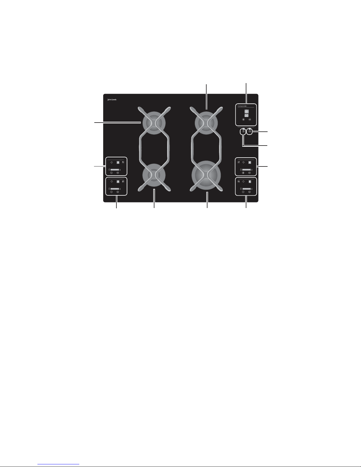
1. Semi-rapid burner
2. Semi-rapid burner
3.
Rear left burner control zone
4. Front left burner control zone
5.
Auxiliary burner
6. Rapid burner
7.
Front right burner control zone
8. Rear right burner control zone
9. Main ON/OFF switch
10. Child safety control
11. Timer control zone
11
2
3
4
5
6
7
8
9
10
1
Your new gas hob offers several innovative functions that
distinguish it from conventional gas hobs.
!
Electronic controlElectronic control
Electronic controlElectronic control
Electronic control
of all functions.
!
TT
TT
T
ouch controuch contr
ouch controuch contr
ouch contr
olsols
olsols
ols
to activate the hob functions simply
by touching them with a finger.
!
ElectrElectr
ElectrElectr
Electr
onic onic
onic onic
onic
TimerTimer
TimerTimer
Timer
to programme your cooking.
!
Automatic reignitionAutomatic reignition
Automatic reignitionAutomatic reignition
Automatic reignition
of the burners if the flame is
accidentally extinguished.
!
Residual heat indicatorResidual heat indicator
Residual heat indicatorResidual heat indicator
Residual heat indicator
to advise that the pan
supports and the burners are still hot.
!
Children safety deviceChildren safety device
Children safety deviceChildren safety device
Children safety device
to prevent the controls from
being accidentally operated.
!
General shutdoGeneral shutdo
General shutdoGeneral shutdo
General shutdo
wnwn
wnwn
wn
to turn off all the burners at once
for an emergency.
!
Safety deviceSafety device
Safety deviceSafety device
Safety device
in case of power failure or burner ignition
failure.
Page 5
5
TT
TT
T
echnical Specificationsechnical Specifications
echnical Specificationsechnical Specifications
echnical Specifications
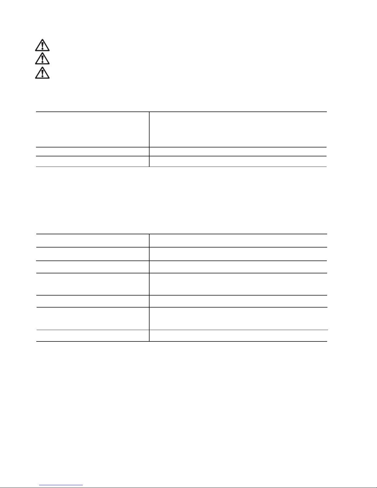
Gas burner powerGas burner power
Gas burner powerGas burner power
Gas burner power
Rapid burner (large) 2.9 kW (Natural gas 20 mbar)
2.7 (LPG 28-30/37 mbar)
Semirapid burner (medium) 1.9 kW
Auxiliary burner (small) 1.0 kW
Supply connectionsSupply connections
Supply connectionsSupply connections
Supply connections
Gas:Gas:
Gas:Gas:
Gas:
R 1/2 inch (1/2 inch male)
Electric:Electric:
Electric:Electric:
Electric:
230 V 50 Hz supply
Appliance classAppliance class
Appliance classAppliance class
Appliance class 3
Appliance categAppliance categ
Appliance categAppliance categ
Appliance categ
oror
oror
or
yy
yy
y
II2H3+II2H3+
II2H3+II2H3+
II2H3+
Appliance gas supplyAppliance gas supply
Appliance gas supplyAppliance gas supply
Appliance gas supply Natural gas G20 / 20 mbar
Overall dimensionsOverall dimensions
Overall dimensionsOverall dimensions
Overall dimensions
Width 730 mm
Depth 510 mm
Cut out dimensionsCut out dimensions
Cut out dimensionsCut out dimensions
Cut out dimensions
Width 710 mm
Depth 470 mm
InstallationInstallation
InstallationInstallation
Installation
It is dangerous to alter the specifications or attempt to modify this product in any way.
Care must be taken to ensure that the appliance does not stand on the electrical supply cable.
Any electrical work required to install this appliance should be carried out by a qualified electrician or competent
person.
Page 6
6
Electrical ConnectionElectrical Connection
Electrical ConnectionElectrical Connection
Electrical Connection
THIS HOB MUST BE EARTHIS HOB MUST BE EAR
THIS HOB MUST BE EARTHIS HOB MUST BE EAR
THIS HOB MUST BE EAR
THEDTHED
THEDTHED
THED
..
..
.
Any electrical work required to install this hob should
be carried out by a qualified electrician or competent
person, in accordance with the current regulations.
Electrical requirementsElectrical requirements
Electrical requirementsElectrical requirements
Electrical requirements
Any permanent electrical installation must comply with the
latest I.E.E. Regulations and local Electricity Board regulations.
For your own safety this should be undertaken by a qualified
electrician, e.g. your local Electricity Board, or a contractor
who is on the roll of the National Inspection Council for
Electrical Installation Contracting (NICEIC).
Electrical connectionsElectrical connections
Electrical connectionsElectrical connections
Electrical connections
This hob is designed to be connected to a 230 V 50 Hz AC
electrical supply.
Before switching on, make sure the electricity supply voltage is
the same as that indicated on the hob rating plate. The rating
plate is located on the bottom of the hob. A copy is attached
on the back cover of this book.
The hob is supplied with a 3 core flexible supply cable.
This has to be provided with a proper plug, able to support
the load marked on the identification plate. The plug has to
be fitted in a proper socket.
In the event of having to change the fuse, a 3amp ASTA
approved (BS 1362) fuse must be used.
"
Should the plug need to be replaced for any reason, the wires
in the mains lead are coloured in accordance with the
following code:
Green and Yellow - Earth
Blue - Neutral
Brown - Live
— Connect the green and yellow (earth) wire to the
terminal in the plug which is marked with the letter
'E' or the earth symbol
or coloured green and
yellow.
— Connect the blue (neutral) wire to the terminal in
the plug which is marked with the letter 'N' or
coloured black.
— Connect the brown (live) wire to the terminal in
the plug which is marked with the letter 'L' or
coloured red.
Upon completion there must be no cut, or stray strands of
wire present and the cable clamp must be secure over the
outer sheath.
A cut off plug inserted into a 13 amp socket is a serious
safety (shock) hazard. Ensure that the cut off plug is
disposed of safely.
Earth (yellow/green)Earth (yellow/green)
Earth (yellow/green)Earth (yellow/green)
Earth (yellow/green)
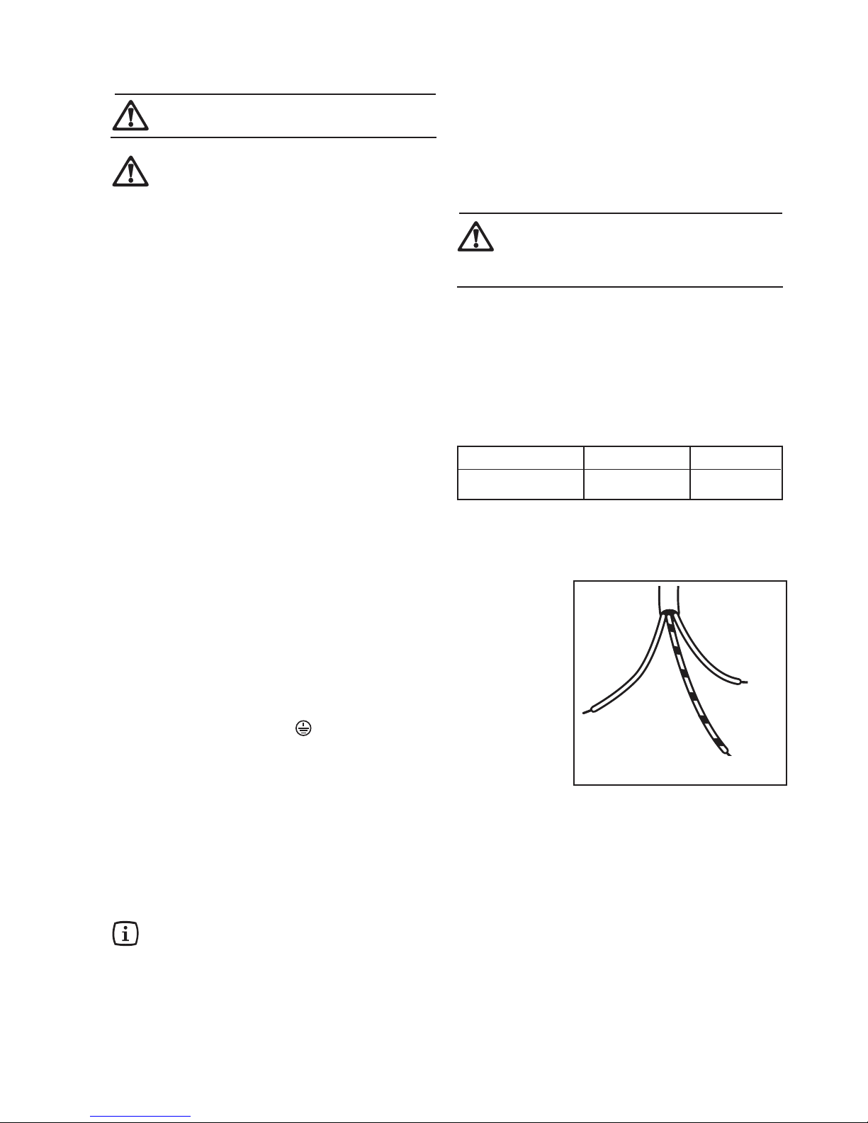
Supply cable replacementSupply cable replacement
Supply cable replacementSupply cable replacement
Supply cable replacement
The cable used to connect the hob to the electrical supply
must comply to the specifications given below.
Min. size Cable/flexMin. size Cable/flex
Min. size Cable/flexMin. size Cable/flex
Min. size Cable/flex
Cable / flex typeCable / flex type
Cable / flex typeCable / flex type
Cable / flex type
FuseFuse
FuseFuse
Fuse
0.75 mm
2
H05 V2V2-F (T90) 3 A
The manufacturer declines any liability should theseThe manufacturer declines any liability should these
The manufacturer declines any liability should theseThe manufacturer declines any liability should these
The manufacturer declines any liability should these
safety measures not be observed.safety measures not be observed.
safety measures not be observed.safety measures not be observed.
safety measures not be observed.
PP
PP
P
ermanent connectionermanent connection
ermanent connectionermanent connection
ermanent connection
In the case of a permanent connection, it is necessary that
you install a double pole switch between the hob and the
electricity supply (mains), with a minimum gap of 3 mm
between the switch contacts and of a type suitable for the
required load in compliance with the current electric
regulations.
The switch must not break the yellow and greenThe switch must not break the yellow and green
The switch must not break the yellow and greenThe switch must not break the yellow and green
The switch must not break the yellow and green
earth cable at any point. It is necessary thatearth cable at any point. It is necessary that
earth cable at any point. It is necessary thatearth cable at any point. It is necessary that
earth cable at any point. It is necessary that
the yellow / green earthwire is about 2 cmthe yellow / green earthwire is about 2 cm
the yellow / green earthwire is about 2 cmthe yellow / green earthwire is about 2 cm
the yellow / green earthwire is about 2 cm
longer than the live and neutral ones.longer than the live and neutral ones.
longer than the live and neutral ones.longer than the live and neutral ones.
longer than the live and neutral ones.
Ensure that the hob supply cable does not come into contact
with surfaces with temperatures higher than 50 deg. C.
NeutralNeutral
NeutralNeutral
Neutral
Page 7
7
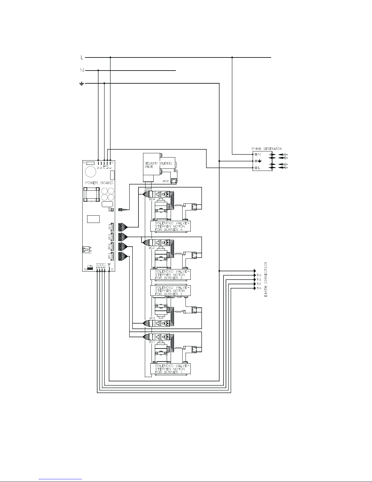
Wiring DiagramWiring Diagram
Wiring DiagramWiring Diagram
Wiring Diagram
Page 8
8
ImporImpor
ImporImpor
Impor
tant Saftant Saf
tant Saftant Saf
tant Saf
ety Requirety Requir
ety Requirety Requir
ety Requir
ementsements
ementsements
ements
This hob must be installed in accordance with the Gas Safety
(Installation and Use) Regulations (Current Edition) and the
IEE Wiring Regulations (Current Edition).
For appliances installed in the Republic of Ireland please refer
to NSAI- Domestic Gas Installation I.S. 813 Current Editions
and the ETCI Rules for Electrical Installations.
PrPr
PrPr
Pr
oo
oo
o
vision fvision f
vision fvision f
vision f
or vor v
or vor v
or v
entilationentilation
entilationentilation
entilation
Detailed recommendations are contained in the following British
Standards Codes Of Practice: B.S. 6172/ B.S. 5440, Part 2 and
B.S. 6891 Current Editions.
The hob should not be installed in a bed sitting room with a
volume of less than 20 m
3
. If it is installed in a room of volume
less than 5 m
3
an air vent of effective area of 110 cm2 is required.
If it is installed in a room of volume between 5 m
3
and 10 m
3
an air vent of effective area of 50 cm2 is required, while if the
volume exceeds 11 m
3
no air vent is required. However, if the
room has a door which opens directly to the outside no air
vent is required even if the volume is between 5 m
3
and 11 m3.
If there are other fuel burning appliances in the same room,
B.S. 5440 Part 2 Current Edition, should be consulted to
determine the requisite air vent requirements.
For appliances installed in the Republic of Ireland please refer
to the NSAI- Domestic Gas Installation I.S. 813 Current
Editions Table Four.
LocationLocation
LocationLocation
Location
The hob may be located in a kitchen, a kitchen/diner or bed
sitting room, but not in a bathroom or shower room.
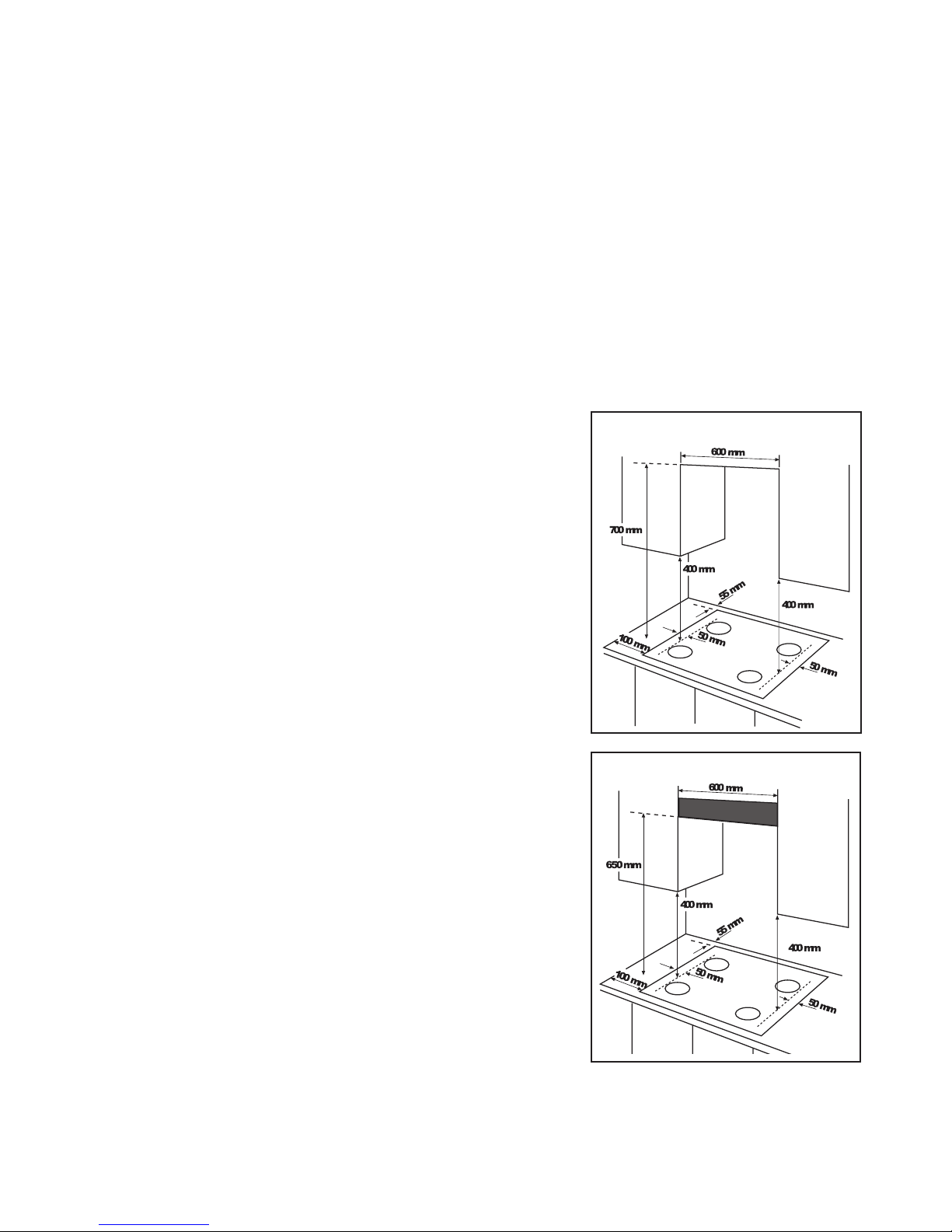
Before making the cut out in the worktop ensure that the
edges of the hob that are to be near either a side or rear wall
have a minimum distance of 55 mm. between the edge of the
hob and the wall.
The minimum distance combustible material can be fitted above
the hob is 400 mm. If it is fitted below 400 mm. a space of 50
mm. must be allowed from the edges of the hob. The minimum
distance combustible material can be fitted directly above the
hob is 700 mm.
A minimum distance of 100 mm. must be left between the
side edges of the hob and any adjacent cabinets or walls.
For appliances installed in the Republic of Ireland please refer
to NSAI- Domestic Gas Installation I.S 813 Current Edition
Section 7- Permitted Locations of Appliance.
FITTING THE GAS HOBFITTING THE GAS HOB
FITTING THE GAS HOBFITTING THE GAS HOB
FITTING THE GAS HOB
WITHOUT A COOKER HOOD ABOVEWITHOUT A COOKER HOOD ABOVE
WITHOUT A COOKER HOOD ABOVEWITHOUT A COOKER HOOD ABOVE
WITHOUT A COOKER HOOD ABOVE
FITTING THE GAS HOBFITTING THE GAS HOB
FITTING THE GAS HOBFITTING THE GAS HOB
FITTING THE GAS HOB
WITH A COOKER HOOD ABOVEWITH A COOKER HOOD ABOVE
WITH A COOKER HOOD ABOVEWITH A COOKER HOOD ABOVE
WITH A COOKER HOOD ABOVE
Page 9
9
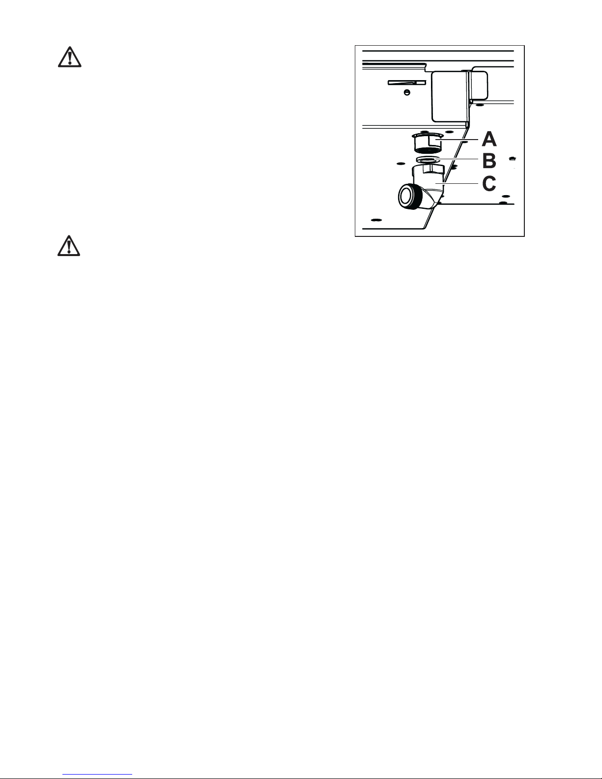
ConnectionConnection
ConnectionConnection
Connection
IMPORTANT: IMPORTANT:
IMPORTANT: IMPORTANT:
IMPORTANT: This hob must be installed by a
competent person to the relevant Gas Standards.
Any gas installation must be carried out by a competent
person.
The manufacturer will not accept liability, should the
above instructions or any of the other safety instructions
incorporated in this book be ignored.
Carry out connection to the gas supply using a rigid metal
pipe with connections conforming to the rules in force, or
with a flexible s/steel tube conforming to the relevant rules in
force, limited to those whose max. length is 2 m. If flexible
metal tubes are used, make sure they do not come into contact
with mobile parts or are crushed. Pay the same attention also
when an oven and top combination is provided for. The
appliance gas inlet connection is 1/2" cylindrical threaded
male.
Screw the parts together without using excessive force.
IMPORIMPOR
IMPORIMPOR
IMPOR
TT
TT
T
ANTANT
ANTANT
ANT
::
::
:
After installation,After installation,
After installation,After installation,
After installation,
al al
al al
al
wawa
wawa
wa
ys checkys check
ys checkys check
ys check
the perfect tightness of all the connections,the perfect tightness of all the connections,
the perfect tightness of all the connections,the perfect tightness of all the connections,
the perfect tightness of all the connections,
using a soapy solution. NEVER carry out thisusing a soapy solution. NEVER carry out this
using a soapy solution. NEVER carry out thisusing a soapy solution. NEVER carry out this
using a soapy solution. NEVER carry out this
check with a flame.check with a flame.
check with a flame.check with a flame.
check with a flame.
AA
AA
A) Gas ramp end with nut
BB
BB
B) Washer
CC
CC
C) Elbow
Page 10

10
Replacing the injectorsReplacing the injectors
Replacing the injectorsReplacing the injectors
Replacing the injectors
1. Remove the pan supports.
2. Remove the burner caps and crowns.
3. Using a 7 mm socket spanner
unscrew and remove the
injectors
, then replace them with the ones required for
the new type of gas
(see the table “Burner characteristics”).
4.
Reassemble the parts, following the same procedure
backwards.
5. Replace the Gas Type Label (located near the gas supply
connection) with the one corresponding to the new type
of gas. The label is supplied in the accessories plastic bag.
Should the feeding gas pressure be different or variable
compared with the required pressure, an appropriate pressure
regulator must be fitted on the gas supply pipe, in compliance
with the rules in force.
GAS BURNER INJECTOR NOMINAL REDUCED NOMINAL FEEDING
TYPE TYPE REFERENCE THERMAL THERMAL FLOW RATE PRESSURE
1/100 mm POWER POWER
kW kW m3/h g/h mbar
Rapid 119 2.9 0.65 0.276
Semirapid 96 1.9 0.45 0.181 - 20
Auxiliary 70 1.0 0.33 0.095 -
Rapid 86 2.7 0.65 - 196
Semirapid 71 1.9 0.45 - 138 28-30/37
Auxiliary 50 1.0 0.33 - 73
Burner characteristicsBurner characteristics
Burner characteristicsBurner characteristics
Burner characteristics
ConCon
ConCon
Con
vv
vv
v
ersion frersion fr
ersion frersion fr
ersion fr
om Natural Gas to LPGom Natural Gas to LPG
om Natural Gas to LPGom Natural Gas to LPG
om Natural Gas to LPG
NATURAL
GAS (G20)
LIQUID
GAS
(Butane/
Propane)
Page 11

11
5. Touch the Decreasing Control
to select the required
type of gas.
6. After selecting the type of gas, switch off the hob touching
the main ON/OFF Control
.
7. Touch the main ON/OFF Control
again to reactivate
the hob.
The appliance is automatically set to the normal “User
Mode”.
8. Light all the burners and adjust their flame to minimum,
in order to check the flame stability (visual check).
9. At the same time, check the flame aspect (visual check).
If both the flame stability and the flame aspect are satisfactory,
the setting of the hob for the new gas type is completed.
If the flame stability is not satisfactory, carry out an additional
adjustment as described in the following paragraph.
Setting the hob for the new gas typeSetting the hob for the new gas type
Setting the hob for the new gas typeSetting the hob for the new gas type
Setting the hob for the new gas type
1. If necessary, activate the hob by touching the main ON/
OFF Control
for about 3 seconds.
2. Touch the Timer Control
repeatedly to select the
auxiliary burner (front left burner) on the burner selection
display .
3. Touch the Increasing Control
and hold the finger on
it until the value 99 appears on the time display. Then,
touch the Decrasing Control
and hold the finger on
it until the value 80 is displayed.
4. Then, touch the Increasing Control
until 83 is
displayed. At this point, the hob is set to the “
Gas ChangeGas Change
Gas ChangeGas Change
Gas Change”
mode and the current gas setting appears on the display:
-
n0n0
n0n0
n0 stands for gas G20 (20 mbar)
-
n1n1
n1n1
n1
for gas G30 (28-30/37 mbar).
IMPORTANT: setting
n2 n2
n2 n2
n2 does not allow the hob to
function.
Page 12

12
Minimum flame adjustmentMinimum flame adjustment
Minimum flame adjustmentMinimum flame adjustment
Minimum flame adjustment
If it is necessary to adjust the minimum flame setting, proceed
as follows:
1. Carry out the steps described in the paragraph “Setting
the hob for the new gas type” - points 1, 2, 3, 4 and 5.
2. Light the burner to be adjusted by touching the Burner
Ignition Control
.
The burner lights at the maximum flame level and, after a
regular flame is obtained, it sets at the minimum flame
level .
3. If the minimum level is too low or not satisfactory to
maintain the burner lit, touch the Increasing
or
Decreasing
Control to carry out a fine adjustment
(visual check).
4. Switch off the hob touching the main ON/OFF
Control
.
Page 13

13
Building InBuilding In
Building InBuilding In
Building In
The hob is designed to be inserted in modular kitchen units
with depth of 550 - 600 mm and having proper characteristics.
The building-in is also possible in modular units with a 600
mm width: in this case, the cut-out in the work top must be
carried out as shown in Fig. 2.
The worktop must be at least 30 mm thick.
If the worktop is thicker than 50 mm, it is possible to install
the hob on modular units of any width.
Any unit (furniture unit, household appliance, etc..) placed
near the unit which the hob is built in, shall not exceed the
worktop height.
A minimum clearance of 100 mm between theA minimum clearance of 100 mm between the
A minimum clearance of 100 mm between theA minimum clearance of 100 mm between the
A minimum clearance of 100 mm between the
cut-out in the worktop and any side wallcut-out in the worktop and any side wall
cut-out in the worktop and any side wallcut-out in the worktop and any side wall
cut-out in the worktop and any side wall
exceeding the worktop height must beexceeding the worktop height must be
exceeding the worktop height must beexceeding the worktop height must be
exceeding the worktop height must be
observed.observed.
observed.observed.
observed.
The hob dimensions and the cut-out dimensions are given in
fig. 1 and 2.
Fig. 2Fig. 2
Fig. 2Fig. 2
Fig. 2
Dimensions are givenDimensions are given
Dimensions are givenDimensions are given
Dimensions are given
in millimetresin millimetres
in millimetresin millimetres
in millimetres
730730
730730
730
AA
AA
A
SRSR
SRSR
SR
SRSR
SRSR
SR
RR
RR
R
Fig. 1Fig. 1
Fig. 1Fig. 1
Fig. 1
A) Worktop
B) Removable Panel
510510
510510
510
AA
AA
A
==
==
=
Auxiliary burnerAuxiliary burner
Auxiliary burnerAuxiliary burner
Auxiliary burner
SRSR
SRSR
SR
==
==
=
Semirapid burnerSemirapid burner
Semirapid burnerSemirapid burner
Semirapid burner
RR
RR
R
= =
= =
=
Rapid burnerRapid burner
Rapid burnerRapid burner
Rapid burner
Page 14

14
Fitting the hob to the worktopFitting the hob to the worktop
Fitting the hob to the worktopFitting the hob to the worktop
Fitting the hob to the worktop
Before fitting the hob into the cut out, an adhesive seal must
be fitted to the underside outside edge of the hob. It is essential
that no gaps are left in this seal in order to prevent spillage
near the hob seeping into the cabinet below.
Proceed as follows:
1.1.
1.1.
1 . Remove the pan supports, the burner caps and crowns
and turn the hob upside down, taking care that the spark
plugs and the thermocouples are not damaged in this
operation.
2.2.
2.2.
2 . Place the sealing gasket all around the glass top edge as
shown in Fig. 3.
3.3.
3.3.
3 . Fit the hob in the cut out and push it down until the glass
top and the worktop make contact, as shown in Fig. 4.
The side springs ensure centering.
"
A) SealA) Seal
A) SealA) Seal
A) Seal
A
Fig. 3Fig. 3
Fig. 3Fig. 3
Fig. 3
Fig. 4Fig. 4
Fig. 4Fig. 4
Fig. 4
Page 15

15
Fig. 7Fig. 7
Fig. 7Fig. 7
Fig. 7
Fig. 8Fig. 8
Fig. 8Fig. 8
Fig. 8
Fig. 6Fig. 6
Fig. 6Fig. 6
Fig. 6
Hanging furniture units or hoods must be placed at 650 mm.
minimum from the hob (Fig. 6).
The electronic gas hob can only be installed over a
built-in oven equipped with cooling fan.
If the hob is installed over a built-in oven equipped
with pyrolytic cleaning function, the hob must not be
in use while the pyrolytic cleaning cycle of the oven is
running.
a) removable panel
b) space for connections
Fig. 5Fig. 5
Fig. 5Fig. 5
Fig. 5
Building over a kitchen unit with doorBuilding over a kitchen unit with door
Building over a kitchen unit with doorBuilding over a kitchen unit with door
Building over a kitchen unit with door
Proper arrangements must be taken in designing the furniture
unit, in order to avoid any contact with the bottom of the
hob which can be heated when it is operated. The
recommended solution is shown in Fig. 5.
The panel fitted under the hob ("a") should be easily
removable to allow easy access if technical assistance is needed.
See also Fig. 2.
The space behind the kitchen unit ("b") can be used for
connections.
Dimensions are in mmDimensions are in mm
Dimensions are in mmDimensions are in mm
Dimensions are in mm
Building over a unit with an ovenBuilding over a unit with an oven
Building over a unit with an ovenBuilding over a unit with an oven
Building over a unit with an oven
The recesses for the hob and the oven must comply the
indication given in Figs. 6 and must be provided with openings
to allow a continuous supply of air.
Two possible solutions to avoid excessive overheating are
described in Fig. 7 and 8.
The electrical connection for the hob and the oven must be
carried out separately, for safety reasons and also to allow
the oven to be easily removed from the unit, if necessary.
Installation PInstallation P
Installation PInstallation P
Installation P
ossibilitiesossibilities
ossibilitiesossibilities
ossibilities
Page 16

16
The ContrThe Contr
The ContrThe Contr
The Contr
ol Panelol Panel
ol Panelol Panel
ol Panel
Before using the appliance, remove all packaging,
including the advertising labels and any protective
film.
Keep packaging away from children.
TT
TT
T
ouch controuch contr
ouch controuch contr
ouch contr
olsols
olsols
ols
The hob is supplied with special Touch Controls. To operate
your hob, simply touch the required control with a fingertip.
Ensure to only touch one control at a time during use.
Here follow the symbols for the main Touch Controls, and
the relevant indicators
Main ON/OFF Touch Control
Burner Ignition Touch Control
Flame level indicators
Increasing Touch Control for the flame
level
Decreasing Touch Control for the flame level
Residual heat indicator
BurnerBurner
BurnerBurner
Burner
control zonecontrol zone
control zonecontrol zone
control zone
Page 17

17
How to light a burnerHow to light a burner
How to light a burnerHow to light a burner
How to light a burner
1. Touch the main ON/OFF Control for about 3 seconds
to switch on the hob. The red indicator above the touch
control lights up, an acoustic signal sounds and the hob is
ready to use.
2. Touch the Burner Ignition Touch Control
of the
required burner. The flame level indicators located right
above the symbols
and illuminate.
3. Within about 3 seconds, touch the Increasing
or
Decreasing
Touch Control to light the burner.
- If touch control
is selected, the burner automatically
lights at maximum flame level (all the flame level indicators
illuminate).
- If touch control
is selected, the burner automatically
lights at medium flame level (three flame level indicators
illuminate).
4. To adjust the burner flame level, use the Increasing
or
Decreasin
g Touch Control.
The residual heat indicator lights up immediately after
the burner is lit.
This means that the cooking zone is getting hot: the
indicator remains on until the pan support and the burner
have cooled down.
"
Page 18

18
In case of accidental extinguishingIn case of accidental extinguishing
In case of accidental extinguishingIn case of accidental extinguishing
In case of accidental extinguishing
(automatic re(automatic re
(automatic re(automatic re
(automatic re
ignitionignition
ignitionignition
ignition
))
))
)
If the burner flame is accidentally extinguished (draughts, spilling of
liquids, etc.), the gas flow is immediately interrupted.
After about 20 seconds,
the ignition device automatically repeats
the ignition procedure
.
Upon reignition, the burner flame is first set at maximum
level, then it is automatically adjusted to the level set before it
was accidentally extinguished.
If three consecutive reignition attempts fail, a safety device is
set on the burner. The flame level indicators and the residual
heat indicator flash.
Caution! When the safety device is set on a burner,
the burner controls cannot be operated for about 60
seconds.
After 60 seconds, you can remove the safety device on the
burner by touching both
the Increasing Controls and the
Decreasing Control
at the same time.
Then, follow the instructions given in the paragraph “How to
light a burner”.
"
Caution! Check that the burner cap is correctly
positioned (see diagram).
If the ignition problem persists, refer to chapter
“Something not working”.
Never use a manual spark gas-lighter if the burner
ignition device does not work correctly. If necessary,
use a match.
Burner
Cap
Spark
plug
Thermocouple
How to turn off a burnerHow to turn off a burner
How to turn off a burnerHow to turn off a burner
How to turn off a burner
1. To turn off a burner press the relevant Burner Ignition
Touch Control
. All the flame level indicators go off.
The residual heat indicator remains on until the pan
support and the burner have cooled down.
In case of ignition failureIn case of ignition failure
In case of ignition failureIn case of ignition failure
In case of ignition failure
The hob ignition device generates a series of small sparks for
about 6 seconds.
If the flame does not light during this period, the gas flow to
the burner is interrupted. After 3 seconds, the ignition device
automatically repeats the ignition procedure for another 6
seconds.
After three failed ignition attempts, a safety device is set on
the burner. The flame level indicators flash.
Caution! When the safety device is set on a burner,
the burner controls cannot be operated for about 60
seconds.
After 60 seconds, you can remove the safety device on the
burner by touching both the Increasing Controls
and
the Decreasing Control
at the same time.
Then, follow the instructions given in the paragraph “How to
light a burner”.
"
"
Page 19

19
HoHo
HoHo
Ho
w to turn off all the burnersw to turn off all the burners
w to turn off all the burnersw to turn off all the burners
w to turn off all the burners
at onceat once
at onceat once
at once
In case of unexpected safety hazard (spilling of liquids,
children hazard, etc.)
, you can immediately turn off all the
hob burners at once by touching
the main ON/OFF Control
.
"
Burner safety cut-off functionBurner safety cut-off function
Burner safety cut-off functionBurner safety cut-off function
Burner safety cut-off function
If you leave one or more burners lit and unattended for a
long time (that is, you do not touch any control for at least 4
hours), each lit burner is automatically turned off and a safet
y
device is set on it.
If you select the burner that does not work with the
Timer Control
Code number 10 Code number 10
Code number 10 Code number 10
Code number 10 flashes in the
cooking time display.
Caution! When the safety device is set on a burner,
the burner controls cannot be operated for about 60
seconds.
After 60 seconds, you can remove the safety device on the
burner by touching both the Increasing Controls
and
the Decreasing Control
at the same time.
Then, follow the instructions given in the paragraph “How to
light a burner”.
Hob safety cut-off functionHob safety cut-off function
Hob safety cut-off functionHob safety cut-off function
Hob safety cut-off function
If no burner is on but the hob is activated (the red indicator
above the touch control
is on), the hob is automatically
switched off if no control is operated within 30 minutes.
"
"
Protection against overheatingProtection against overheating
Protection against overheatingProtection against overheating
Protection against overheating
If the hob is used intensively, e.g. several burners at maximum
level for a long time, a temperature sensor detects possible
overheating and automatically adjusts all the lit burners to
minimum.
If the
hob temperature keeps rising although the flame level
has been reduced, all the lit burners are automatically turned
off and a safety device is set on all the four burners.
If you select all the burners with the Timer Control
(one at a time)
Code number 9 Code number 9
Code number 9 Code number 9
Code number 9 flashes in the
cooking time display.
Caution! When the safety device is set on all the
burners, their controls cannot be operated for about
60 seconds.
After the 60 seconds, you can reactivate all the burners by
touching the Increasing Control
and the Decreasing Control
of one of the four burners at the same time.
Once the safety device has been removed, wait until the hob
has cooled down before using it again.
"
Page 20

20
The electronic timerThe electronic timer
The electronic timerThe electronic timer
The electronic timer
Your hob is supplied with an electronic timer enabling you to
programme the cooking duration. The timer can also be used
as a minute minder, when the hob is not in use.
The hob can even be used manually, i.e. without any
programming.
The timer only operates when the hob is switched
on by means of the main ON/OFF Control
.
Here follow the symbols in the Timer Control Zone:
Touch Control to activate the Timer and select a burner.
Cooking time display
Burner selection display
Increasing Touch Control for the time
setting.
Decreasing Touch Control for the
time setting.
TimerTimer
TimerTimer
Timer
control zonecontrol zone
control zonecontrol zone
control zone
"
Child safety functionChild safety function
Child safety functionChild safety function
Child safety function
To avoid children operating the hob controls, it is possible to
lock them.
1. Touch the “Key” Control
for about 3 seconds. The
red indicator above the “
Key” symbol lights up and
an acoustic signal sounds.
Now all the hob controls are locked, except the main ON/
OFF Touch Control.
Any lit burner keeps operating, but cannot be adjusted.
2. To unlock the hob controls, touch the “Key” Control
for about 3 seconds. The red indicator above the “Key”
symbol
goes off and an acoustic signal sounds.
It is highly recommended to activate the child safety
function every time the hob is not operated.
In case of a power failure, the hob stores the children
safety function setting in the system memory. If the
controls are locked at the time of the power failure,
they will still be locked when the power is restored.
Page 21

21
How to programme a burner toHow to programme a burner to
How to programme a burner toHow to programme a burner to
How to programme a burner to
switch offswitch off
switch offswitch off
switch off
To programme a burner to switch off, proceed as follows:
1. If necessary, activate the hob by
touching the main ON/
OFF Control
for about 3 seconds.
2. Light the burner and adjust the flame level using the
Increasing
or Decreasing controls (see par. “How
to light a burner”).
3. Activate the Timer by touching the Timer Control
and select the required burner by repeatedly touching
the Timer Control
.
4. Set the required cooking time touching the Increasing
and Decreasing Controls.
(max. time: 99 minutes).
Once the cooking time has been set, the burner
selection can no longer be changed.
If you want to change burner, you must set the cooking
time to zero by means of the Decreasing
control,
and then change the burner selection by touching
the Timer Control
.
5. The timerstarts the countdown a few seconds after the
cooking time has been set.
6. During the last ten seconds, the timer starts beeping to
advise that the cooking time is about to end.
7. An acoustic signal sounds at the end of the cooking time.
To stop the acoustic signal, touch the Timer
Control .
TT
TT
T
o adjust the cooking time:o adjust the cooking time:
o adjust the cooking time:o adjust the cooking time:
o adjust the cooking time:
1. Touch the Increasing
or Decreasing Control or
at any time to adjust the time setting.
TT
TT
T
o cancel the time setting:o cancel the time setting:
o cancel the time setting:o cancel the time setting:
o cancel the time setting:
1. Touch the Decreasing
Control to set the cooking
time to zero.
It is
possible to programme the switch-off of
ONLONL
ONLONL
ONL
YY
YY
Y
one burner at a time.
You can set the cooking time as well when the burner
is already lit.
For example, you can bring a pot of water to the boil,
then put some vegetables, meat or pasta and
programme the required time for their cooking.
The residual heat indicators remain on even when
the hob is off, until the burner and the pan supports
have cooled down.
"
Page 22

22
HoHo
HoHo
Ho
w to w to
w to w to
w to
set the minset the min
set the minset the min
set the min
ute minderute minder
ute minderute minder
ute minder
ff
ff
f
unctionunction
unctionunction
unction
You can use the timer as a simple minute minder when none
of the burners are operating.
The hob must be activated in order to use the timer as a
minute minder.
Proceed as follows:
1. If necessary, activate the hob by touching the main ON/
OFF Control
for about 3 seconds.
2. Touch the Timer Control to activate the timer.
3. Touch the Increasing or Decreasing controls to
set the required time (max. time: 99 minutes).
4. The timer begins the countdown a few seconds after the
time has been set.
5. During the last ten seconds, the timer starts beeping to
advise that the timed period is about to end.
6. An acoustic signal sounds at the end of the timed period.
To stop the acoustic signal, touch the Timer
Control .
TT
TT
T
o adjust the time setting:o adjust the time setting:
o adjust the time setting:o adjust the time setting:
o adjust the time setting:
1. Touch the Increasing
or Decreasing Control or at
any time to adjust the minute minder setting.
TT
TT
T
o cancel the time setting:o cancel the time setting:
o cancel the time setting:o cancel the time setting:
o cancel the time setting:
1. Touch the Decreasing
Control to set the minute
minder to zero.
"
Page 23

23
SafSaf
SafSaf
Saf
ety and energety and energ
ety and energety and energ
ety and energ
y-say-sa
y-say-sa
y-sa
ving adviceving advice
ving adviceving advice
ving advice
FF
FF
F
or a coror a cor
or a coror a cor
or a cor
rr
rr
r
ect use of the hobect use of the hob
ect use of the hobect use of the hob
ect use of the hob
To ensure maximum burner efficiency and lower gas
consumption
, you should only use pots and pans with a flat
bottom fitting the size of the burner used (see table).
If you use a saucepan which is smaller than the
recommended size, the flame will spread beyond the
bottom of the vessel, causing the handle to overheat.
Pots must never be placed onto the control zones.
Always turn the flame down or off before removing
pots from the burners.
Take care when frying food in hot oil or fat, as the
overheated splashes could easily ignite.
For an easier ignition of the burner, light it before
placing the pan on the pan support.
Unstable or misshapen pans should not be used on
the hob as unstable pans can cause an accident by
tipping or spillage.
It is advisable to cook with lids on.
By using a pressure cooker you will obtain further
energy-saving and shorter cooking times.
As soon as a liquid starts boiling, turn down the flame
so that it will barely keep the liquid simmering.
Avoid cooking with potstones, earthenware pots or
cast iron plates. Also, avoid using aluminiun foil for
protecting the top during operation.
BurnerBurner
BurnerBurner
Burner
diameterdiameter
diameterdiameter
diameter
diameterdiameter
diameterdiameter
diameter
min.min.
min.min.
min.
max.max.
max.max.
max.
Large (rapid) 160 mm 240 mm
Medium (semirapid) 120 mm 220 mm
Small (Auxiliary) 80 mm 160 mm
Page 24

24
Cooking tableCooking table
Cooking tableCooking table
Cooking table
Where two burners are indicated in the table, it is recommended that you choose the burner taking into consideration
the quantity of food to be cooked.
DISHESDISHES
DISHESDISHES
DISHES
SoupsSoups
SoupsSoups
Soups Broths 15-20 minutes x
FishFish
FishFish
Fish Court- bouillon x
Hollandaise x
SaucesSauces
SaucesSauces
Sauces
Bechamel 10 minutes x
Endives x
VV
VV
V
egetablesegetables
egetablesegetables
egetables
Peas in sauce 25-30 minutes x x
Provence tomatoes 15-20 minutes x x
Fried potatoes x x
Pasta x
MeatMeat
MeatMeat
Meat Steak (in pot) x
Fried escalope 10-12 minutes x
FryingFrying
FryingFrying
Frying Chips 18-22 minutes x
Rice pudding 35 minutes x
Stewed fruit x x
DessertsDesserts
DessertsDesserts
Desserts Pancakes 3-4 minutes x
Chocolate 5-6 minutes x
Custard 20-25 minutes x
RecommendedRecommended
RecommendedRecommended
Recommended
cooking timecooking time
cooking timecooking time
cooking time
(Where no
recommendation
is given, times
should be set
according
to your personal
requirements)
RAPIDRAPID
RAPIDRAPID
RAPID
AA
AA
A
UXILIARUXILIAR
UXILIARUXILIAR
UXILIAR
YY
YY
Y
SEMI-RAPIDSEMI-RAPID
SEMI-RAPIDSEMI-RAPID
SEMI-RAPID
BURNER POBURNER PO
BURNER POBURNER PO
BURNER PO
WERWER
WERWER
WER
Page 25

25
Before any maintenance or cleaning can be carried
out, you must DISCONNECT the hob from the
electricity supply and wait until it has cooled down.
This appliance cannot be cleaned with steam or with a
steam cleaning machine.
The hob topThe hob top
The hob topThe hob top
The hob top
Regularly wipe over the hob top using a soft cloth well wrung
out in warm water to which a little washing up liquid has
been added. Avoid the use of the following:
- household detergent and bleaches;
- impregnated pads unsuitable for non-stick saucepans;
- steel wool pads;
- bath/sink stain removers.
Should the hob top become heavily soiled, it is recommended
that proper cleaning product is used.
If scratches or cracks are noticed on the glass top,
immediately disconnect the appliance from the
electrical supply to avoid the risk of electrical shock.
Then, contact your local Service Force Centre and
avoid using the appliance until it has been repaired.
Pan supportsPan supports
Pan supportsPan supports
Pan supports
The pan supports are dishwasher proof. If washing them by
hand, take care when drying them as the enamelling process
occasionally leaves rough edges. If necessary, remove stubborn
stains using a paste cleaner.
Pay attention when replacing the pan supports in order
to avoid scratching the glass hob top.
The burnersThe burners
The burnersThe burners
The burners
The cap and the crown of each burner are secured with two
screws. To separate the two pieces, lift the cap, turn it upside
down, then undo the two fixing screws as shown in the
diagram.
After a thoroughly cleaning, reassemble the two parts and refit
the cap in its correct position on the burner.
Frequently wash the burner caps and crowns using hot soapy
water and remove marks with a mild paste cleaner. A well
moistened soap impregnated steel wool pad can be used with
caution, if the marks are particularly difficult to remove.
For stubborn stains, use normal non-abrasive cleaners or
specific products available on the market. NEVER use scouring
pads, steel wool or acids for cleaning.
TT
TT
T
he he
he he
he
ignition systemignition system
ignition systemignition system
ignition system
The electric ignition is obtained through a spark plug and a
metal electrode (letter A).
Keep these components clean, to avoid difficult lighting, and
check that the burner crown holes are not obstructed.
Maintenance and CleaningMaintenance and Cleaning
Maintenance and CleaningMaintenance and Cleaning
Maintenance and Cleaning
AA
AA
A-
Spark plug
BB
BB
B - Thermocouple
BB
BB
B
AA
AA
A
Page 26

26
Something Not Something Not
Something Not Something Not
Something Not
WW
WW
W
orkingorking
orkingorking
orking
SS
SS
S
olutionsolutions
olutionsolutions
olutions
Have the fuses replaced.
Reset the switches.
Touch the main On/Off Control
.
Open the tap.
Purchase a new bottle.
Allow the top to cool (see par.
“Protection against overheating”).
Deactivate the Child Safety function
(see par. “Child Safety Function”).
Wait 60 seconds, then follow the
instructions given in chapter: “In case
of ignition failure”.
Check the correct position (see par. “In
case of ignition failure”)
.
Follow the instructions given in the
section “Cleaning and maintenance”.
Contact an authorized technical
assistance centre
.
See paragraph “How to light a burner”.
SymptonSympton
SymptonSympton
Sympton
THE HOB
DOES NOT WORK.
A BURNER
DOES NOT WORK.
IT TAKES TOO LONG
TO FINISH THE DISHES / THEY ARE
COOKED TOO FAST.
PP
PP
P
ossible causeossible cause
ossible causeossible cause
ossible cause
There are blown fuses in the domestic
electrical system. Switches are turned off
or there is no power at the power outlet.
The hob is not activated.
The main gas supply tap is closed.
The gas bottle is empty.
The hob has overheated and a safety device
has been set on the four burners.
The Child Safety function has been
inadvertently activated.
The safety device has been set on the
burner due to repeated ignition failures.
The flame level indicators and the residual
heat indicator flash.
The pan support or the burner cap and
crown were not correctly positioned after
cleaning.
The burner crown holes are obstructed.
The defect persists.
The flame level adjustment is not
appropriate.
If the hob is not working correctly, please carry out the following checks, before contacting your local Service Force repair
agent.
In the event of any other fault codes that arise, disconnect the appliance from the electrical supply for a few seconds (take
outthe fuse from the housing wiring system). If the fault code is displayed again, please call your local Service Force repair
agent and report the fault code.
IMPORIMPOR
IMPORIMPOR
IMPOR
TT
TT
T
ANTANT
ANTANT
ANT
::
::
: If you call out an engineer to a fault listed below, or to repair a fault caused by incorrect use or installation,
acharge will be made even if the appliance is under guarantee.
Page 27

27
Repairs - Repairs -
Repairs - Repairs -
Repairs -
After Sales SerAfter Sales Ser
After Sales SerAfter Sales Ser
After Sales Ser
vicevice
vicevice
vice
If your hob is not performing satisfactorily; consult the fault
finding guide within this instruction manual (“Something Not
Working” on the previous page). If a fault occurs which you
can not resolve through following the advice and information
contained within this instruction manual, the next step is to
contact our extended warranty administrators on
0870 01078870870 0107887
0870 01078870870 0107887
0870 0107887
They will give you details for your local Service Force Centre.
Before calling out an engineer, please ensure you have read
the details under the heading “Something Not Working”.
When you contact your local Service Force Centre you will
need to give the following details:
1.Your name, address and post code
2.Your telephone number
3.Clear and concise details of fault
4.The purchase date and found on your receipt
5.The model and serial number of the appliance.
These details have been provided separately within the pack
containing this instruction manual.
Mod. : . . . . . . . . . . . . . . . . . .
PNC : . . . . . . . . . . . . . . . . . .
S.N. : . . . . . . . . . . . . . . . . . . .
YY
YY
Y
our hob is coour hob is co
our hob is coour hob is co
our hob is co
vv
vv
v
erer
erer
er
ed bed b
ed bed b
ed b
y a 3 yy a 3 y
y a 3 yy a 3 y
y a 3 y
ear parear par
ear parear par
ear par
ts and labourts and labour
ts and labourts and labour
ts and labour
guarantee (see separate details given at point of sale).guarantee (see separate details given at point of sale).
guarantee (see separate details given at point of sale).guarantee (see separate details given at point of sale).
guarantee (see separate details given at point of sale).
Please retain your purchase receipt safely for thePlease retain your purchase receipt safely for the
Please retain your purchase receipt safely for thePlease retain your purchase receipt safely for the
Please retain your purchase receipt safely for the
service engineer to verify the purchase details.service engineer to verify the purchase details.
service engineer to verify the purchase details.service engineer to verify the purchase details.
service engineer to verify the purchase details.
Spare partsSpare parts
Spare partsSpare parts
Spare parts
This product should be serviced by an authorised service
engineer, and only genuine spare parts should be used.
Under no circumstances should you attempt to repair the hob
yourself.
Repairs carried out by inexperienced persons may cause injury
or serious malfunctioning. Contact our extended warranty
administrators on
0870 01078870870 0107887
0870 01078870870 0107887
0870 0107887
who will give you details for your local repair agent.
Always insist on genuine spare parts.
Page 28

35692-8601 07/06 R.0
Grafiche MDM - Forlì
John Lewis PartnershipJohn Lewis Partnership
John Lewis PartnershipJohn Lewis Partnership
John Lewis Partnership
171 Victoria Street
London SWIE 5NN
www.johnlewis.com
 Loading...