

Page 1
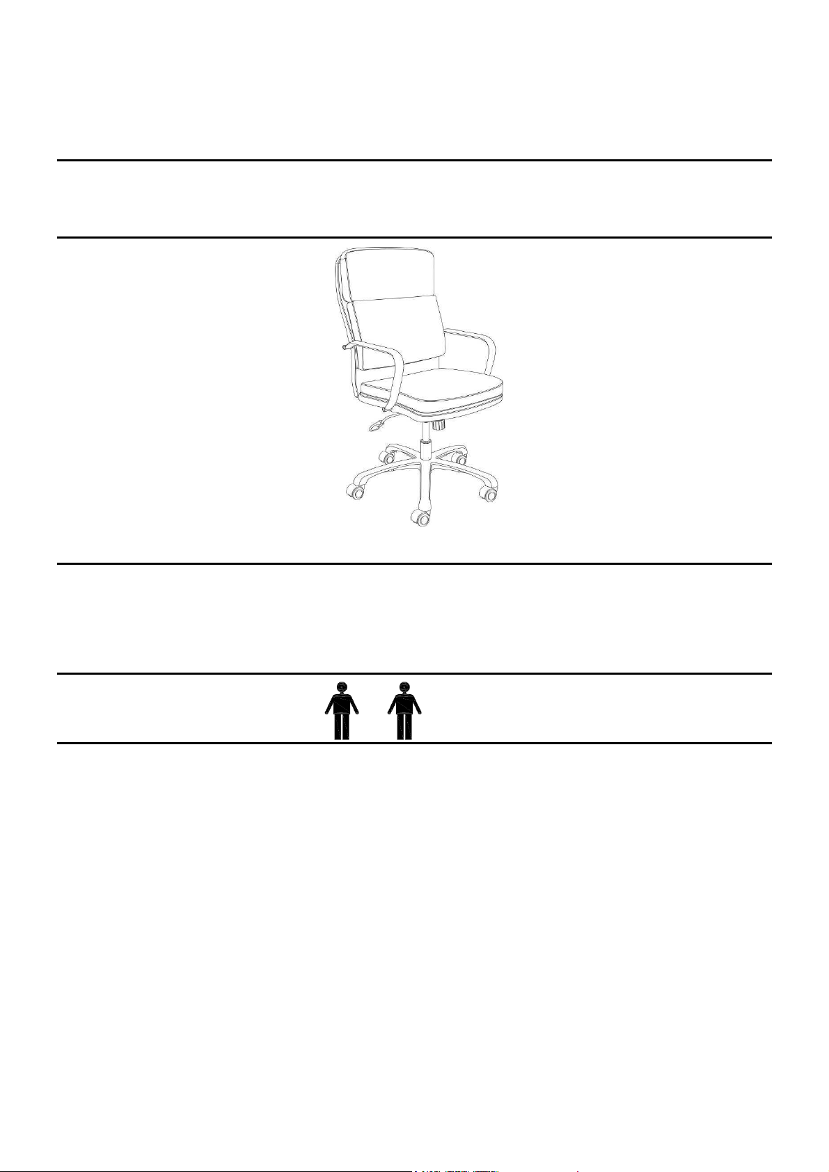
John Lewis
Amy White Chair
Stock number: 816/31165
Thank you for purchasing this product. Please read the instructions carefully before use to ensure safe
and satisfactory operation of this product.
Pre-assembly preparation
Please ensure instructions are read in full before attempting to assemble this product.
Necessary Tools
Please check the pack contents before attempting to assemble this product. A full checklist of parts is
given in this leaflet. If any parts are missing, broken, damaged, or worn, stop using this product until
repairs are made and factory replacement parts are installed. You may obtain replacement parts by
calling 0-800-051-6775 (UK).
Please note that a receipt is required for all warranty replacements. Service hours are: UK Standard
Time: 2:00 pm-1:00 am Monday – Friday.
This product is HEAVY, it should be assembled as near as possible to the point of use. TAKE CARE
WHEN LIFTING to avoid personal injury and (or) damage to the product.
This product takes approximately 20 MINUTES to assemble with 2 PEOPLE.
The fittings pack contains SMALL ITEMS which should be KEPT AWAY FROM YOUNG
CHILDREN.
Read this leaflet in full before commencing assembly.
1
Page 2
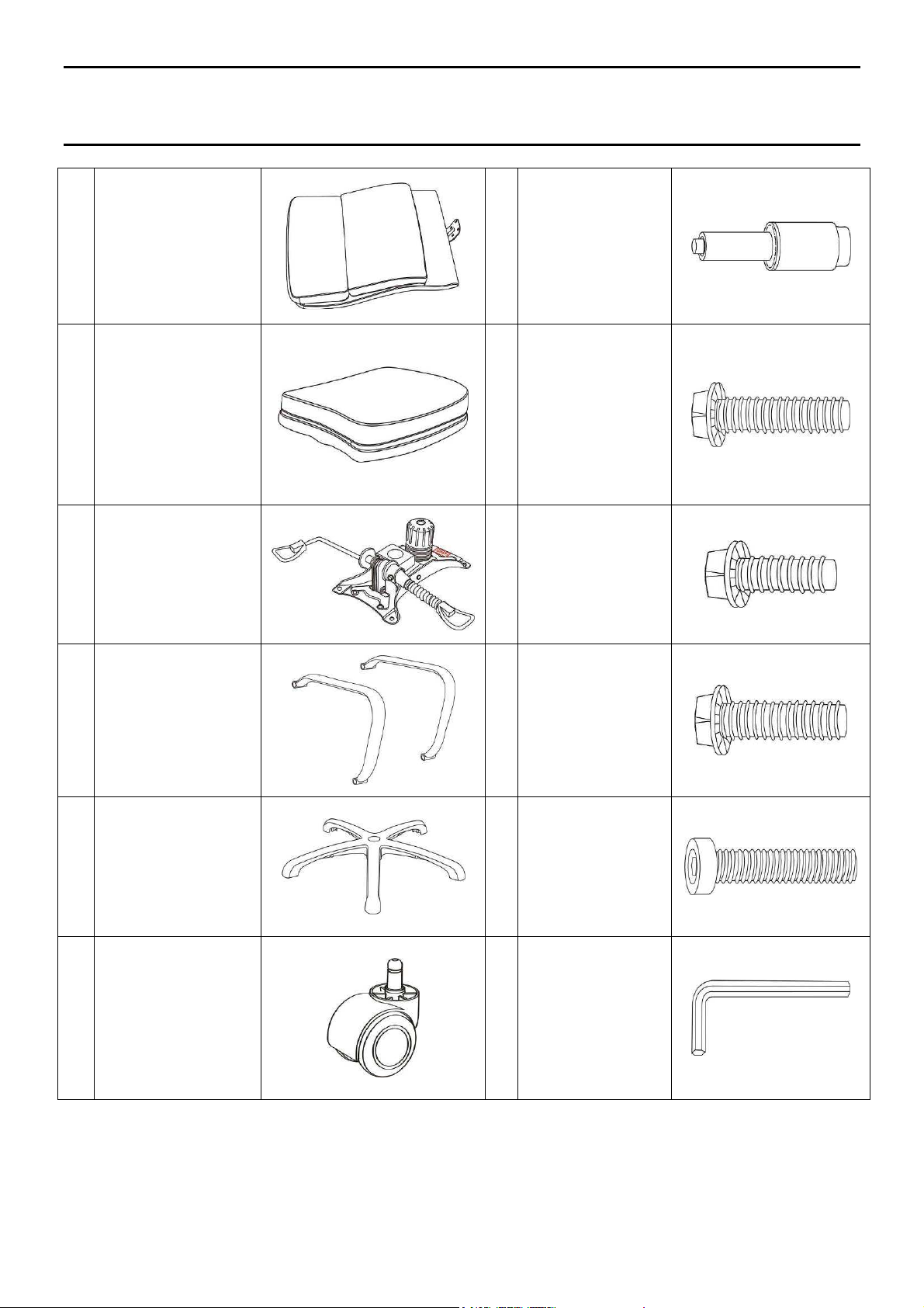
Fittings and parts checklist
A
B
C
Back Cushion
x 1
Seat Cushion
x 1
Seat Plate x1
G
H
I
Gas Lift
x 1
1-3/8” Screws
x 2
7/8” Screws
x 2
D
E Base x 1
F Casters x 5
Arm x 2
1-1/4” Screws
J
K
L
x 4
1-3/4” Screws
x 4
Allen Key x 1
2
Page 3
Step by step assembly instructions
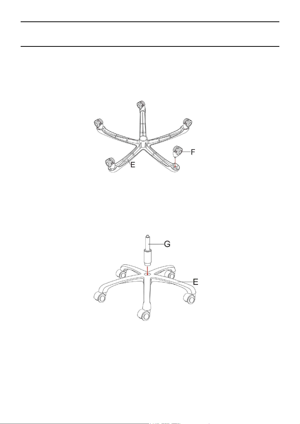
Step One
1. Turn the base (E) upside down on a protective surface, press the casters (F) into the holes at the
end of each leg.
______________________________________________________________
Step Two
1. Turn the base (E) upright and insert the gas lift (G) into the center hole of the base (E).
3
Page 4

____________________________________________________________
Step Three
1. Place the seat plate (C) on the bottom of seat cushion (B), align the seat plate so the FRONT on
the seat plate (C) matches the FRONT label on the bottom of seat cushion (B), insert the 1-3/8”
screws (H) into the front holes of seat plate (C) and 7/8” screws (I) into the rear holes of seat
plate (C), tighten the screws by using the Allen Key (L).
__________________________________________________________
Step Four
1. Place the back cushion (A) on a protective floor, put the seat cushion (B) with seat plate (C) on a
right angle and assemble the back support plate on back cushion (A) over the seat plate (C)
by using 1-1/4” screws (J) with Allen Key (L). Do not tighten the screws completely.
4
Page 5

______________________________________________________________
Step Five
1. Place the assembled chair on top of gas lift (G) and press down untill fully engaged.
_________________________________________________________
Step Six
1. Assemble the arms (D) onto the sides of the seat cushion (B) and back cushion (A) by using 1-3/4”
screws (K) with the Allen Key (L). Now tighten all the screws. Remember to tighten the screws on
the back support plate.
5
Page 6

Operating instructions
Chair Height Adjustment
While seated, lean forward and reach under the right side of the chair to find the handle. Lift the handle
and raise your body up slightly to allow the chair to rise to the desired height. To lower the seat, lift the
handle while applying more weight downward on the seat. The chair will descend until the handle is
released or the chair reaches the bottom position.
_______________________________________________________________
Tilt Tension Adjustment
Reach under the front center of the chair, grasp the round knob and turn counter- clockwise to make
the tilt mechanism firmer (stiffer). To make the tilt mechanism less firm, twist the knob clockwise until
the desired resistance is found.
6
Page 7

_______________________________________________________________
Tilt Lockout Operating
While seated, reach under the left side of the chair to find the handle. When the handle is placed in the
level position, leaning back to allow the chair to tilt backwards, push down the handle to lock the chair
angle while the desired position is reached.
Care and Maintenance
This chair is intended to be used in the office or home.
If components are missing, broken or damaged, stop use of the product until repairs are made.
Use only factory authorised components as replacements. (Please see contact details on page 1)
Please use a damp cloth with washing up liquid or soft soap and leave it natural drying when cleaning
chair surface.
Safety Instructions
WARNING: Failure to follow these warnings could result in injury!
Sit on the chair to use the weight of the body to tighten the joint on the gas lift and the seat.
Please note this is not a permanent fit due to the rise & fall and 360 degree turning action.
Always take care and keep feet clear of base when moving / lifting this product.
Check all bolts, screws and knobs every 90 days. Retighten if any are loose.
Do not stand on chair or use as a step ladder as this may cause serious injury.
Do not use the chair if any part appears damaged, broken or missing.
Do not use the chair unless all components are correctly fitted and adjusted.
The chair is designed for one person to use at a time.
The chair has been tested and approved for users weighing up to 225 lbs (102kg).
The chair is NOT recommended for use by individuals weighing more than 225 lbs (102kg).
7
Page 8

PLEASE KEEP THESE INSTRUCTIONS FOR FUTURE REFERENCE
J
ohn Lewis Partnership 171 Victoria Street London SW1E 5NN
www.johnlewis.com
8
 Loading...