

Page 1
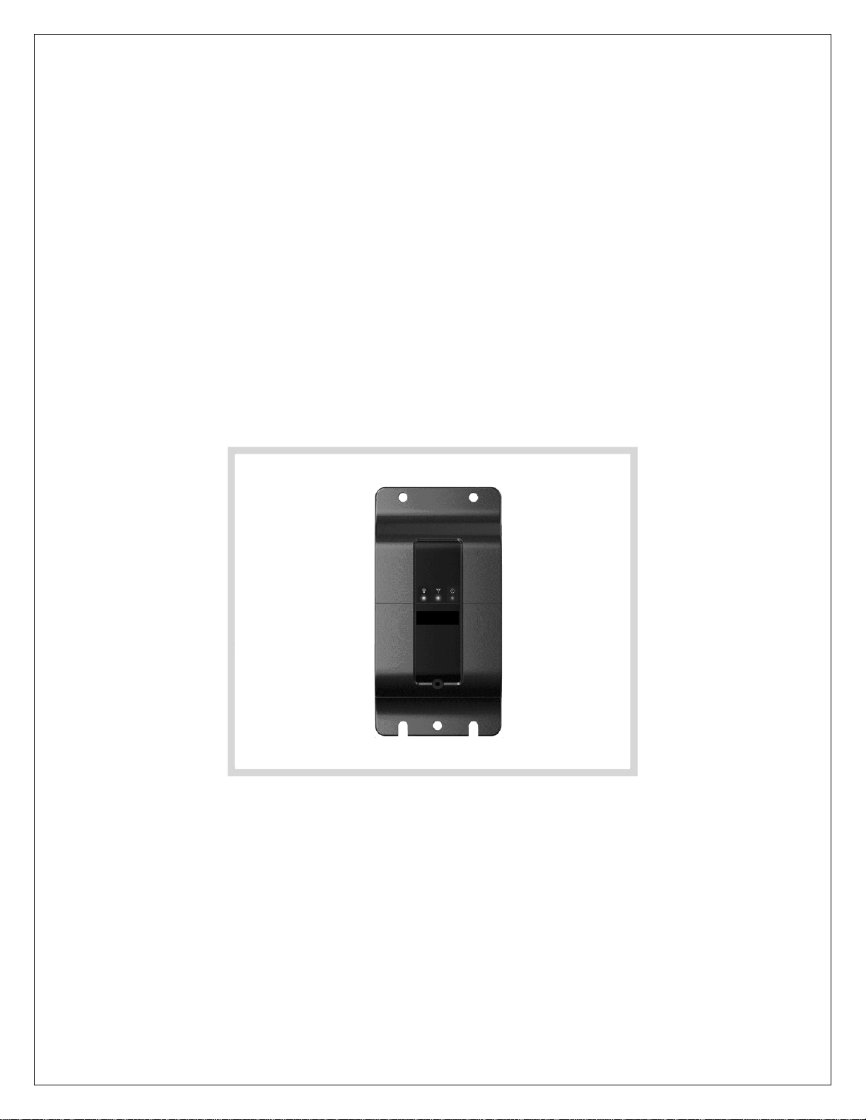
CDMA GPS Mobile Terminal
Installation Manual
Model: GPS200MV
K&L Technology Co., Ltd
Page 2

2
CONTENTS
1. Safety Information .……………………. 3
2. General Specifications ………………...…. 4
3. Unpacking .…………………… 5
4. Appearance ……………………… 6
5. Installation Manual …………………….. 8
6. Troubleshooting .……………………. 17
Page 3

3
1. Safety Information
Product care and maintenance
• Use only Manufacturer-approved accessories; otherwise, it
could damage this unit and may be dangerous.
• Do not disassemble this product. Take it to a qualified
service technician wh en repair work is required.
• The product should be kept away from heat sources.
• Do not drop.
• Do not subject this product to mechanical vibration or shock.
• This product is not water-resistant. Keep it dry.
If the product is immersed in “Water” or used in a very humid
place, the parts or circuit may get damages, causing an
electric shock or failure. Not be given free service for any
defect which is caused due to water.
Qualified service
• Only qualified service personnel may install or repair your
device.
Page 4
4
Backup Battery
12V
2. General Specifications
Model Name GPS200MV
Technology CDMA 800MHz
GPS Stand-Alone
Dimension 61(W) x 120(H) x 24(D)mm
Weight 97g (approximately with standard battery)
Operation Temp. -30°c ~ +100°c
In put Power DC
GPS Antenna Dual PIFA Type 50Ω Intenna
Li-lon 1250mAH
About 14 hours
Page 5
5
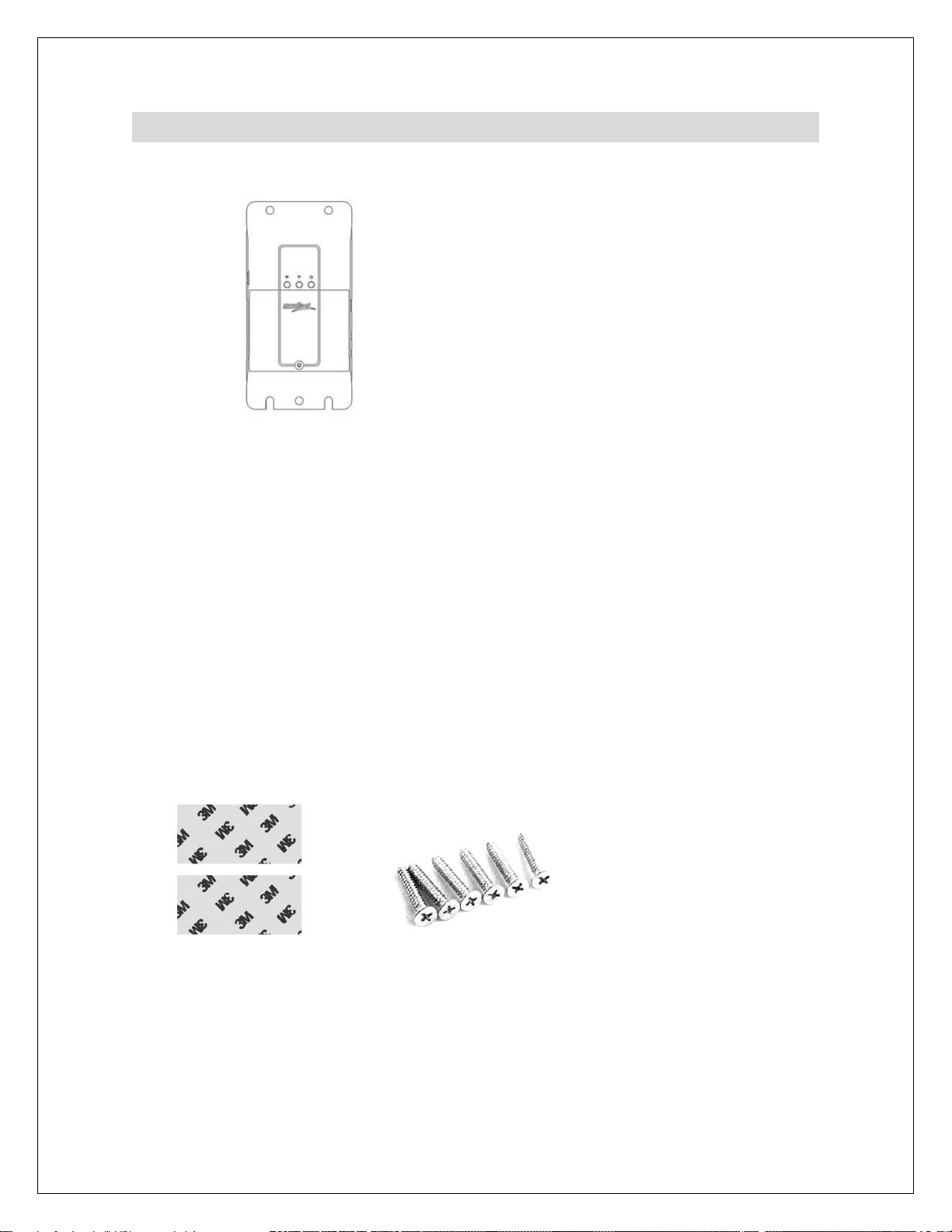
Device
(Power Cable)
3. Unpacking
Adhesive Tape
(Battery) Manual
Screws
(Fuse)
Page 6
6
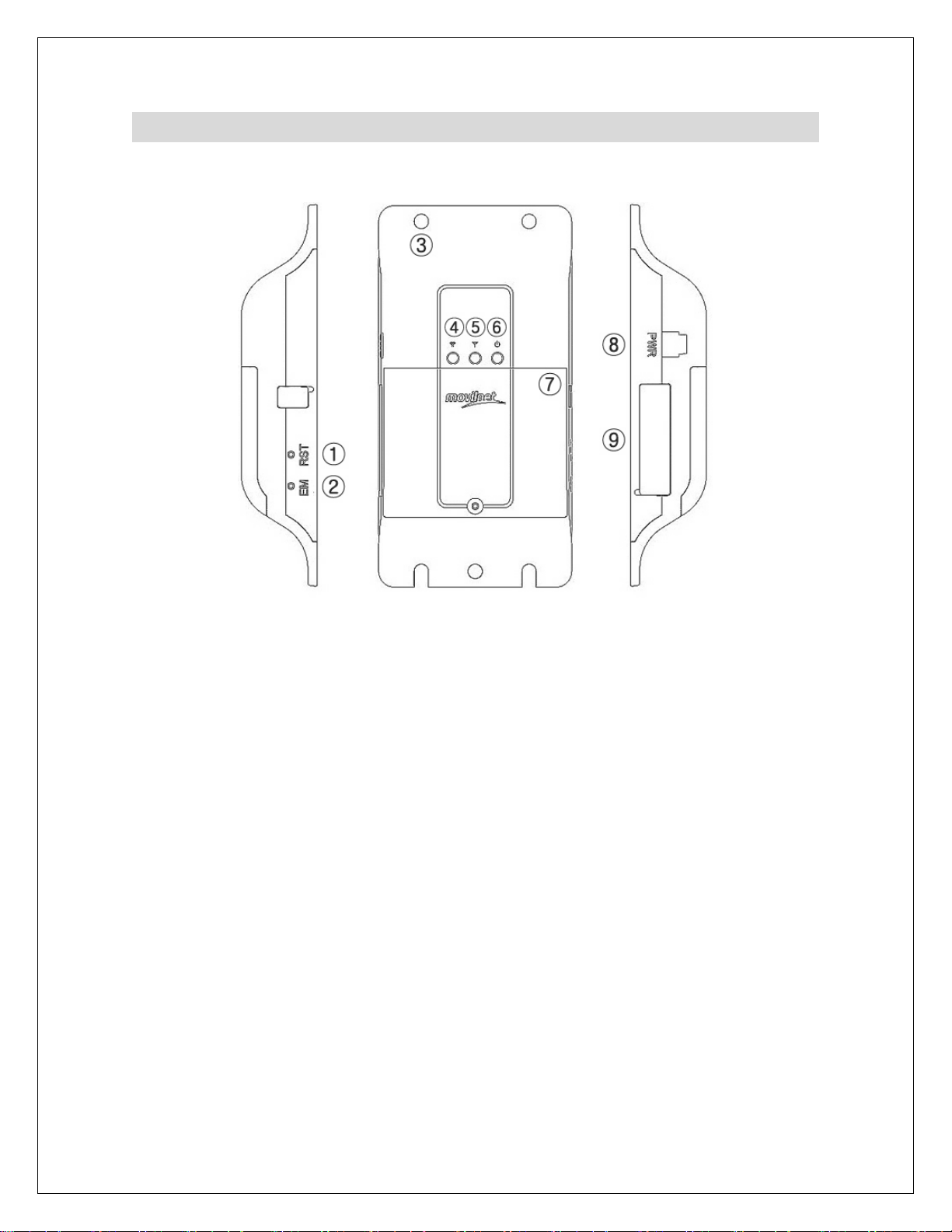
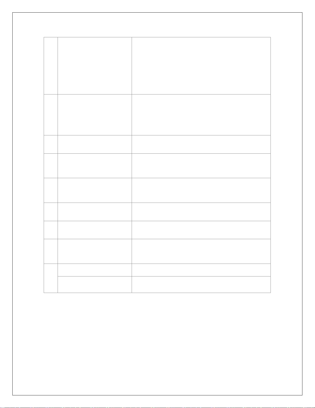
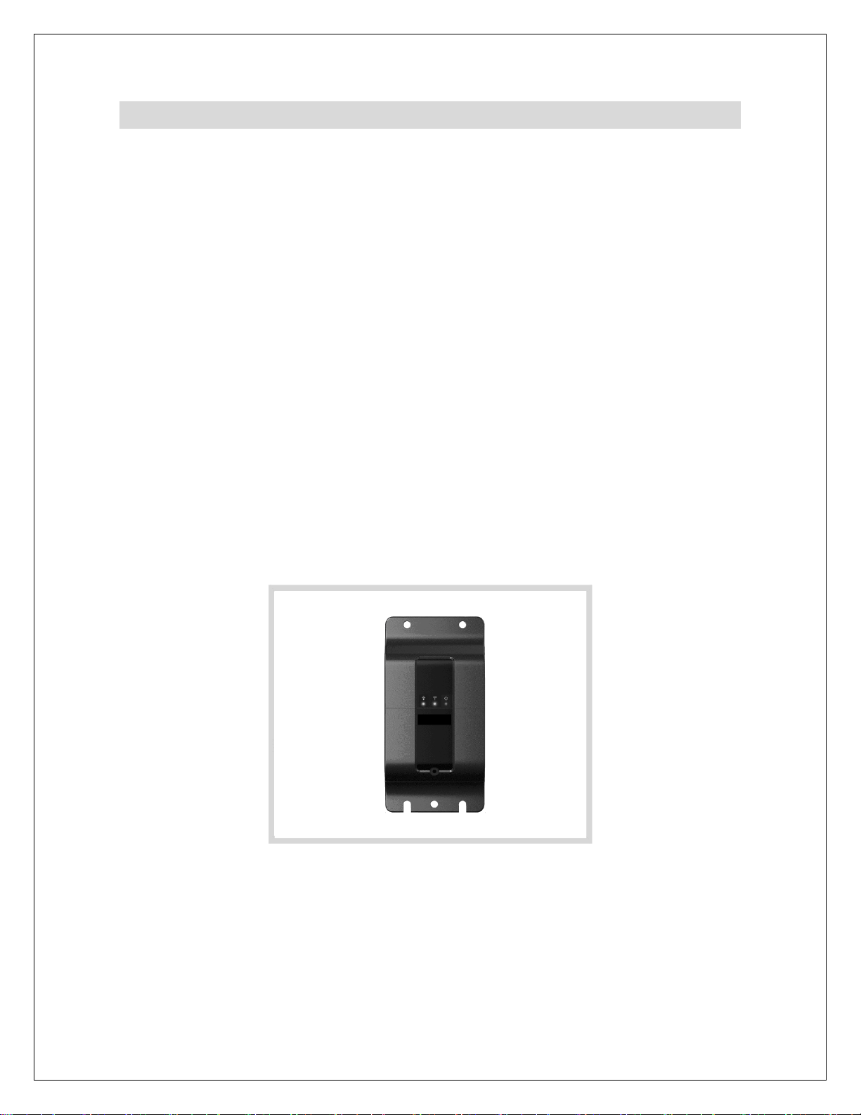
4. Appearance
① Power Button
② Emergency Re set
③ Screw Hole
④ GPS Lamp
⑤ CDMA Lamp
⑥ Power Lamp
⑦ Battery Cover
⑧ Power Connector
⑨ 24pin Connector
4pin Car Alarm Box Connector
Page 7
7
the lamp will be turned on green and
24pin Connector
4pin Car Alarm Box
Power Button If you want to turn on the device, push
①
the power button for 2 seconds at
least.
You can realize that the device power
on or not through the lamp.
It's the same way to turn off the
device.
Emergency Reset
②
Screw Hole By using screws, you can fix a device
③
GPS Lamp When a device takes GPS air-signal,
④
CDMA Lamp
⑤
When you need an emergency
download, you have to use this button.
The way is that push the emergency
reset button and push the power
button meanwhile.
to your car tightly.
the lamp will be turned on orange color
and blink.
When a device takes CDMA air-signal,
blink.
Power Lamp When a devic e power on, t he lamp wi ll
⑥
be turned on red.
Battery Cover To open cover, you should get rid of a
⑦
screw first.
Power Connector Using enclosed power cable, you
⑧
should connect device to car constant
power (Battery).
⑨
Connector
Software download
Connect to car alarm box
Page 8
8
5. Installation Manual
The installation location can be changed according to
the user’s preferences.
This manual recommends user to install using “Car
main power” for keeping permanent activation.
• Connecting power supply
Use the wire connected to the car main power for power
supply.
• Preparing the product
Make sure the positive (+) and negative (–) wire end of the
product.
• Connect the wire of product to car main power. At this time,
watch out the (+) and (–) polarity.
• The product is connected normally, if you can see the light
turned on the product.
• Finish the insulated wires by winding them with a tape
neatly, in order to prevent an electric leakage or short circuit.
Page 9

9
• Installation
Install the product at the proper location inside of the car
where dust was removed and cleaned. The product can be
fixed using the tape attached to the rear side of the product
or the screw holes at both sides of the product. (At this time,
attach the product in such way that the LCD window faces
upwards for proper GPS reception.)
• Finishing
When the product is installed, the product is not seen by the
users with their naked eyes. And the product should be kept
away from heat sources.
Page 10
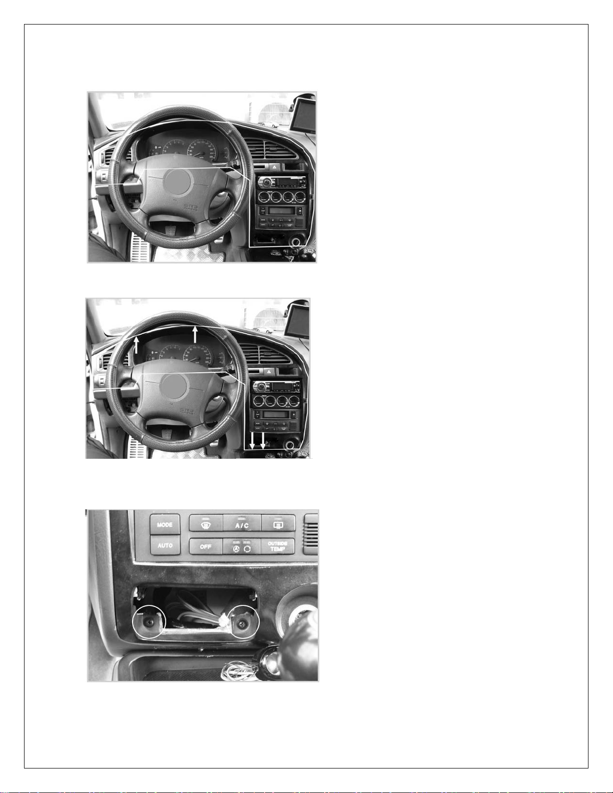
1. Take center fascia apart from dashboard
1-1 Unscrew the center fascia marked.
1-2 Unscrew the center fascia marked.
It may differ slightly depending on the model
10
Page 11
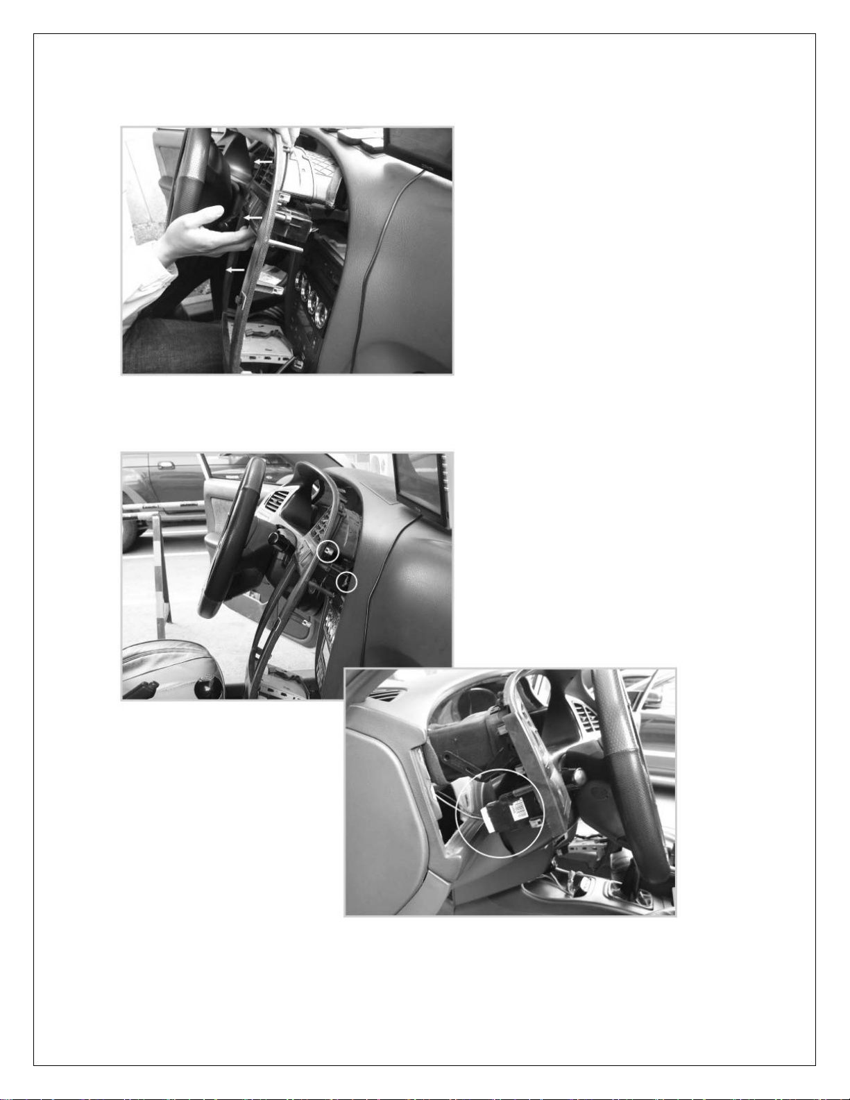
1-3 Pull the separated center fasc ia toward your body.
1-4 Pull out the connector between the center fascia and
dashboard.
11
Page 12
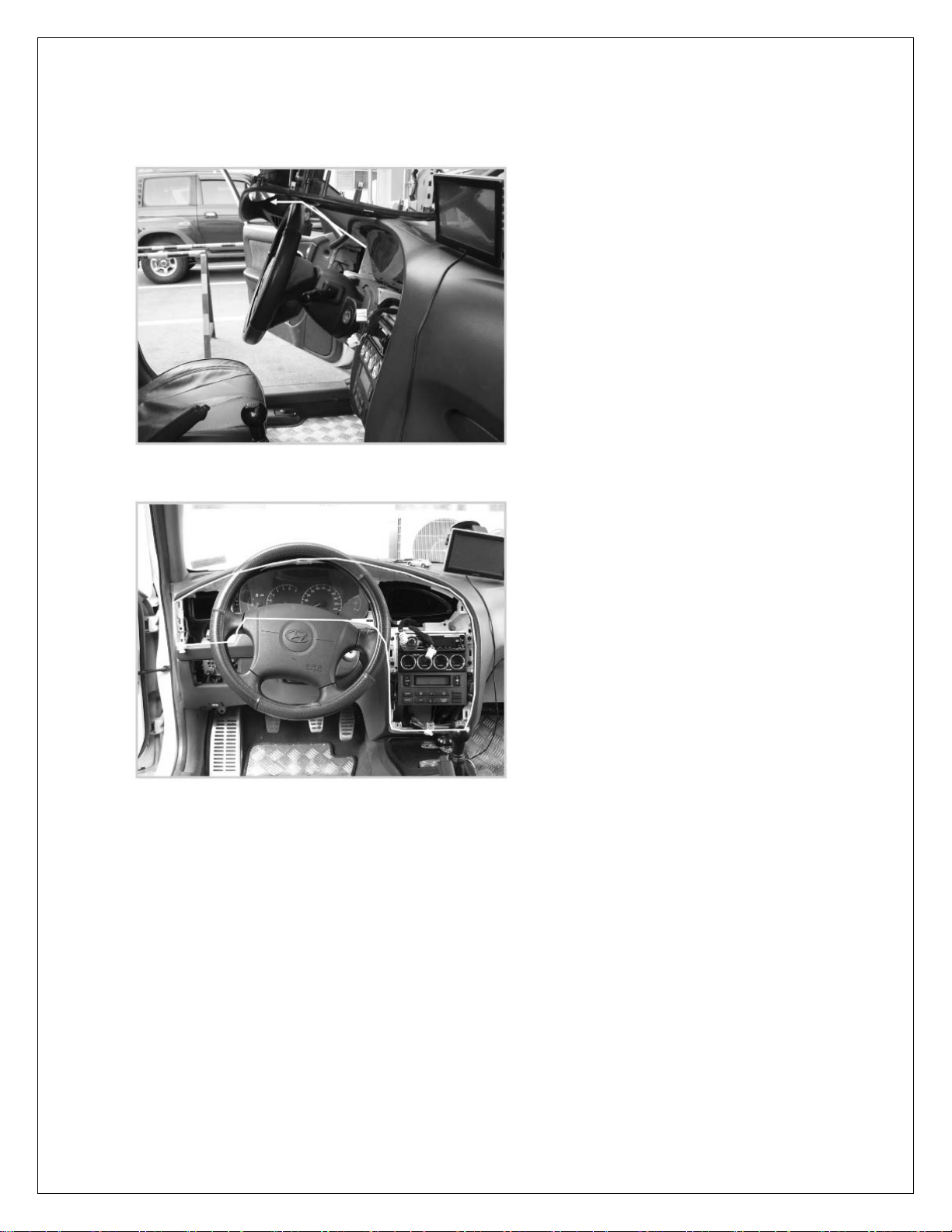
1-5 After the all connectors remove completely, take the
separated center fascia up onto the handle.
1-6 As the below picture, remove the center fascia completely.
2. Power supply connection
Use the car main power adapt er as the power supply.
2-1 Peel the rubber tube off the car main power adapter wire
12
Page 13
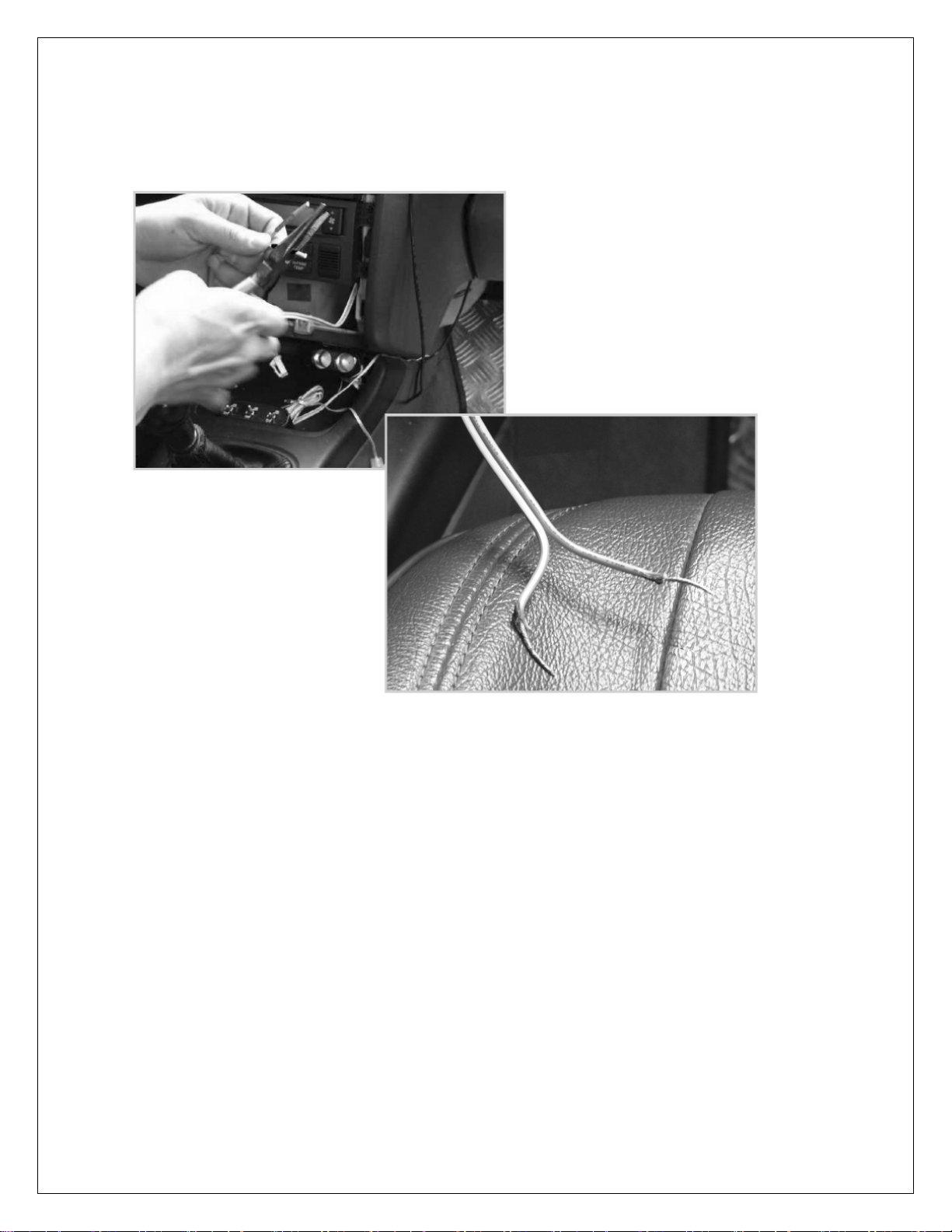
3. Prepare the GPS device for installation.
As the below picture, peel the rubber tube off the (+) and (-)
pole
3-1 The copper cable of car main power adapter and GPS
device connect to each other keeping attention the polarity.
3-1-1 The polarity of GPS device
Red colored wire is positive (+) pole.
Black colored wire is negative (-) pole.
When you purchase the device, you can see the attached ring.
Depending on the type of car, cut the ring off.
13
Page 14
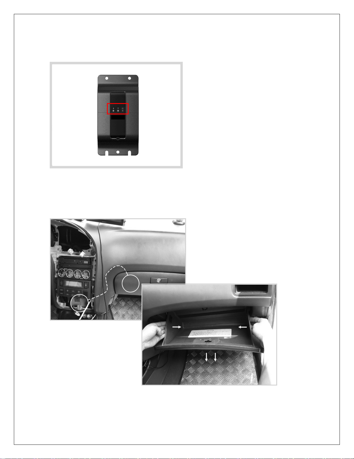
3-2 After the all wires are connected, the device should be
lights up as below.
3-3 Insulate the peeled wires using an insulating tape.
4. Push the device deeply into the center fascia and move to
glove box.
5. As the below picture, open the glove box fully pushing the
side.
14
Page 15
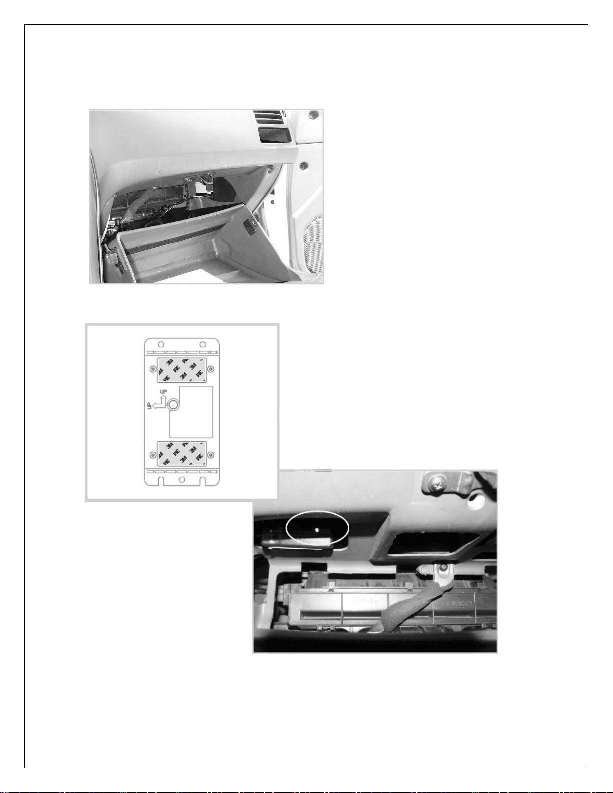
5-1 To stick the device on glove box, remove a dust and keep
clean inside of glove box.
6. Remove the label of adhesive tape.
Installation 1 >
7. Stick the device on suitable position.
15
Page 16
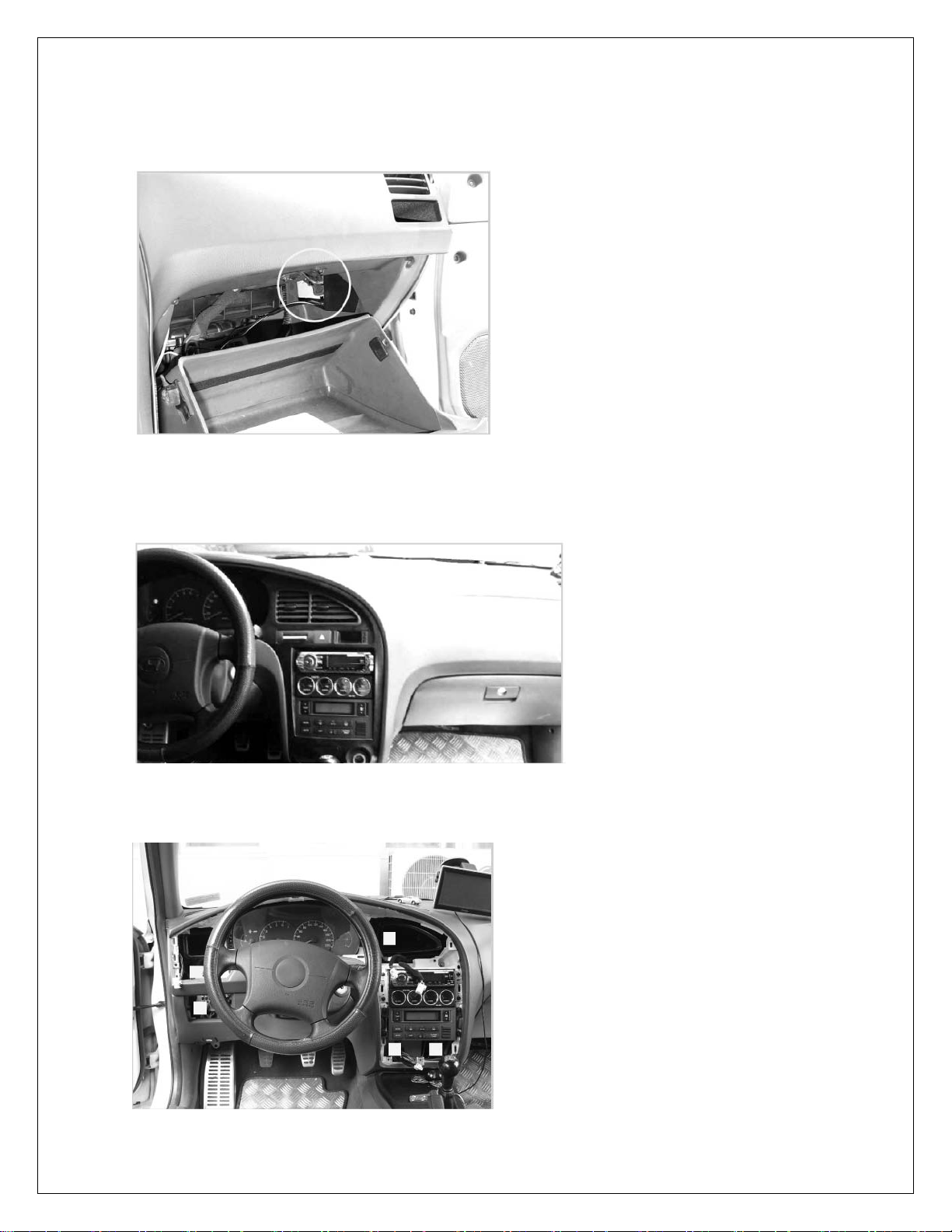
7-1 When the device is stuck, keep out of touch with glove
box’ s door.
< Installation 2
8. Finish
Put together the center fascia and dashboard in reverse order
of disassemble.
9. As the below picture, you can choice the install position
anywhere you want.
16
Page 17

6. Troubleshooting
Please check to see if any problem which you may have with
your phone is described here before taking it for service or
calling a service engineer.
• Check whether you connect the wire of product to car main
power correctly.
• Charging adapter is connected normally, if you can see the
light turned on the product.
• This manual recommends user to install using “Car main
power” for keeping permanent activation.
• For your positioning service, it can take some time to
connect between GPS termina l and satellite.
• A cloudy day or high buildings may affect the ability to
service.
• A sudden climate change may affect the ability to service.
17
Page 18

Model: GPS200MV
(REV 1.0)
18
Page 19
FCC (Federal Communications Commission)
Information to User
This equipment has been tested and found to comply with the limits for a Class B digital device, pursuant to Part 15 of the
FCC Rules. These limits are designed to provide reasonable protection against harmful interference in a residential
installation.
This equipment generates uses and can radiate rad io frequency energ y and, if not installed and us ed in accordance with
the instructions, may cause harmful interference to radio communications.
However, there is no guarantee that interference will not occur in a part icular installation. If this equipment does cause
harmful interference to radio or television reception, which can be determined by turning the equi pment off and on, the
user is encouraged to try to correct the interference by one or more of the following measures:
- Reorient or relocate the receiving antenna.
- Increase the separation between the equipment and receiver.
- Connect the equipment into an outlet on a circuit different from that to which the receiver is connected.
- Consult the dealer or an experienced radio/TV technical for help.
Caution
1. This equipment may generate or use radio frequenc y e nerg y. Ch ange s or modific atio ns to this equi p ment ma y caus e
harmful interference unless the modifications are expressly approved in the instruction manual. The us er could lose
the authority to operate this equipment if an unauthorized change or modification is made.
2. In order to meet RF Maximum permissible Exposure Safety Guidelines, a minimum distance of 20Cm shall be
maintained between this device and personnel during transmitter operation.
 Loading...