

FFoorrccee
44
G6 RAID System
6-bay Desktop Enclosure
Installation Guide
May 29, 2002 • Revision B
Patent Pending

FORTRAForce4G6 Installation Guide Rev B
ii
Copyright
Copyright 1998, 1999, 2001 by JMR Electronics, Inc. All Rights Reserved. No part of this publication may
be reproduced, transmitted, transcribed, stored in a retrieval system, or translated into any language, in any form
or by any means, electronic, mechanical, photocopying, recording or otherwise, without the express written
permission of JMR Electronics, Inc.
Sales and Ordering Information
JMR Electronics, Inc.
20400 Plummer Street
Chatsworth, CA 91311 USA
Phone: 818-993-4801
Fax: 818-993-9173
Office Hours: Monday-Friday 8:00 A.M. to 5:00 P.M., Pacific Standard Time
European Corporate Headquarters
JMR Electronics United Kingdom
Iain Pickthall
P.O. Box 3058 Wokingham
Berkshire - RG40 3FU - United Kingdom
Phone: + 44-118-973-6018
Fax: + 44-118-973-7191
E-Mail: Iain@jmr.com
Internet: http://www.jmr.com
Trademarks
JMR, the JMR logo, and FORTRAare registered trademarks of JMR Electronics, Inc. All other product and
brand names are the property of their respective holders.
Changes
The material in this document is for information only and is subject to change without notice. JMR Electronics,
Inc. reserves the right to make changes to this manual and the equipment described herein without notice. JMR
has made all reasonable efforts to ensure that the information in this manual is accurate and complete. However,
JMR shall not be liable for any technical or editorial errors or omissions made herein or for incidental, special,
or consequential damage of whatsoever nature resulting from the furnishing of this manual, or operation and
performance of equipment with this manual.
Disclaimer
The original product packaging has been tested and is safe under normal shipping circumstances. Reshipping
the product without using the original product packaging will void the warranty. Do not ship the unit with
canisters or power supplies installed as this will void the warranty and could cause damage to the unit and drives.
The canisters should be packaged separately within the product packaging as provided.
FCC Information
The FORTRAequipment generates, uses and can radiate radio frequency energy. If the FORTRAArray is
not installed and used properly (that is, in strict compliance with these instructions), it may cause interference to
radio and television reception.
The FORTRAequipment and its contents are designed to comply with the limits for a Class A computing
device in accordance with the specifications in Part 15 of FCC rules. These rules are designed to provide
reasonable protection against radio interference in a commercial installation. However, there is no guarantee
that interference will not occur in a particular installation. Operation of this equipment in a residential area is
likely to cause interference, in which case the user, at his own expense, will be required to take whatever
measures are necessary to correct the interference.
Y ou may find the FCC booklet, How to Identify and Resolve Radio Interference Problems, helpful. This booklet
is available from the U.S. Government Printing Office, Washington, DC 20402. Stock #004-000-00345-4.
Printed in the USA
Part Number PUB-00282
Revision B, May, 2002 SCS
Patent Pending
WARNING: Changes or modifications, not expressly approved by the
manufacturer, could void the user's authority to use the equipment.
WARNUNG: Nicht ausdrücklich durch den Hersteller genehmigte Änderungen
oder Modifikationen können die Erlaubnis Zur benutzung der Produkte
gefährden.

FORTRAForce4G6 Installation Guide Rev B
iii
Table of Contents
1. Introduction
2/4/6/8/10/12/15-bay Product Family Features . . . . . . . . . . . . . . . . . . . . .1-1
6-bay Desktop Specifications . . . . . . . . . . . . . . . . . . . . . . . . . . . . . . . . . .1-2
Fibre Channel Features . . . . . . . . . . . . . . . . . . . . . . . . . . . . . . . . . . . . . .1-2
Loop Expansion . . . . . . . . . . . . . . . . . . . . . . . . . . . . . . . . . . . . . . . . . .1-2
Dual Loops (A & B) . . . . . . . . . . . . . . . . . . . . . . . . . . . . . . . . . . . . . .1-3
ID Selection . . . . . . . . . . . . . . . . . . . . . . . . . . . . . . . . . . . . . . . . . . . . .1-3
2. Hardware Specification
Environmental Specifications . . . . . . . . . . . . . . . . . . . . . . . . . . . . . . . . . .2-1
Electrical Specifications . . . . . . . . . . . . . . . . . . . . . . . . . . . . . . . . . . . . . .2-1
Agency Compliance . . . . . . . . . . . . . . . . . . . . . . . . . . . . . . . . . . . . . . . . . .2-1
Packaging Specifications . . . . . . . . . . . . . . . . . . . . . . . . . . . . . . . . . . . . . .2-1
Disclaimer . . . . . . . . . . . . . . . . . . . . . . . . . . . . . . . . . . . . . . . . . . . . . .2-2
Thermal Specifications . . . . . . . . . . . . . . . . . . . . . . . . . . . . . . . . . . . . . . .2-2
Rotation Vibration Specifications . . . . . . . . . . . . . . . . . . . . . . . . . . . . . . .2-2
Fault Indication Features . . . . . . . . . . . . . . . . . . . . . . . . . . . . . . . . . . . . . .2-2
Fault Indicators . . . . . . . . . . . . . . . . . . . . . . . . . . . . . . . . . . . . . . . . . .2-2
Audible Alert . . . . . . . . . . . . . . . . . . . . . . . . . . . . . . . . . . . . . . . . . . . .2-2
3. Device Installation
SCA Connection and Hot-Swapping . . . . . . . . . . . . . . . . . . . . . . . . . . . .3-1
Locking/Unlocking . . . . . . . . . . . . . . . . . . . . . . . . . . . . . . . . . . . . . . . . . .3-1
Canister Removal/Insertion . . . . . . . . . . . . . . . . . . . . . . . . . . . . . . . . . . . .3-1
Drive Installation . . . . . . . . . . . . . . . . . . . . . . . . . . . . . . . . . . . . . . . . . . . .3-2
4. Fibre Channel Setup
Default Slot ID . . . . . . . . . . . . . . . . . . . . . . . . . . . . . . . . . . . . . . . . . . . . .4-2
Setting Slot ID . . . . . . . . . . . . . . . . . . . . . . . . . . . . . . . . . . . . . . . . . . . . .4-2
Option Settings . . . . . . . . . . . . . . . . . . . . . . . . . . . . . . . . . . . . . . . . . . . . .4-4
Rear I/O Connections . . . . . . . . . . . . . . . . . . . . . . . . . . . . . . . . . . . . . . . .4-4
CH-A 1 . . . . . . . . . . . . . . . . . . . . . . . . . . . . . . . . . . . . . . . . . . . . . . . . .4-5
CH-A 2 . . . . . . . . . . . . . . . . . . . . . . . . . . . . . . . . . . . . . . . . . . . . . . . . .4-5
CH-B 1 . . . . . . . . . . . . . . . . . . . . . . . . . . . . . . . . . . . . . . . . . . . . . . . . .4-5
CH-B 2 . . . . . . . . . . . . . . . . . . . . . . . . . . . . . . . . . . . . . . . . . . . . . . . . .4-5
System Fault Audible Alert . . . . . . . . . . . . . . . . . . . . . . . . . . . . . . . . .4-5
Alarm Reset . . . . . . . . . . . . . . . . . . . . . . . . . . . . . . . . . . . . . . . . . . . . .4-5
Table of
Contents

5. Blower Operation
Blower Removal/Insertion . . . . . . . . . . . . . . . . . . . . . . . . . . . . . . . . . . . . .5-1
Blower Replacement . . . . . . . . . . . . . . . . . . . . . . . . . . . . . . . . . . . . . . . . .5-2
6. Power Supply Operation
Power Supply Removal/Insertion . . . . . . . . . . . . . . . . . . . . . . . . . . . . . . .6-1
Power Supply Replacement . . . . . . . . . . . . . . . . . . . . . . . . . . . . . . . . . . . .6-2
7. Installing the Intel PCI RAID Controller
Installing the PCI Controller . . . . . . . . . . . . . . . . . . . . . . . . . . . . . . . . . . .7-1
Configuring RAID Sets . . . . . . . . . . . . . . . . . . . . . . . . . . . . . . . . . . . . . . .7-1
8. Product Support
US Corporate Headquarters . . . . . . . . . . . . . . . . . . . . . . . . . . . . . . . . . . . .8-1
Manual Changes . . . . . . . . . . . . . . . . . . . . . . . . . . . . . . . . . . . . . . . . . . . .8-1
Appendix A. Drive and Controller Manufacturers
Drive Manufacturers . . . . . . . . . . . . . . . . . . . . . . . . . . . . . . . . . . . . . . . . .A-1
RAID Controller Manufacturers . . . . . . . . . . . . . . . . . . . . . . . . . . . . . . . .A-1
Host Bus Adapter Manufacturers . . . . . . . . . . . . . . . . . . . . . . . . . . . . . . .A-2
FORTRAForce4G6 Installation Guide Rev B
iv

FORTRAForce4G6 Installation Guide Rev B
1-1
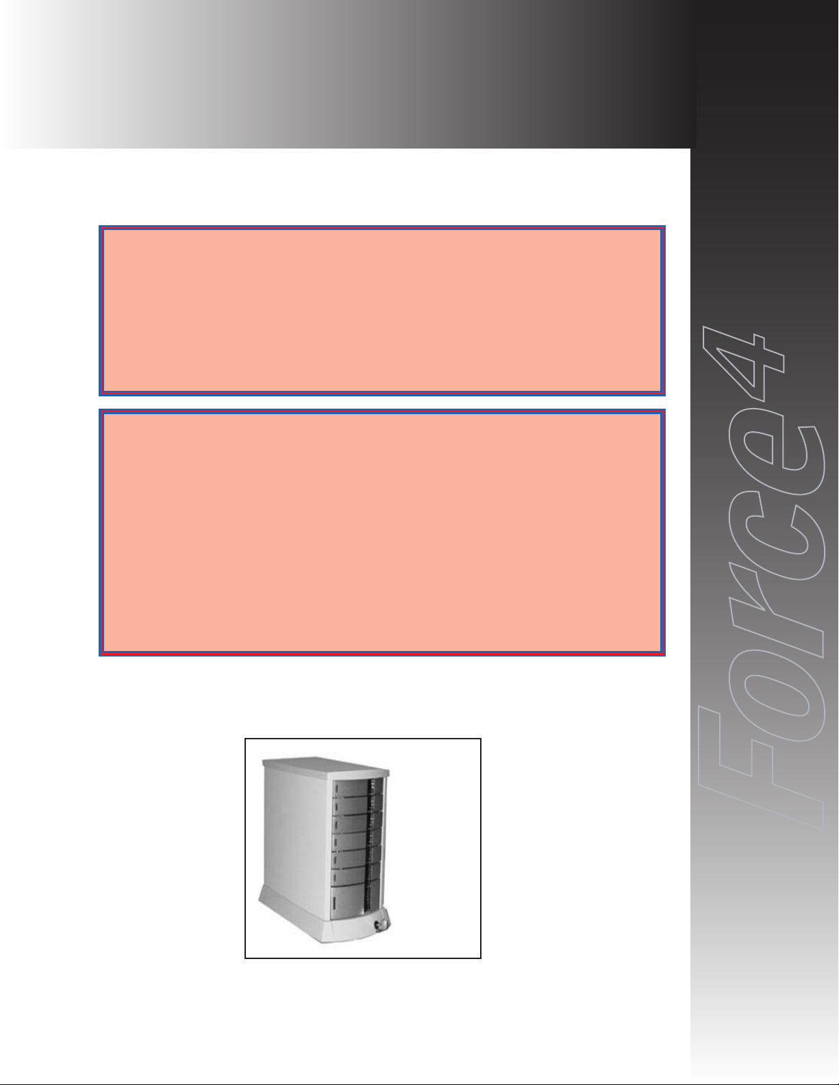
The FORTRA
FFoorrccee
44
G6 RAID System is designed for use with a host system
to provide a high-end desktop RAID storage solution. The following is a
summary of the G6 RAID System features:
• The FORTRA
FFoorrccee
44
G6 RAID System is a six drive Desk Top
enclosure that supports up to six 3.5" LP (Low-Profile) SCA (40-pin)
drives. The Fibre Channel uses SFP transceiver connections to connect
to an Intel PCI Fibre Channel 2 RAID controller supporting RAID 0 and
1. The G6 RAID System also includes four Seagate 36G or 73G HDDs.
2/4/6/8/10/12/15-bay Product Family Features
FORTRAand StorBladeTMare families of high-end enclosures designed for
high-volume performance storage solutions. The following table shows the
features of the FORTRA
2/4/6/8/10/12/15-bay and StorBladeTMproducts.
1. Introduction
2-bay
4-bay
1,3
6-bay
*1,3
8-bay110-bay
*1,2
12-bay
15-bay
*1,3
StorBlade
Number of Device Bays 2 4 6 8 10 12 15 4
Number of Blowers 1 1 1 or 2 2 2 2 2 2
Number of Power Supplies 1 1 1 or 2 2 2 2 2 1 or 2
Number of I/O Channels (SCSI Only) 1 1 2 2 2 2 2
SCSI SE/LVD Supported
2 2 2 2 2 2 2
Fibre Channel Supported
2 2 2 2 2 2
Hot-Swap Canisters
2 2 2 2 2 2 2 2
Removable Power Supplies
2 2 2 2 2 2 2
Fibre only
Removable Blowers
2 2 2 2 2 2 2
Fibre Only
N+1 Power Supplies
2 2 2 2 2
Fibre only
N+1 Blowers
2 2 2 2 2 2
MIA Support (FC Only)
2 2 2 2
Loop Expansion Support (FC Only)
2 2 2 2 2 2
Daisy Chainable (SCSI Only)
2 2 2 2 2 2
Built-in Termination (SCSI Only)
2 2 2 2
Auto Termination (SCSI Only)
2 2 2 2
SAF-TE/SES Ready (Optional)
2 2 2 2
Fibre only
SAF-TE/SES Compatible
2 2 2 2
Fibre only
SCSI to SCSI RAID Support
2 2 2 2
Fibre to SCSI RAID Support
2 2
Fibre to Fibre RAID Support
2 2 2
Fibre to ATA RAID Support
2
SCSI to ATA RAID Support
2
(D)esktop/(T)ower/(R)ackmount D D DTR T TR R TR R
* 6/10/15-bay unit features apply to both Tower and Rackmount models
1 Features are based on a standard configuration with no internal host controller(s) installed
2 Fibre channel 10/15-bay enclosures have built-in SES
3 Fibre Channel 2Gb Model available. 2Gb models use SFP transceivers.

FORTRAForce4G6 Installation Guide Rev B
1-2
FORTRA
FFoorrccee
44
products use advanced mid-plane technology developed by
JMR, that allows power supplies, drives, and all other enclosure components to
interface into a single board. This provides superior performance and easy
connectivity.
The FORTRA
FFoorrccee
44
G6 RAID System host interface supports 2G Fibre
Channel interfaces as long as the drives have SCA connectors. Connection to the
Intel PCI Fibre Channel 2 host system is made using SFP transceiver connectors.
FORTRA
Force
4
G6 RAID System Components
The FORTRA
FFoorrccee
44
G6 RAID System includes the following components:
One - 6-Bay 2G Fibre Desk Top enclosure
One - Intel PCI Fibre Channel 2 RAID controller
Four - Seagate 36G or 73G HDDs
Two - 2G Copper Fibre Cables (HSSDC to HSSDC2)
6-bay Desktop Specifications
Dimensions/Weight
Unit Weight 19.7 lbs. (9.0kg)
Height 11-1/2" (292mm)
Width 7-3/4" (197mm)
Depth 12-1/2" (316mm)
Power Supply
Quantity: 1
Power: 300 Watts
Input: 115-230 VAC; 50-60Hz (auto-switching)
Output: +5V @ 20A
+12V @ 17A
Blower
Quantity: 1
Size: 125mm (4.92") each
Air Flow: 27.2CFM (0.76m
3
/min)
Noise: 51dB(A)
Fibre Channel Features
Loop Expansion
FORTRAFibre Channel enclosures include a loop expansion I/O connector on
each port.

Dual Loops (A & B)
A single loop is required for unit operation however both loops can be used to
connect to different hosts, dual host adapters, and other devices, for flexible and
even redundant configurations. For specific connection and installation
information, refer to Chapter 4
.
ID Selection
0-127 device ID addresses are addressable and can be easily set-up via ID jumpers
for each slot. For specific connection and installation information, refer to
Chapter 4
.
FORTRAForce4G6 Installation Guide Rev B
1-3

FORTRAForce4G6 Installation Guide Rev B
2-1
This chapter covers specification information for the FORTRA
FFoorrccee
44
G6 RAID
System enclosure.
Environmental Specifications
Operating Temperature: 5°C to 40°C (41°F to 104°F)
Storage Temperature: 0°C to 65°C (32°F to 149°F)
Maximum ambient temperature is dependent on the recommended temperature to
meet the MTBF rating as specified by the manufacturer of the installed devices.
Electrical Specifications
AC Inlet Type: IEC320/EN60320
Power Cord: NEMA5-15P
Power Supply: Auto-switching for 110/220V operation
Agency Compliance
FORTRAenclosures have been designed and built to comply with the FCC
Class A, UL, CSA/TUV, CE, and C-Tick standards. For more information on
FCC Class A compliance, see page 2.
Packaging Specifications
FORTRApackaging has been designed to be reusable and recyclable. Drives
may be installed and shipped in the canisters as long as the canisters are in their
original packaging location and are not installed in the enclosure. Shipping the
unit with canisters and/or power supplies installed in the enclosure may cause
damage to the enclosure or to the drives and will void the warranty.
Packaging complies with ISTA (International Safe Transit Association) standards
and has been ISTA certified.
Each canister is pre-packaged in an anti-static bag. Do not throw the packaging
away if the product is intended for re-shipping. When transporting or shipping a
JMR approved shipping container must be used.
SAFETY TIP: Reshipping the enclosure with canisters, drives, or power
supplies installed in the enclosure may cause damage to these
components and will void the warranty
SICHERHEITSHINWEIS: Der Versand des Gehäuses mit eingebauten
Einschüben, Platten und Netzteilen kann zur Beschädigung dieser
Komponenten führen und somit den Garantieanspruch gefährden.
2. Hardware Specification

Disclaimer
The original product packaging has been tested and is safe under normal shipping
circumstances. Reshipping the product without using the original product
packaging will void the warranty. Do not ship the unit with canisters and/or
power supplies installed in the enclosure as this will void the warranty and could
cause damage to the unit and drives. The canisters should be packaged separately
within the product packaging, as provided.
Thermal Specifications
FORTRAenclosures have been designed to meet the air-flow/cooling
requirements for popular 7,200, 10,000 and 15,000 RPM disk drives. Using a
high performance blower, air is pulled in from all open vents and exhausted out
the back of the unit.
Rotation Vibration Specifications
FORTRAenclosures have been designed to meet the rotation vibration/shock
requirements for popular 7,200, 10,000 and 15,000 RPM disk drives.
Fault Indication Features
This section reviews the indicators that will notify the user of a power supply or
blower that is in a fault state. More information is available in Chapter 5
(blowers) and Chapter 6 (power supply).
Fault Indicators
All slots will blink 'Red' in color on a blower fault. On a power supply fault, the
front power supply LED will blink on and off.
Audible Alert
On a blower or power supply fault, an audible alert will sound. Pressing the Alert
Reset button on the back of the unit will turn the alert off.
FORTRAForce4G6 Installation Guide Rev B
2-2

FORTRAForce4G6 Installation Guide Rev B
3-1
This chapter covers Fibre Channel device installation for FORTRA
FFoorrccee
44
G6
desktop enclosure.
SCA Connection and Hot-Swapping
The unit uses SCA-2 type connectors which provide a safe means of
connection/disconnection when hot-swapping devices. In order to utilize this
feature, the host adapter or RAID controller and host operating software must
support the feature. Any SCA drive is capable of plugging directly into the
backplane of the unit and should not require any additional cabling or
connections.
Locking/Unlocking
A front lock prevents unwanted removal of the canisters including the power
supply canister. Before attempting to remove any drive or the power supply,
insure that the enclosure is in the Unlocked position.
Canister Removal/Insertion
1. The photo to the right shows the canister in a locked
position.
2. Pull the handle out to unlock the canister from the
FORTRA
unit. Ensure that the thumb is placed
below the line. Pressing the thumb against the
Status LED lens could break it. Notice that the
locking tab slides down as the handle is pulled out.
3. Pull the canister straight out to remove. Ensure
that any installed devices are spun down before
full removal to prevent damage to the drive.
Follow the steps in reverse to reinstall.
SAFETY TIP: After disengaging a device from the enclosure, allow 10 seconds
before pulling the canister out of the unit. This allows the device to
properly spin/shut down before transport.
SICHERHEITSHINWEIS: Nachdem ein Einschub vom Gehäuse wie in "Step
3" gezeigt gelöst wurde, warten Sie bitte ca. 10 Sekunden bevor der
Einschub ganz heraus gezogen wird Dies ermöglicht den Auslauf der
Festplatte bis zum vollständigen Stillstand der rotierenden Scheiben für
einen sicheren Transport.
3. Device Installation
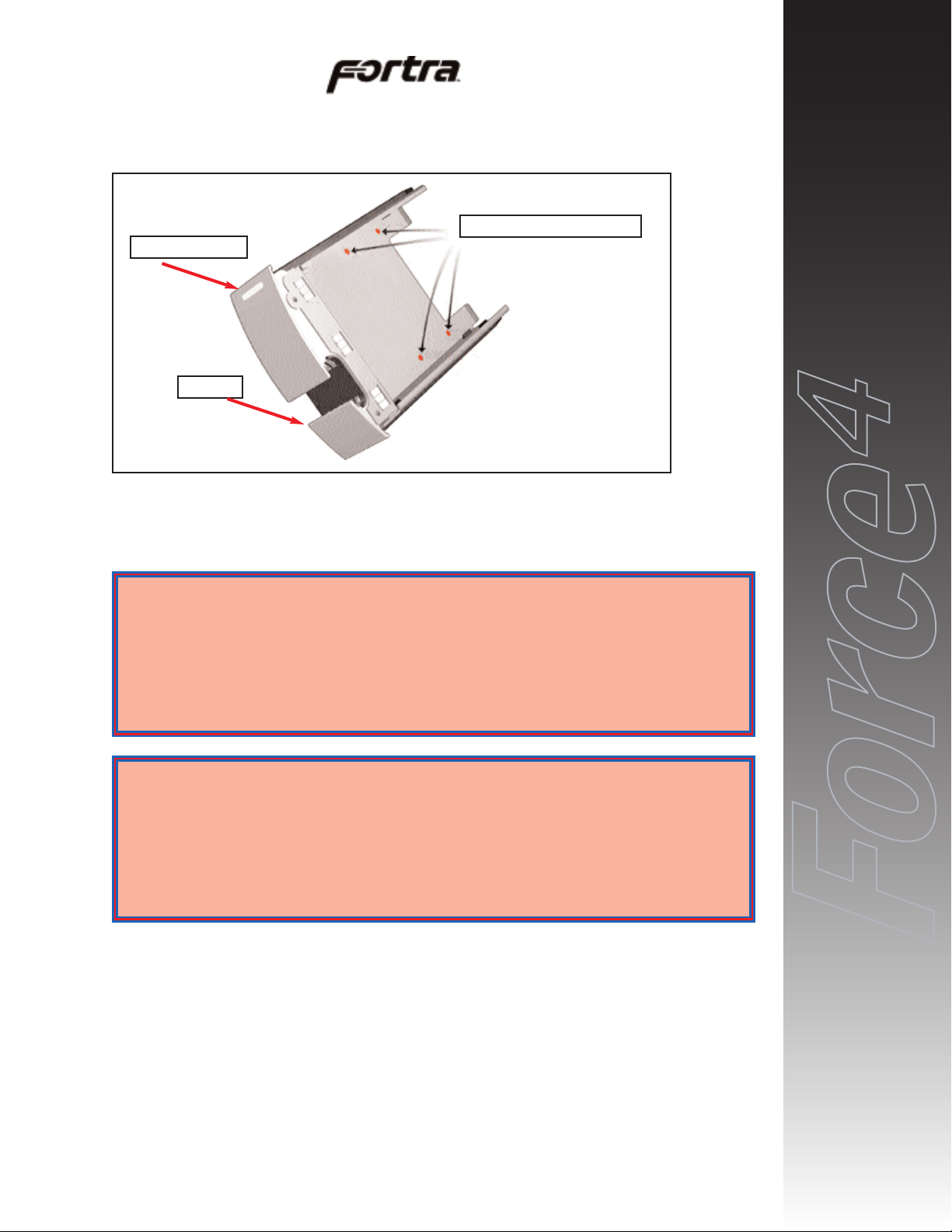
Drive Installation
Device mounting screws are included with the unit for device mounting. The
JMR part number for the #6-32" mounting screws is HDS-01906.
1. After removing the canister, place it on a static free surface along with the
device to be installed.
2. Place the device in the canister and mount it using the provided screws
(use 4 screws to mount the drive).
3. Replace the canister into the unit by following the steps for Removal of a
Device Canister but in reverse order.
FORTRAForce4G6 Installation Guide Rev B
3-2
Device Mounting Holes (4)
Status Indicators
Handle
WARNING: Before device installation, alleviate any electro-static discharge by
touching a grounded metal assembly. Static can be potentially damaging
to enclosure components.
WARNUNG: Berühren Sie vor der Festplatteninstallation geerdete
Metallgegenstände, um elektro statische Aufladung abzuleiten. Statische
Aufladung kann elektronische Gehäusekomponenten schwer beschädigen.
WARNING: The #6-32 mounting screws that are provided have been specially
designed to fit the canisters. Do not install the device using any other
screws than the ones provided.
WARNUNG: Die mitgelieferten Befestigungsschrauben #6-32 wurden speziell
für die Einschübe angefertigt und zur Befestigung der Festplatte sollten
Sie keinesfalls andere als diese verwenden.

4. Repeat steps 1 through 3 until all devices are installed.
5. Configure ID, and other options as required (see Chapter 4
).
6. Establish host connection (see Chapter 4
).
FORTRAForce4G6 Installation Guide Rev B
3-3
This chapter covers the Fibre Channel setup for the FORTRA
FFoorrccee
44
G6
system.
This figure shows the slot numbering sequence used to refer to device canisters
and also shows the default ID value for each slot.
FORTRAForce4G6 Installation Guide Rev B
4-1
WARNING: Take care when connecting the unit to an AC power source to
ensure that it is plugged-in to a circuit of the appropriate rating (110v or
220v). For safe operation, the circuit should have over-current protection
to prevent damage to the unit in the event of circuit overloading.
WARNUNG: Vergewissern Sie sich, daß die Netzspannung (220V / 110V)
korrekt eingestellt ist, bevor Sie das Gerät mit dem Stromnetz verbinden.
Zur Sicherheit sollte das Netz über einen Überspannungsschutz zur
Vermeidung von Schäden im Falle einer Überlast verfügen.
WARNING: When connecting the unit to an AC outlet or power strip, ensure
that the outlet has the proper connection for grounding. The AC power
cables included with the unit have three prongs, one of which is used for
the ground connection. Do not use a two prong AC cable with the unit
since this will not allow for proper unit grounding and could cause
problems with normal unit operation.
WARNUNG: Bei der Verbindung der Unit mit einer Steckdose oder einer
Verteilerdose sollten sie auf eine korrekte Erdung derselben achten. Die
mitgelieferten Kaltgeräteanschlußkabel habe 3 Kontakte, von denen
einer zur Erdung verwendet wird. Verwenden Sie kein Stromkabel mit 2
Anschlüssen, da dieses keine korrekte Erdung ermöglicht und Probleme
während des regulären Betriebs verursachen kann.
4. Fibre Channel Setup
Slot 0, ID 0
Slot 1, ID 1
Slot 2, ID 2
Slot 3, ID 3
Slot 4, ID 4
Slot 5, ID 5
Power Supply
Canister Lock

Default Slot ID
Drive Bay Default ID/Jumper
Slot 0 (top) ID 0 / W1
Slot 1 ID 1 / W2
Slot 2 ID 2 / W3
Slot 3 ID 3 / W4
Slot 4 ID 4 / W6
Slot 5 ID 5 / W7
Setting Slot ID
The ID for each slot can be set using jumpers located on the backplane of the unit.
To access the jumpers the blower must be removed. To remove the blower refer
to Chapter 5
.
The following tables show the jumper settings for Fibre ID’s 0-127.
FORTRAForce4G6 Installation Guide Rev B
4-2
Jumper 6
Jumper 5
Jumper 4
Jumper 3
Jumper 2
Jumper 1
Jumper 0
W1 - Slot 0 ID
Jumpers
W2 - Slot 1 ID
Jumpers
W3 - Slot 2 ID
Jumpers
W4- Slot 3 ID
Jumpers
W6 - Slot 4 ID
Jumpers
W7 - Slot 5 ID
Jumpers
NOTE: W1 sits above
W2 behind a metal
plate. W1 can not be
seen in this photo.

FORTRAForce4G6 Installation Guide Rev B
4-3
FibreIDJmp0 Jmp1Jmp2Jmp3Jmp4Jmp5Jmp
6
0 C C C C C C C
1 O C C C C C C
2 C O C C C C C
3 O O C C C C C
4 C C O C C C C
5 O C O C C C C
6 C O O C C C C
7 O O O C C C C
8 C C C O C C C
9 O C C O C C C
10 C 0 C O C C C
11 O 0 C O C C C
12 C C O O C C C
13 O C O O C C C
14 C 0 O O C C C
15 O 0 O O C C C
16 C C C C O C C
17 O C C C O C C
18 C O C C O C C
19 O O C C O C C
20 C C O C O C C
21 O C O C O C C
22 C O O C O C C
23 O O O C O C C
24 C C C O O C C
25 O C C O O C C
26 C O C O O C C
27 O O C O O C C
28 C C O O O C C
29 O C O O O C C
30 C O O O O C C
31 O O O O O C C
32 C C C C C 0 C
33 O C C C C 0 C
34 C O C C C 0 C
35 O O C C C 0 C
36 C C O C C 0 C
37 O C O C C 0 C
38 C O O C C 0 C
39 O O O C C 0 C
40 C C C O C O C
41 O C C O C O C
42 C O C O C O C
43 O O C O C O C
44 C C O O C O C
45 O C O O C O C
46 C O O O C O C
47 O O O O C O C
48 C C C C O O C
49 O C C C O O C
FibreIDJmp0 Jmp1Jmp2Jmp3Jmp4Jmp5Jmp
6
50 C O C C O O C
51 O O C C O O C
52 C C O C O O C
53 O C O C O O C
54 C O O C O O C
55 O O O C O O C
56 C C C O O O C
57 O C C O O O C
58 C O C O O O C
59 O O C O O O C
60 C C O O O O C
61 O C O O O O C
62 C O O O O O C
63 O O O O O O C
64 C C C C C C O
65 O C C C C C O
66 C O C C C C O
67 O O C C C C O
68 C C O C C C O
69 O C O C C C O
70 C O O C C C O
71 O O O C C C O
72 C C C O C C O
73 O C C O C C O
74 C O C O C C O
75 O O C O C C O
76 C C O O C C O
77 O C O O C C O
78 C O O O C C O
79 O O O O C C O
80 C C C C O C O
81 O C C C O C O
82 C O C C O C O
83 O O C C O C O
84 C C O C O C O
85 O C O C O C O
86 C O O C O C O
87 O O O C O C O
88 CO C C O O C O
89 CO C C O O C O
90 CO O C O O C O
91 CO O C O O C O
92 C C O O O C O
93 O C O O O C O
94 C O O O O C O
95 O O O O O C O
96 C C C C C 0 O
97 O C C C C 0 O
98 C O C C C 0 O
99 O O C C C 0 O

Legend: O = Open (no jumper) C = Closed (jumper on)
Option Settings
Additional drive option jumpers for remote and delayed start are located on the
unit I/O board. They must be set at the factory.
Remote Start
This feature is disabled by default and can be enabled for OEM use.
Delayed Start
This feature is disabled by default and can be enabled for OEM use.
Rear I/O Connections
The rear of the unit and the I/O connections are described below.
FORTRAForce4G6 Installation Guide Rev B
4-4
FibreIDJmp0 Jmp1Jmp2Jmp3Jmp4Jmp5Jmp
6
100 C C O C C O O
101 O C O C C O O
102 C O O C C O O
103 O O O C C O O
104 C C C O C O O
105 O C C O C O O
106 C O C O C O O
107 O O C O C O O
108 C C O O C O O
109 O C O O C O O
110 C 0 O O C O O
111 O 0 O O C O O
112 C C C C O O O
113 O C C C O O O
114 C 0 C C O O O
115 O 0 C C O O O
116 C C O C O O O
117 O C O C O O O
118 C O O C O O O
119 O O O C O O O
120 C C C O O O O
121 O C C O O O O
122 C O C O O O O
123 O O C O O O O
124 C C O O O O O
125 O C O O O O O
126 C O O O O O O
127 O O O O O O O

CH-A 1
Loop A connection 1. This is a SFP fibre channel connector used to connect to a
host system or to an expansion chassis for Loop A.
CH-A 2
Loop A connection 2. This is a SFP fibre channel connector used to connect to a
host system or to an expansion chassis for Loop A.
CH-B 1
Loop B connection 1. This is a SFP fibre channel connector used to connect to a
host system or to an expansion chassis for Loop B.
CH-B 2
Loop B connection 2. This is a SFP fibre channel connector used to connect to a
host system or to an expansion chassis for Loop B.
System Fault Audible Alert
A system fault includes over temperature, power fault, or blower fault. The
buzzer will sound off with a sequence of beeps to indicate the fault that has
occurred.
2 beeps = Temperature Fault
3 beeps = Blower Fault;
5 beeps = Power Supply Fault.
Alarm Reset
This button will turn off the audible alert. Pressing this button will not reset
power to the unit, it will only silence the alarm.
FORTRAForce4G6 Installation Guide Rev B
4-5
CH B 2
CH B 1
Alarm Reset
Button
CH A 1 CH A 2
AC Input
Power
On/Off

FORTRAForce4G6 Installation Guide Rev B
5-1
This chapter covers operations of the blower for the FORTRA
FFoorrccee
44
G6 units.
Refer to Chapter 1 for blower specifications. The blower is easily removable.
Failure to replace a non-working blower within a reasonable period of time may
expose drives to extreme heat that could cause loss of data.
The blower is located on the back of the unit. If there is a blower fault, both of
the device canister status LEDs will blink ‘Red’ and an audible alert will sound.
Pressing the Alarm Reset button located on the back of the unit will turn off the
audible alert.
Blower Removal/Insertion
The blower is designed to be easily installed and removed.
1. Unfasten the blower thumbscrew by
turning counterclockwise. A Philips
head screwdriver can be used if the
thumbscrew is too tight to turn by
hand.
2. Remove the blower canister by pulling out
on the thumbscrews and lifting it out of
the bottom two slots.
WARNING: Blowers are a system critical component. Non-operating blowers
should be replaced as soon as possible to avoid data loss or device failure.
WARNUNG: Gebläse sind für die Funktion wichtige Komponenten. Nicht
funktionierende Gebläse sollten so schnell wie möglich ersetzt werden,
um Datenverluste oder Fehlfunktionen zu vermeiden.
WARNING: Because the blower continues to spin for a short while, the unit
should be turned off at least 10 seconds before replacing the fan to
prevent injury.
WARNUNG: Um Verletzungen zu vermeiden, sollte das Gerät wenigstens 10
Sekunden vor Entnahme der Gebläse ausgeschaltet werden, da die
Flügelräder der Gebläse nachlaufen.
5. Blower Operation

3. Unplug the blower from the backplane. The connector
is keyed so that it can be reinstalled correctly and has
also been placed through a holder on the fan bracket to
keep it out of the way during fan installation and
removal.
Reverse the steps to reinstall the blower.
The following figure shows the blower intake access hole.
Contact with the access hole must be avoided while the blower
is running to prevent injury.
Blower Replacement
If the blower has stopped running or the front device canister status LEDs are all
blinking ‘Red’, the blower may need to be replaced.
Before replacing, the cable connection should be checked to ensure that the
connector is firmly seated and that there is nothing blocking the blower intake
blades that could cause interference. If you believe a blower is in a nonfunctional
state, please contact the place of purchase for repair or replacement.
The JMR part numbers for a replacement blower is shown in the table below.
Replacement parts include the canister with the fan.
Model JMR Part Number
4-bay FAD-00014
FORTRAForce4G6 Installation Guide Rev B
5-2
WARNING: Avoid direct contact with the blower intake access hole while the
blower is running. The blower operates at high speeds and can cause
injury.
WARNING: Blowers are a system critical component. Non-operating blowers
should be replaced as soon as possible to avoid data loss or device failure.
WARNUNG: Gebläse sind für die Funktion wichtige Komponenten. Nicht
funktionierende Gebläse sollten so schnell wie möglich ersetzt werden,
um Datenverluste oder Fehlfunktionen zu vermeiden.

This chapter covers the operations of the power supply for FORTRA
FFoorrccee
44
G6 units. For operation, the AC cord (included) must be connected to the AC
Inlet at the back of the unit, and the On/Off switch must be switched ON. The
Status LED on the power supply will light to indicate the power supply is
functioning properly. If the power supply experiences a problem and cannot
operate within its normal specifications, the Status LED will light ‘Red’ and an
audible alert will sound. Pressing the Alarm Reset button located on the back of
the unit will turn off the audible alert.
Power Supply Removal/Insertion
Follow the following steps to remove a power supply in a 4-bay unit.
1. Unlock the unit (see Chapter 3 for Device
Installation instructions) & open the handle
by pulling out. This action will disconnect
the supply canister from the unit.
2. Grab the handle and pull straight out.
3. Carefully remove the supply from the unit. It is ok to grab the sides of
the supply to fully remove it.
Reverse the steps to reinstall the power supply.
FORTRAForce4G6 Installation Guide Rev B
6-1
Handle
Status LED
The Identification
symbol warns the
user that the
canister houses
an electrical
device that should
not be tampered
with.
6. Power Supply Operation

Power Supply Replacement
If the Power supply Status LED indicator is ‘Red’, the power supply may need to
be replaced. The unit should be reset (turned on & off), and the power supply
should be removed and then reinstalled. The AC cable connection in the back of
the unit should be checked to ensure that the plug is firmly seated in the power
supply. If the Status LED indicator is still ‘Red’, then the power supply should
be replaced.
If the power supply fan is not functioning but the power supply still works, the
power supply should be replaced as soon as possible. Leaving the power supply
running without the fan could cause the power supply to overheat and shutdown
at any time and may cause damage to the supply and other installed devices.
If you believe a power supply is in a nonfunctional state, please contact the place
of purchase for repair or replacement.
The JMR part number for a replacement power supply is shown in the following
table. Replacement parts include the canister with the power supply.
Model JMR Part Number Color
4-bay DSSH-085 Silver
4-bay DSSH-085-02 Black
FORTRAForce4G6 Installation Guide Rev B
6-2

This chapter covers the installation of the Intel PCI RAID Controller that is
shipped with the FORTRA
Force4 G6 RAID System. The model number of
the PCI RAID Controller is ICP Vortex number GDT8122RZ (ICP Vortex is a
wholly owned subsidiary of Intel Corporation)
Installing the PCI Controller
To install the PCI Controller, perform the following steps:
1) Switch off the PCI computer and disconnect all cables. Ensure that
the power cord is removed first.
2) Following the instructions in the computer manual, open the case of
the PCI computer, so that you have easy access to the PCI expansion
slots.
3) Select a free 64 Bit PCI bus-master slot or 32 Bit PCI bus-master slot
and remove the metal bracket, following the instructions in your PCI
computer manual. It is essential that the ICP Controller is plugged
into a bus-master slot (it will NOT work in a slave or non-busmaster
slot).
4) Push the ICP Controller firmly into the correct PCI bus-master slot.
Make sure that the controller fits tightly into it, and that the external
connectors stick out of the computer case. Now, fix the ICP Controller
by tightening the screw of its bracket.
5) Reconnect the PCI computer systems covers, cables and lastly the
power cord.
6) Before powering up the PCI computer system, connect the Fibre
Channel cable/cables to the G6 sub-system. The cable to be used
should have a HSSDC connector at one end and a HSSDC2 connector
at the other end.
7) The PCI computer system is now ready to be powered up.
Configuring RAID Sets
To configure the RAID sets, refer to the ICP Vortex User Manual located on the
CD shipped with the FORTRAForce4G6 RAID System.
FORTRAForce4G6 Installation Guide Rev B
7-1
7. Installing the Intel
PCI RAID Controller

FORTRAForce4G6 Installation Guide Rev B
8-1
For current information on this product, including updates to the manual and
technical support related issues, please contact the sales support section of our
web page at www.jmr.com, or you can contact our Technical Support division
directly at the address below.
US Corporate Headquarters
JMR Electronics, Inc.
ATTN: Technical Support Division
20400 Plummer St.
Chatsworth, CA 91311
Customer Support: (818) 739-1140
E-mail: techsupport@jmr
.com
Office Hours: Monday-Friday 8:00 A.M. to 5:00 P.M., Pacific Standard Time
Internet: http://www
.jmr.com
Manual Changes
Revision A - Initial Release
Revision B - Changed from 4-bay G4 to 6-bay G6
8. Product Support

FORTRAForce4G6 Installation Guide Rev B
A-1
Drive Manufacturers
Fujitsu
Internet Address: www
.fcpa.com
Hitachi
Internet Address: www
.hitachi.com
IBM (International Business Machines Corporation)
Internet Address: www
.ibm.com
Maxtor
Internet Address: www
.maxtor.com
Seagate Technology
Internet Address: www
.seagate.com
RAID Controller Manufacturers
Adaptec, Inc.
Internet Address: www
.adaptec.com
Chaparral Network Storage
Internet Address: www
.chaparralnet.com
Digi-Data Corporation
Internet Address: www
.digidata.com
Infortrend Corporation
Internet Address: www
.infortrend.com
Intel ICP VORTEX (Intelligent Computer Peripherals)
Internet Address: www
.icp-vortex.com
Mylex Corporation
Internet Address: www
.mylex.com
Silicon Image, CMD Storage Systems
Internet Address: www
.cmd.com
Appendix A. Drive and Controller
Manufacturers

Host Bus Adapter Manufacturers
Adaptec, Inc.
Internet Address: www
.adaptec.com
Antares Microsystems
Internet Address: www
.antares.com
Emulex Corporation
Internet Address: www
.emulex.com
JNI Corporation
Internet Address: www
.jni.com
QLogic Corp.
Internet Address: www
.qlogic.com
FORTRAForce4G6 Installation Guide Rev B
A-2
 Loading...