

Page 1

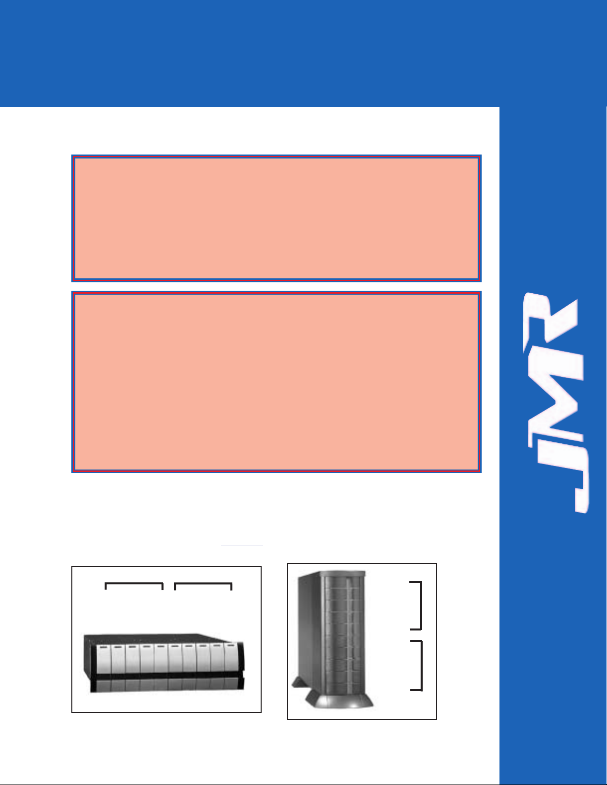
H1 Chaparral G5312
10-bay Rackmount & Tower Enclosures
Installation Guide
July 16, 2002 • Revision C
Patent Pending
Page 2

FORTRAH1 Chaparral G5312 Installation Guide Rev C
ii
Copyright
Copyright 2000, 2001 by JMR Electronics, Inc. All Rights Reserved. No part of this publication may be
reproduced, transmitted, transcribed, stored in a retrieval system, or translated into any language, in any form or
by any means, electronic, mechanical, photocopying, recording or otherwise, without the express written
permission of JMR Electronics, Inc.
Sales and Ordering Information
JMR Electronics, Inc.
20400 Plummer Street
Chatsworth, CA 91311 USA
Phone: 818-993-4801
Fax: 818-993-9173
Office Hours: Monday-Friday 8:00 A.M. to 5:00 P.M., Pacific Standard Time
European Corporate Headquarters
JMR Electronics United Kingdom
Iain Pickthall
P.O. Box 3058 Wokingham
Berkshire - RG40 3FU - United Kingdom
Phone: + 44-118-973-6018
Fax: + 44-118-973-7191
E-Mail: Iain@jmr.com
Internet: http://www.jmr.com
Trademarks
JMR, the JMR logo, and FORTRAare registered trademarks of JMR Electronics, Inc. All other product and
brand names are the property of their respective holders.
Changes
The material in this document is for information only and is subject to change without notice. JMR Electronics,
Inc. reserves the right to make changes to this manual and the equipment described herein without notice. JMR
has made all reasonable efforts to ensure that the information in this manual is accurate and complete. However,
JMR shall not be liable for any technical or editorial errors or omissions made herein or for incidental, special,
or consequential damage of whatsoever nature resulting from the furnishing of this manual, or operation and
performance of equipment with this manual.
Disclaimer
The original product packaging has been tested and is safe under normal shipping circumstances. Reshipping
the product without using the original product packaging will void the warranty. Do not ship the unit with
canisters or power supplies installed as this will void the warranty and could cause damage to the unit and drives.
The canisters should be packaged separately within the product packaging as provided.
FCC Information
The FORTRAequipment generates, uses and can radiate radio frequency energy. If the FORTRAArray is
not installed and used properly (that is, in strict compliance with these instructions), it may cause interference to
radio and television reception.
The FORTRAequipment and its contents are designed to comply with the limits for a Class A computing
device in accordance with the specifications in Part 15 of FCC rules. These rules are designed to provide
reasonable protection against radio interference in a commercial installation. However, there is no guarantee
that interference will not occur in a particular installation. Operation of this equipment in a residential area is
likely to cause interference, in which case the user, at his own expense, will be required to take whatever
measures are necessary to correct the interference.
Y ou may find the FCC booklet, How to Identify and Resolve Radio Interference Problems, helpful. This booklet
is available from the U.S. Government Printing Office, Washington, DC 20402. Stock #004-000-00345-4.
Printed in the USA
Part Number PUB-00180
Revision C, July, 2002 SCS
Patent Pending
WARNING: Changes or modifications, not expressly approved by the
manufacturer, could void the user's authority to use the equipment.
WARNUNG: Nicht ausdrücklich durch den Hersteller genehmigte Änderungen
oder Modifikationen können die Erlaubnis Zur benutzung der Produkte
gefährden.
Page 3

FORTRAH1 Chaparral G5312 Installation Guide Rev C
iii
Table of Contents
1. Introduction
2/4/6/8/10/12/15-Bay Product Family Features . . . . . . . . . . . . . . . . . . . . . .1-1
10-bay Rackmount Specifications . . . . . . . . . . . . . . . . . . . . . . . . . . . . . . . .1-2
10-bay Tower Specifications . . . . . . . . . . . . . . . . . . . . . . . . . . . . . . . . . . . .1-2
SCSI Features . . . . . . . . . . . . . . . . . . . . . . . . . . . . . . . . . . . . . . . . . . . . . . . .1-3
Tri Channel . . . . . . . . . . . . . . . . . . . . . . . . . . . . . . . . . . . . . . . . . . . . . . .1-3
Automatic Built-In Termination . . . . . . . . . . . . . . . . . . . . . . . . . . . . . . .1-3
ID Selection . . . . . . . . . . . . . . . . . . . . . . . . . . . . . . . . . . . . . . . . . . . . . .1-3
SAF-TE . . . . . . . . . . . . . . . . . . . . . . . . . . . . . . . . . . . . . . . . . . . . . . . . .1-3
2. Hardware Specification
Environmental Specifications . . . . . . . . . . . . . . . . . . . . . . . . . . . . . . . . . . . .2-2
Electrical Specifications . . . . . . . . . . . . . . . . . . . . . . . . . . . . . . . . . . . . . . . .2-2
Agency Compliance . . . . . . . . . . . . . . . . . . . . . . . . . . . . . . . . . . . . . . . . . . .2-2
Packaging Specifications . . . . . . . . . . . . . . . . . . . . . . . . . . . . . . . . . . . . . . .2-2
Disclaimer . . . . . . . . . . . . . . . . . . . . . . . . . . . . . . . . . . . . . . . . . . . . . . . .2-2
Thermal Specifications . . . . . . . . . . . . . . . . . . . . . . . . . . . . . . . . . . . . . . . . .2-3
Rotation Vibration Specifications . . . . . . . . . . . . . . . . . . . . . . . . . . . . . . . . .2-3
Fault Indication Features . . . . . . . . . . . . . . . . . . . . . . . . . . . . . . . . . . . . . . .2-3
Fault Indicators . . . . . . . . . . . . . . . . . . . . . . . . . . . . . . . . . . . . . . . . . . . .2-3
Audible Alert . . . . . . . . . . . . . . . . . . . . . . . . . . . . . . . . . . . . . . . . . . . . .2-3
SYS-FLT . . . . . . . . . . . . . . . . . . . . . . . . . . . . . . . . . . . . . . . . . . . . . . . . .2-3
S-ACT . . . . . . . . . . . . . . . . . . . . . . . . . . . . . . . . . . . . . . . . . . . . . . . . . . .2-3
3. Device Installation
SCA Connection and Hot-Swapping . . . . . . . . . . . . . . . . . . . . . . . . . . . . . .3-1
Canister Removal/Insertion . . . . . . . . . . . . . . . . . . . . . . . . . . . . . . . . . . . . .3-1
Drive Installation . . . . . . . . . . . . . . . . . . . . . . . . . . . . . . . . . . . . . . . . . . . . .3-2
4. SCSI Setup
Slot Settings . . . . . . . . . . . . . . . . . . . . . . . . . . . . . . . . . . . . . . . . . . . . . . . . .4-1
Available ID's . . . . . . . . . . . . . . . . . . . . . . . . . . . . . . . . . . . . . . . . . . . . .4-2
ID Conflict . . . . . . . . . . . . . . . . . . . . . . . . . . . . . . . . . . . . . . . . . . . . . . .4-2
Option Settings . . . . . . . . . . . . . . . . . . . . . . . . . . . . . . . . . . . . . . . . . . . . . .4-2
Delayed Start Option Jumper . . . . . . . . . . . . . . . . . . . . . . . . . . . . . . . . .4-2
Remote Start Option Jumper . . . . . . . . . . . . . . . . . . . . . . . . . . . . . . . . .4-2
TTaabbllee ooff
CCoonntteennttss
Page 4

Front Status LEDs . . . . . . . . . . . . . . . . . . . . . . . . . . . . . . . . . . . . . . . . . . . . .4-3
External I/O Connection . . . . . . . . . . . . . . . . . . . . . . . . . . . . . . . . . . . . . . . .4-3
Connections & LEDs . . . . . . . . . . . . . . . . . . . . . . . . . . . . . . . . . . . . . . . . . .4-3
Host Out . . . . . . . . . . . . . . . . . . . . . . . . . . . . . . . . . . . . . . . . . . . . . . . . .4-3
Host In . . . . . . . . . . . . . . . . . . . . . . . . . . . . . . . . . . . . . . . . . . . . . . . . . . .4-3
Channel A Out . . . . . . . . . . . . . . . . . . . . . . . . . . . . . . . . . . . . . . . . . . . .4-4
Channel B Out . . . . . . . . . . . . . . . . . . . . . . . . . . . . . . . . . . . . . . . . . . . .4-4
RS232 . . . . . . . . . . . . . . . . . . . . . . . . . . . . . . . . . . . . . . . . . . . . . . . . . . .4-4
S-ACT . . . . . . . . . . . . . . . . . . . . . . . . . . . . . . . . . . . . . . . . . . . . . . . . . . .4-4
G5312 SCSI Connections . . . . . . . . . . . . . . . . . . . . . . . . . . . . . . . . . . . . . .4-4
G5312 Operating Mode . . . . . . . . . . . . . . . . . . . . . . . . . . . . . . . . . . . . . . . .4-4
5. Blower Operation
Blower Removal/Insertion . . . . . . . . . . . . . . . . . . . . . . . . . . . . . . . . . . . . . .5-1
Blower Replacement . . . . . . . . . . . . . . . . . . . . . . . . . . . . . . . . . . . . . . . . . . .5-2
6. Power Supply Operation
Power Supply Removal/Insertion . . . . . . . . . . . . . . . . . . . . . . . . . . . . . . . . .6-1
Low Power Mode (Standby Power) . . . . . . . . . . . . . . . . . . . . . . . . . . . . . . .6-2
Power Supply Replacement . . . . . . . . . . . . . . . . . . . . . . . . . . . . . . . . . . . . .6-2
7. FR10 Cabinet Installation
Rail Mounting Kit Hardware . . . . . . . . . . . . . . . . . . . . . . . . . . . . . . . . . . . .7-2
Spare Hardware Parts . . . . . . . . . . . . . . . . . . . . . . . . . . . . . . . . . . . . . . . . . .7-2
Rail Installation . . . . . . . . . . . . . . . . . . . . . . . . . . . . . . . . . . . . . . . . . . . . . . .7-2
8. Installing the G5312
Installation Steps . . . . . . . . . . . . . . . . . . . . . . . . . . . . . . . . . . . . . . . . . . . . . .8-1
ID Settings & Option Jumpers . . . . . . . . . . . . . . . . . . . . . . . . . . . . . . . . . . .8-2
Controller Canister Installation . . . . . . . . . . . . . . . . . . . . . . . . . . . . . . . . . . .8-2
9. SAF-TE Operation
SAF-TE ID . . . . . . . . . . . . . . . . . . . . . . . . . . . . . . . . . . . . . . . . . . . . . . . . . .9-1
Minimum System Requirements . . . . . . . . . . . . . . . . . . . . . . . . . . . . . . . . .9-1
Software Installation . . . . . . . . . . . . . . . . . . . . . . . . . . . . . . . . . . . . . . . . . . .9-1
DOS Installation . . . . . . . . . . . . . . . . . . . . . . . . . . . . . . . . . . . . . . . . . . .9-2
Windows 95 & 98 Installation . . . . . . . . . . . . . . . . . . . . . . . . . . . . . . . .9-2
Software Walkthrough . . . . . . . . . . . . . . . . . . . . . . . . . . . . . . . . . . . . . . . . .9-2
Software Controls . . . . . . . . . . . . . . . . . . . . . . . . . . . . . . . . . . . . . . . . . .9-2
FORTRAH1 Chaparral G5312 Installation Guide Rev C
iv
Page 5

Part 1 Basic Software Overview . . . . . . . . . . . . . . . . . . . . . . . . . . . . .9-2
Part 2 FORTRAÒ SAF-TE Commands . . . . . . . . . . . . . . . . . . . . . . . .9-5
Command Overview . . . . . . . . . . . . . . . . . . . . . . . . . . . . . . . . . . . . . . . .9-6
Updating Firmware . . . . . . . . . . . . . . . . . . . . . . . . . . . . . . . . . . . . . . . . . . . .9-11
EETBL.ASM Default Settings File . . . . . . . . . . . . . . . . . . . . . . . . . . . .9-12
Important Settings . . . . . . . . . . . . . . . . . . . . . . . . . . . . . . . . . . . . . . . . . .9-13
SAF-TE Commands . . . . . . . . . . . . . . . . . . . . . . . . . . . . . . . . . . . . . . . . . . .9-13
Perform Slot Operation Command . . . . . . . . . . . . . . . . . . . . . . . . . . . . .9-14
Read Device Slot Status Command . . . . . . . . . . . . . . . . . . . . . . . . . . . .9-14
Read Enclosure Configuration Command . . . . . . . . . . . . . . . . . . . . . . .9-15
Read Enclosure Status Command . . . . . . . . . . . . . . . . . . . . . . . . . . . . . .9-15
Send Global Command . . . . . . . . . . . . . . . . . . . . . . . . . . . . . . . . . . . . . .9-16
Write Device Slot Status Command . . . . . . . . . . . . . . . . . . . . . . . . . . . .9-16
Optional SAF-TE Commands . . . . . . . . . . . . . . . . . . . . . . . . . . . . . . . . . . . .9-17
*Activate Power Supply Command . . . . . . . . . . . . . . . . . . . . . . . . . . . .9-17
*Read Device Insertions Command . . . . . . . . . . . . . . . . . . . . . . . . . . . .9-17
*Read Usage Statistics Command . . . . . . . . . . . . . . . . . . . . . . . . . . . . .9-17
*Set SCSI ID Command . . . . . . . . . . . . . . . . . . . . . . . . . . . . . . . . . . . . .9-17
*Set Fan Speed Command . . . . . . . . . . . . . . . . . . . . . . . . . . . . . . . . . . .9-17
10. Product Support
US Corporate Headquarters . . . . . . . . . . . . . . . . . . . . . . . . . . . . . . . . . . . . .10-1
Manual Changes . . . . . . . . . . . . . . . . . . . . . . . . . . . . . . . . . . . . . . . . . . . . . .10-1
Appendix A. Drive and Controller Manufacturers
Drive Manufacturers . . . . . . . . . . . . . . . . . . . . . . . . . . . . . . . . . . . . . . . . . . .A-1
RAID Controller Manufacturers . . . . . . . . . . . . . . . . . . . . . . . . . . . . . . . . . .A-1
Host Bus Adapter Manufacturers . . . . . . . . . . . . . . . . . . . . . . . . . . . . . . . . .A-2
FORTRAH1 Chaparral G5312 Installation Guide Rev C
v
Page 6

FORTRAH1 Chaparral G5312 Installation Guide Rev C
1-1
The 10-bay FORTRAH1 Chaparral G5312 is designed to be used with a host
system to provide a high-end RAID storage solution. The following is a summary
of the H1 Chaparral G5312 Tower and Rackmount enclosure features:
• The 10-bay FORTRA
H1 Chaparral G5312 Tower enclosure supports
up to ten 3.5" HH or LP SCA 80-pin drives. It supports single-ended, and
Ultra2 (LVD) SCSI buses. This model has three SCSI channels and builtin auto-switching SE/LVD multi-mode termination on each channel. This
SCSI RAID Tower enclosure houses one G5312 RAID controller.
• The 10-bay FORTRA
H1 Chaparral G5312 Rackmount is a 19" wide,
3U (5-1/4") high rackmount enclosure that supports up to ten 3.5" HH or
LP SCA 80-pin drives. All other features are the same as the 10-bay
FORTRA
H1 Chaparral G5312 Tower.
22//44//66//88//1100//1122//1155--BBaayy
Product Family Features
FORTRAand StorBladeTMare families of high-end enclosures designed for
high-volume performance RAID storage solutions. The following table shows the
features of the FORTRA
2/4/6/8/10/12/15-bay and StorBladeTMproducts:
1. Introduction
2-bay
4-bay
1,3
6-bay
*1,3
8-bay110-bay
*1,2
12-bay
15-bay
*1,3
StorBlade
Number of Device Bays 2 4 6 8 10 12 15 4
Number of Blowers 1 1 1 or 2 2 2 2 2 2
Number of Power Supplies 1 1 1 or 2 2 2 2 2 1 or 2
Number of I/O Channels (SCSI Only) 1 1 2 2 2 2 2
SCSI SE/LVD Supported
2 2 2 2 2 2 2
Fibre Channel Supported
2 2 2 2 2 2
Hot-Swap Canisters
2 2 2 2 2 2 2 2
Removable Power Supplies
2 2 2 2 2 2 2
Fibre only
Removable Blowers
2 2 2 2 2 2 2
Fibre Only
N+1 Power Supplies
2 2 2 2 2
Fibre only
N+1 Blowers
2 2 2 2 2 2
MIA Support (FC Only)
2 2 2 2
Loop Expansion Support (FC Only)
2 2 2 2 2 2
Daisy Chainable (SCSI Only)
2 2 2 2 2 2
Built-in Termination (SCSI Only)
2 2 2 2
Auto Termination (SCSI Only)
2 2 2 2
SAF-TE/SES Ready (Optional)
2 2 2 2
Fibre only
SAF-TE/SES Compatible
2 2 2 2
Fibre only
SCSI to SCSI RAID Support
2 2 2 2
Fibre to SCSI RAID Support
2 2
Fibre to Fibre RAID Support
2 2 2
Fibre to ATA RAID Support
2
SCSI to ATA RAID Support
2
(D)esktop/(T)ower/(R)ackmount D D DTR T TR R TR R
* 6/10/15-bay unit features apply to both Tower and Rackmount models
1 Features are based on a standard configuration with no internal host controller(s) installed
2 Fibre channel 10/15-bay enclosures have built-in SES
3 Fibre Channel 2Gb Model available. 2Gb models use SFP transceivers.
Page 7

FORTRAproducts use advanced mid-plane technology developed by JMR,
which allows power supplies, drives, and all other enclosure components to
interface into a single board. This provides superior performance and easy
connectivity.
The host interface supports one SCSI-2 host connection and two SCSI-2 disk
connections. The SCSI-2 connections are made using a High-Density 68-pin
SCSI cable.
10-bay Rackmount Specifications
Dimensions/Weight
Unit Weight 40 lbs. (18.2kg)
Height 5-1/4" (3U) (133mm)
Width 19" (483mm)
Depth 23" (584mm)
Power Supply (Each power supply includes internal cooling fan)
Quantity: 2
Power: 430 Watts each (N+1) Power Factor Correction
Input: 100-260 VAC; 50-60Hz
Output: +5V @ 35A
+12V @ 30A
Blower
Quantity: 2
Size: 97mm (3.82") each
Air Flow: 25.42CFM (0.72m3/min)
Noise: 52dB(A)
10-bay Tower Specifications
Dimensions/Weight
Unit Weight 43 lbs. (19.5kg)
Height 20-1/2" (521mm)
Width 9-5/8" (235mm)
Depth 24" (610mm)
FORTRAH1 Chaparral G5312 Installation Guide Rev C
1-2
NOTE:
FORTRA
10-bay SCSI RAID enclosures do not support high-voltage
differential (HVD) SCSI
Page 8

Power Supply (Each power supply includes internal cooling fan)
Quantity: 2
Power: 430 Watts each (N+1) Power Factor Correction
Input: 100-260 VAC; 50-60Hz
Output: +5V @ 35A
+12V @ 30A
Blower
Quantity: 2
Size: 97mm (3.82") each
Air Flow: 25.42CFM (0.72m3/min) each
Noise: 52dB(A)
SCSI Features
Tri Channel
The 10-bay SCSI RAID with G5312 both Tower and Rackmount enclosures have
a tri SCSI bus configuration with five drive bays on internal bus A and five drive
bays on internal bus B. In addition, there are two external connections for SCSI
host bus connection IN and OUT.
Automatic Built-In Termination
The unit provides automatic dual-mode SE/LVD termination enable and disable
for any Single-Ended or LVD SCSI devices installed in the unit.
ID Selection
Standard default ID's are pre-configured as follows:
Channel A: ID 0, 1, 2, 3, 4
Channel B: ID 0, 1, 2, 3, 4
SAF-TE: Channel A, ID 5 (Optional)
SAF-TE
The SAF-TE command set is supported by the SAF-TE board installed in the unit.
Host setup software is included and is supported under Dos 5.0+, Windows 95,
and Windows 98. Boot disk must load DOS SCSI drivers from autoexec.bat and
config.sys. Host bus adapter ASPI drivers are required to run the test software.
The software is not needed for SAF-TE to operate. The processor will operate
normally without user intervention as long as the host bus adapter or RAID
controller supports the SAF-TE protocol.
FORTRAH1 Chaparral G5312 Installation Guide Rev C
1-3
Page 9
FORTRAH1 Chaparral G5312 Installation Guide Rev C
2-1
This chapter covers specification information for all FORTRAenclosures. The
following matrix describes the available configurations for FORTRA
and
StorBlade
TM
enclosures.
2. Hardware Specification
FR XX X L 2
1 X 2
X XX X X
SINGLE/DUAL CONTROLLER
S = Single Controller
D = Dual Controller
BACKPLANE TYPE
- = 1 Gigabit Backplane
2 = 2 Gigabit Backplane
CONTROLLER MANUFACTURER/MODEL#/INTERFACE
- = None (Blank if at the end of P/N)
H1 = Chaparral G5312/LVD Host/LVD Drives
H2 = Chaparral G7313/Fibre Host/LVD Drives
H3 = Chaparral K5312/LVD Host/LVD Drives
H4 = Chaparral K7313/Fibre Host/LVD Drives
H5 = Chaparral JSS122/LVD Host/LVD Drives
H6 = Chaparral JFS124/Fibre Host/LVDDrives
H8 = Chaparral JFS224/Fibre Host/LVD Drives
FZ = Microtest FileZerver Network Attached/Ethernet/LVD Drives
I2 = Infortrend Sentinel 2500-50/LVD Host/LVD Drives
Infortrend Sentinel 2500-50 w/IFT9282F/Fibre Host/LVD Drives
I3 = Infortrend EonRAID 2500-50 w/IFT9288B6B/Fibre Host/LVD Drives
I4 = Infortrend EonRAID 5251F/2G Fibre Host/2G Fibre Drives
I5 = Infortrend SentinelRAID 150/LVDHost/LVD Drives
IS = Infortrend EonRAID 7250-12U3D SCSI Host/ATA Drives
IF = Infortrend EonRAID 7250-12F2D Fibre Host/ATA Drives
M3 = Mylex DAC-FFx/1G Fibre Host/1G Fibre Drives
M5 = Mylex DAC-FFx2/2G Fibre Host/2G Fibre Drives
SAF-TE/SES
- = None (Blank if at the end of P/N)
S = SAF-TE/SES
POWER SUPPLY QUANTITY
# = A number Equal to Power Supplies in Enclosure
AC or DC POWER SUPPLY
- = AC Power Supply
D = DC Power Supply
COLOR - CANISTER/ACCENT
1 = Silver/Opal
2 = Black/Black
3 = Silver/Black
4 = Blue/Blue
DRIVE I/O SCSI CHANNELS or FIBRE LOOPS
# = A Number Equal to Drive I/O Channels
ENCLOSURE I/O
L = SCSI 3 Ultra 160 (LVD/SE Multimode, Fast-Wide, HD68)
F = 1 or 2Gb/s Fibre Channel
A = ATA
FIBRE GBIC READY
- = No GBIC Slots
G = GBIC Ready
NUMBER OF DRIVES
# = Drives (02,04,06,08,10,12,15)
FAMILY SERIES
FR = Fortra Rackmount
FT = Fortra Tower
1U = StorBlade Rackmount
u.s. Power cords Included
For International Models
Add Power Cord:
Australia = CBL-00602
Europe = CBL- 00525
UK = CBL-00677
Page 10
Environmental Specifications
Operating Temperature: 5°C to 40°C (41°F to 104°F)
Storage Temperature: 0°C to 65°C (32°F to 149°F)
The maximum recommended ambient temperature depends on the
recommendation of the manufacturer for the devices being installed.
Electrical Specifications
AC Inlet Type: IEC320/EN60320
Power Cord: NEMA5-15P
Power Supply: Auto-switching for 110/220V operation
Agency Compliance
FORTRAenclosures have been designed and built to comply with the FCC
Class A, UL, CSA/TUV, CE, and C-Tick standards. For more information on FCC
Class A compliances, see page 2.
Packaging Specifications
FORTRApackaging has been designed to be reusable and recyclable. Drives
may be installed and shipped in the canisters as long as the canisters are not
installed in the enclosure. Shipping the unit with canisters and/or power supplies
installed in the enclosure may cause damage to the enclosure or to the drives and
will void the warranty.
Packaging complies with ISTA (International Safe Transit Association) standards
and has been ISTA certified.
Each canister is pre-packaged in an anti-static bag. Do not throw the packaging
away if the product is intended for re-shipping. When transporting or shipping a
JMR approved shipping container must be used.
Disclaimer
The original product packaging has been tested and is safe under normal shipping
circumstances. Reshipping the product without using the original product
packaging will void the warranty. Do not ship the unit with canisters and/or
power supplies installed in the enclosure as this will void the warranty and could
cause damage to the unit and drives. The canisters should be packaged separately
within the product packaging, as provided.
FORTRAH1 Chaparral G5312 Installation Guide Rev C
2-2
SAFETY TIP: Reshipping the enclosure with canisters, drives, or power
supplies installed in the enclosure may cause damage to these
components and will void the warranty
SICHERHEITSHINWEIS: Der Versand des Gehäuses mit eingebauten
Einschüben, Platten und Netzteilen kann zur Beschädigung dieser
Komponenten führen und somit den Garantieanspruch gefährden.
Page 11

Thermal Specifications
FORTRAenclosures have been designed to meet the air-flow/cooling
requirements for popular 7,200, 10,000, and 15,000 RPM disk drives. Using high
performance blowers, air is pulled in from all open vents and exhausted out the
back of the unit.
On 10-bay units, the blower speed can be manually changed through the SAF-TE
interface for noise control.
Rotation Vibration Specifications
FORTRAenclosures have been designed to meet the rotation vibration/shock
requirements for popular 7,200, 10,000, and 15,000 RPM disk drives.
Fault Indication Features
This section reviews the indicators that will notify the user of a power supply or
blower that is in a fault state. More information is available in Chapter 5
(blowers) and Chapter 6 (power supply).
Fault Indicators
On a blower fault, all the front status LEDs will blink 'Red'. The blower LED on
the back of the unit will light red and an audible alert will sound.three times.
On a power supply fault, all the front status LEDs will also blink 'Red'. The
power supply fault LED will light and an audible alert will sound five times.
On a temperature fault, the audible alert will sound two times.
Audible Alert
There are three audible enclosure alerts:
Two beeps indicate a temperature issue.
Three beeps indicate a blower failure;
Five beeps indicate a power supply failure;
SYS-FLT
The SYS-FLT LED on the back of the unit indicates an error on the SAF-TE bus.
It will also blink whenever the host controller interrogates the SAF-TE processor
for a status update.
S-ACT
The S-ACT LED will blink to indicate activity on the SAF-TE bus.
FORTRAH1 Chaparral G5312 Installation Guide Rev C
2-3
Page 12
FORTRAH1 Chaparral G5312 Installation Guide Rev C
3-1
This chapter covers SCSI device installation for 10-bay rackmount and 10-bay
tower enclosures.
SCA Connection and Hot-Swapping
The unit uses SCA-2 (80-pin) connectors which provide a safe means of
connection/disconnection when hot-swapping devices. In order to hot-swap
devices, the host adapter or RAID controller and host operating software must
support the feature. Any SCA (80-pin) drive is capable of plugging directly into
the backplane of the unit and should not require any additional cabling or
connections.
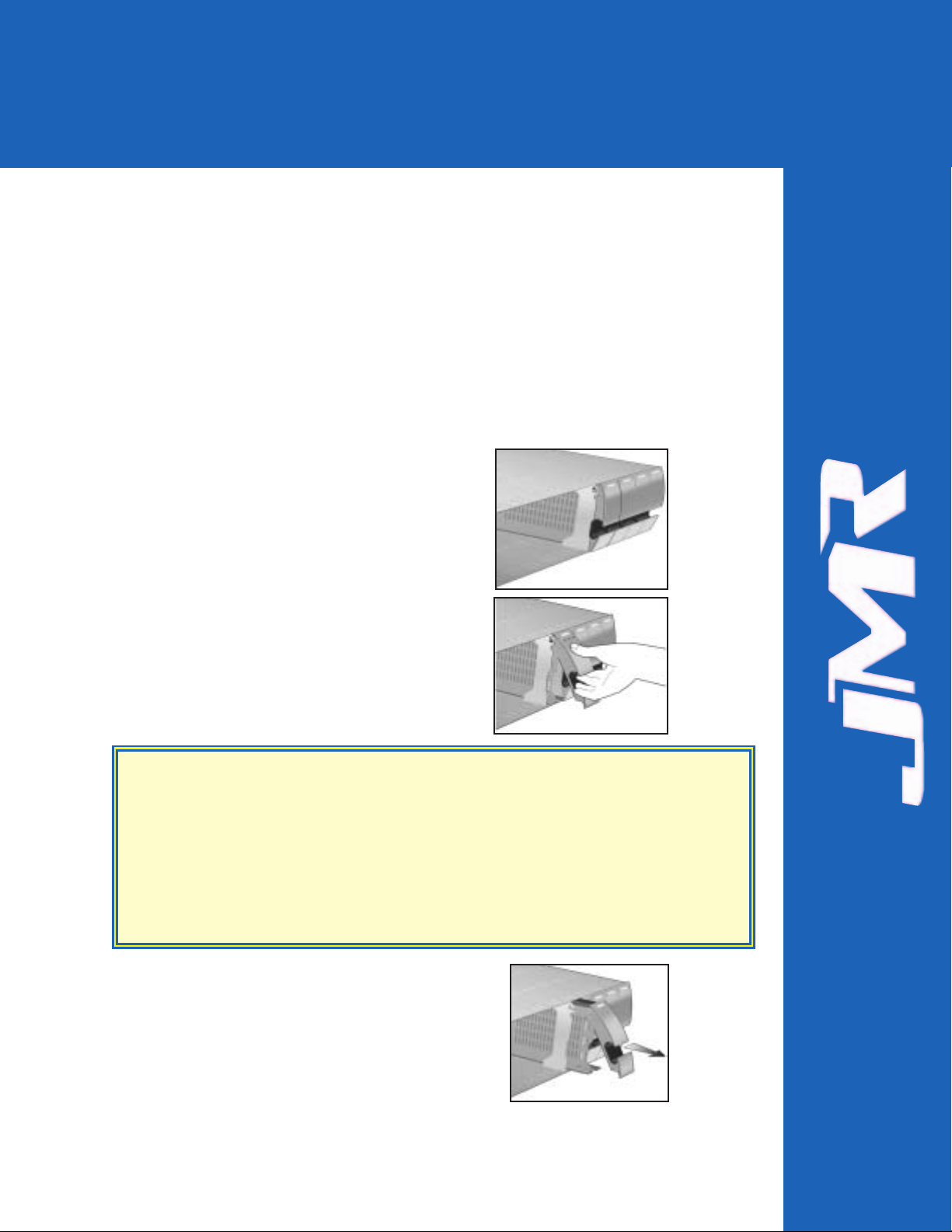
Canister Removal/Insertion
1. The photo to the right shows the canister in a
locked position.
2. Pull the handle out to unlock the canister
from the FORTRA
unit. Ensure that the
thumb is placed below the line. Pressing the
thumb against the Status LED lens could
break it. Notice that the locking tab slides
down as the handle is pulled out.
3. Pull the canister straight out to remove. Ensure
that any installed devices are spun down before
full removal to prevent damage to the drive.
Follow the steps in reverse to reinstall.
SAFETY TIP: After disengaging a device from the enclosure, allow 10 seconds
before pulling the canister out of the unit. This allows the device to
properly spin/shut down before transport.
SICHERHEITSHINWEIS: Nachdem ein Einschub vom Gehäuse wie in "Step
3" gezeigt gelöst wurde, warten Sie bitte ca. 10 Sekunden bevor der
Einschub ganz heraus gezogen wird Dies ermöglicht den Auslauf der
Festplatte bis zum vollständigen Stillstand der rotierenden Scheiben für
einen sicheren Transport.
3. Device Installation
Page 13
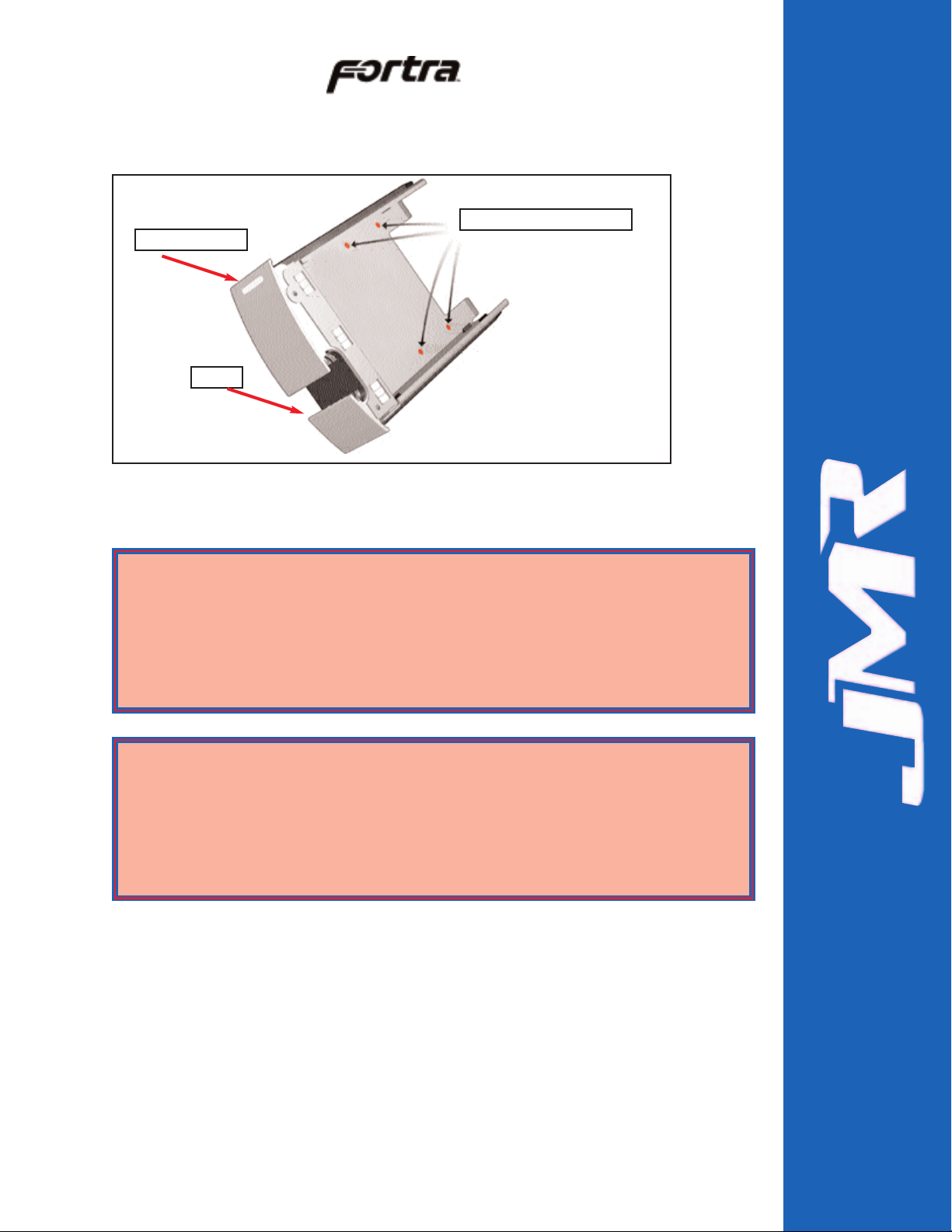
Drive Installation
Device mounting screws are included with the unit for device mounting. The
JMR part number for the #6-32" mounting screws is HDS-01906.
1. After removing the canister, place it on a static free surface along with the
device to be installed.
2. Place the device in the canister and mount it using the provided screws
(use 4 screws to mount the drive).
3. Replace the canister into the unit by following the steps for Removal of a
Device Canister but in reverse order.
FORTRAH1 Chaparral G5312 Installation Guide Rev C
3-2
Device Mounting Holes (4)
Status Indicators
Handle
WARNING: Before device installation, alleviate any electro-static discharge by
touching a grounded metal assembly. Static can be potentially damaging
to enclosure components.
WARNUNG: Berühren Sie vor der Festplatteninstallation geerdete
Metallgegenstände, um elektro statische Aufladung abzuleiten. Statische
Aufladung kann elektronische Gehäusekomponenten schwer beschädigen.
WARNING: The #6-32 mounting screws that are provided have been specially
designed to fit the canisters. Do not install the device using screws
other than the ones provided.
WARNUNG: Die mitgelieferten Befestigungsschrauben #6-32 wurden speziell
für die Einschübe angefertigt und zur Befestigung der Festplatte sollten
Sie keinesfalls andere als diese verwenden.
Page 14

4. Repeat steps 1 through 3 until all devices are installed, then move onto
step 5 to complete unit setup and installation.
5. For 10-bay rackmount units, refer to Chapter 7
to install the enclosure
into a cabinet.
6. Establish host connection. See Chapter 4
for SCSI host connection.
FORTRAH1 Chaparral G5312 Installation Guide Rev C
3-3
Page 15
FORTRAH1 Chaparral G5312 Installation Guide Rev C
4-1
This chapter covers SCSI device setup and option settings. Please take note of the
installation warnings below before beginning setup.
Slot Settings
The pictures below show the slot numbering sequence and the default ID settings.
Channel A and B default ID settings are factory set and can only be changed by using
the SAF-TE Test Utility. Refer to Chapter 9
for SAF-TE utility setup and use.
WARNING: Take care when connecting the unit to an AC power source to
ensure that it is plugged-in to a circuit of the appropriate rating (110v or
220v). For safe operation, the circuit should have over-current protection
to prevent damage to the unit in the event of circuit overloading.
WARNUNG: Vergewissern Sie sich, daß die Netzspannung (220V / 110V)
korrekt eingestellt ist, bevor Sie das Gerät mit dem Stromnetz verbinden.
Zur Sicherheit sollte das Netz über einen Überspannungsschutz zur
Vermeidung von Schäden im Falle einer Überlast verfügen.
WARNING: When connecting the unit to an AC outlet or power strip, ensure
that the outlet has the proper connection for grounding. The AC power
cables included with the unit have three prongs, one of which is used for
the ground connection. Do not use a two prong AC cable with the unit
since this will not allow for proper unit grounding and could cause
problems with normal unit operation.
WARNUNG: Bei der Verbindung der Unit mit einer Steckdose oder einer
Verteilerdose sollten sie auf eine korrekte Erdung derselben achten. Die
mitgelieferten Kaltgeräteanschlußkabel habe 3 Kontakte, von denen
einer zur Erdung verwendet wird. Verwenden Sie kein Stromkabel mit 2
Anschlüssen, da dieses keine korrekte Erdung ermöglicht und Probleme
während des regulären Betriebs verursachen kann.
Slot 0, ID 0
Slot 1, ID 1
Slot 2, ID 2 A
Slot 3, ID 3
Slot 4, ID 4
Slot 5, ID 0
Slot 6, ID 1
Slot 7, ID 2 B
Slot 8, ID 3
Slot 9, ID 4
Slot 9, ID 4
Slot 8, ID 3
Slot 7, ID 2 B
Slot 6, ID 1
Slot 5, ID 0
Slot 4, ID 4
Slot 3, ID 3
Slot 2, ID 2 A
Slot 1, ID 1
Slot 0, ID 0
4. SCSI Setup
Page 16

Available ID's
Each bus is allowed to have ID's that range from 0-15. No two devices on the
same bus may share the same ID. Each host controller always uses one ID. The
on-board SAF-TE processor uses one ID which defaults to ID 5 of bus A.
ID Conflict
When two devices share the same SCSI ID, a conflict occurs. This conflict must
be corrected before the SCSI bus will work properly. If a conflict occurs, check
that no two devices on the bus share the same ID.
Option Settings
Two option settings are located on the personality card. To access the jumpers,
the cover and all controller module canisters must be removed. The diagram
below shows the location of the option settings on the personality card.
Delayed Start Option Jumper
Header W1 pins 1 & 2. (top two pins)
Jumper on = enabled.
Jumper off = disabled (default).
Remote Start Option Jumper
Header W1 pins 3 & 4. (bottom two pins)
Jumper on = enabled.
Jumper off = disabled (default).
FORTRAH1 Chaparral G5312 Installation Guide Rev C
4-2
WARNING: Before opening the cover, disconnect the AC power cord from
both AC inlets to prevent injury.
WARNUNG: Vor dem Entfernen der Abdeckung sind beide 220V Netzkabel
(Kaltgeräteanschlußkabel) zu entfernen, um Verletzungen zu vermeiden.
W1*
Delayed Start
& Remote Start
Page 17

Front Status LEDs
A status indicator is located on each canister. A 'Blue' light indicates normal drive
activity . A 'Red' light indicates a device fault. If all canisters display a 'Red' light
that is blinking on and off it indicates that there is a system fault. A system fault
is either a power supply or blower failure. Check the back of the unit to determine
which fault has occurred. Refer to Chapter 5
for blower fault indicator location
and to Chapter 6
for power supply fault indicator location.
External I/O Connection
The external I/O connections are located on the back of the unit. The figure below
shows the external I/O connections available. The left rear side of the unit is a
mirror of the right side.
The figure below shows the rear I/O connections for the unit along with status
LEDs.
Connections & LEDs
Host Out
SCSI host connection out.
Host In
SCSI host connection in.
FORTRAH1 Chaparral G5312 Installation Guide Rev C
4-3
Status
Indicators
A blue light on a single canister
indicates device activity or busy.
A red light on a single canister
indicates a device fault.
Host Out
Channel A Out
SAF-TE
Fault/Status
RS232
Serial
Connector
SAF-TE
Activity
Host IN
Channel B Out
Not Used
S-Link
Page 18

Channel A Out
HD-68 female connector. Drive connection for daisy-chaining Chan A to other
external enclosures.
Channel B Out
HD-68 female connector. Drive connection for daisy-chaining Chan B to other
external enclosures.
RS232
DB-9, RS-232 Serial Connection for G5312 controller. Use straight through
cable only.
S-ACT
SAF-TE Activity LED. This LED will blink when the is SAF-TE bus activity
between a controller and the JMR SAF-TE processor.
G5312 SCSI Connections
There are four SCSI-2 (LVD) connections on the rear of the 10-bay enclosure.
These connections are used to connect the G5312 controller to SCSI external
enclosures (Channel A Out and Channel B Out). The remaining two SCSI
connections are used to connect to host systems (Host In and Host Out).
G5312 Operating Mode
The only operating mode for the G5312 is the following:
Stand-Alone (Single Controller) Single Host Port - Use this mode with a
single controller when only a single host interface. Channel A and Channel B
are connected internally to five drive bays each and have an external connection
to dasiy-chain to other enclosures (Chan A OUT and Chan B OUT). The
Host In and Host Out connections are used to connect to a host system.
FORTRAH1 Chaparral G5312 Installation Guide Rev C
4-4
Stand-Alone Single
Host Port
SCSI
B OUT
SCSI
A OUT
HOST IN
To/From HOST
Page 19

This chapter covers all operations of the blowers for 10-bay units. Refer to
Chapter 1 for blower specifications. The blowers are hot swappable and can be
removed or installed while the enclosure continues to function, however, failure
to replace a non-working blower within a reasonable period of time may expose
drives to extreme heat, which could cause loss of data.
The blowers are located on the back of the unit
and each has its own fault LED that will light if
the blower is non-operational.
Blower Removal/Insertion
The blower is designed to be easily installed and removed.
1. Unfasten the blower thumbscrew by turning
counterclockwise. A Phillips head
screwdriver can be used if the thumbscrew is
too tight to turn by hand.
2. Remove the blower sled by pulling out on the
handle and grasping the side of the blower
tray. Wait for the blower to stop completely
before removing it from the unit.
Reverse the steps to reinstall the blower.
FORTRAH1 Chaparral G5312 Installation Guide Rev C
5-1
WARNING: Blowers are a system critical component. Non-operating blowers
should be replaced as soon as possible to avoid data loss or device failure.
WARNUNG: Gebläse sind für die Funktion wichtige Komponenten. Nicht
funktionierende Gebläse sollten so schnell wie möglich ersetzt werden,
um Datenverluste oder Fehlfunktionen zu vermeiden.
Fault LED
WARNING: To prevent injury when removing or installing the blower, do not
grab the bottom of the tray which is used for blower access intake. The
blower operates at high speeds and continues to spin for a short time
after power is disconnected.
WARNUNG: Um Verletzungen während der Entfernung oder Installation des
Gebläses zu vermeiden, berühren Sie nicht dessen Unterseite, da hier
der Lufteintritt erfolgt. Das Gebläse arbeitet mit hohen
Geschwindigkeiten und läuft nach Abschalten der Versorgungsspannung
noch einige Zeit nach.
5. Blower Operation
Page 20

User’s removing or installing a blower must be aware of the
blower access hole. Contact with the access hole must be avoided
while the blower is running to prevent injury.
Blower Replacement
If the blower has stopped running or the fault LED indicator is lit, the blower may
need to be replaced. Before replacing, the connection should be checked to ensure
that the connector is firmly seated and that there is nothing blocking the blower
blades that could cause interference.
If a blower is believed to be in a nonfunctional state, please contact the place of
purchase for repair or replacement.
The JMR part number for a replacement blower is shown below. The assembly
includes the tray along with the blower.
Model JMR Part Number
10-bay SBA-04858
FORTRAH1 Chaparral G5312 Installation Guide Rev C
5-2
WARNING: Avoid direct contact with the blower intake access hole while the
blower is running. The blower operates at high speeds and can cause
injury.
Page 21

This chapter covers all operations of the power supplies. For operation, the AC
cord (included) must be connected to the AC Inlet on each supply, and the power
supply must be switched ON. The 'OK LED' will light to indicate the power
supply is functioning properly. If the power supply experiences a problem and
cannot operate within its normal specifications, the Fault LED will light and the
power supply will shut itself off.
The power supplies also have their own fan included to maintain proper cooling
within each supply and also provide some additional, but minimal airflow through
the rest of the enclosure.
Power Supply Removal/Insertion
Follow the following steps to either remove a power supply in a 10/15-bay unit.
1. Unfasten the power supply thumbscrew by turning
counterclockwise. A Phillips head screwdriver
may be used if the thumbscrew is too tight to turn
by hand.
2. Remove by pulling out on the handle.
Reverse the steps to reinstall the power supply.
FORTRAH1 Chaparral G5312 Installation Guide Rev C
6-1
On/Off
Switch
Fault LED
OK LED
Thumbscrew
Handle
AC Inlet
6. Power Supply Operation
Page 22

Low Power Mode (Standby Power)
When both power supplies are turned off, the unit will switch to low power or
standby mode and the power supply fans will continue to run. The unit blowers
will remain operational if a single power supply is turned off, not installed, or
fails, in order to maintain the proper low temperature within the unit. To stop the
power supply fans and turn the unit off completely, it must be disconnected from
the AC power source.
Power Supply Replacement
If the Power Supply Fault LED indicator is lit, the power supply may need to be
replaced. Before replacing, the power supply should be turned off, removed from
the enclosure, and reinstalled. The AC cable connection should be checked to
ensure that the connector is firmly seated and the power supply should be firmly
inserted with the thumbscrew tightly securing it. If the Fault LED indicator is still
coming on, then the power supply should be replaced.
If the fan in the power supply is not functioning but the power supply still works,
the power supply unit should be replaced as soon as possible. Leaving the power
supply running without the fan could cause the power supply to overheat and
shutdown at any time.
If you believe a power supply is in a nonfunctional state, please contact the place
of purchase for repair or replacement.
JMR part number for a replacement power supply is shown below . The assembly
includes the power supply installed in the canister.
Model JMR Part Number
10-bay PSS-00721
FORTRAH1 Chaparral G5312 Installation Guide Rev C
6-2
SAFETY TIP: Both power supplies should be installed into the unit at all times
to maintain proper cooling and airflow within the enclosure. In the event
of a power supply failure, the faulty supply should be left in the enclosure
until a replacement power supply is available.
Page 23

FORTRAH1 Chaparral G5312 Installation Guide Rev C
7-1
This chapter covers the installation of the Rackmount enclosure into a standard
19" (483mm) wide and 30" (762mm) to 36" (914mm) deep cabinet that meets the
EMA/RETMA standards.
Before beginning rail installation, please take note of the following precautions:
NOTE: When installing the unit into a cabinet or closed environment, the
operating ambient temperature of the rack environment may be greater
than the maximum recommended ambient temperature. Consideration
must be taken to meet the maximum recommended ambient temperature
(Tmra) for the best unit operation.
HINWEIS: Wenn das Gerät in einen Gehäuseschrank oder eine sonstige
geschlossene Umgebung verbaut wird, kann die Umgebungstemperatur
über die maximal zulässige Betriebstemperatur ansteigen. Maßnahmen
bzgl. der maximalen, empfohlenen Betriebstemperatur (Tmra) müssen
getroffen werden, um eine bestmögliche Funktion des Gerätes zu
gewährleisten.
WARNING: Ensure that the front and back of the unit are not blocked when
installing the unit into a cabinet or closed area. Blocking the front or
back of the unit can cause reduced air- flow that will compromise the
safe operating environment within the unit.
WARNUNG: Vergewissern Sie sich, daß das Gerät an Vorder- und Rückseite
nicht abgedeckt ist, wenn das Gerät in einem Gehäuseschrank oder
einer geschlossenen Umgebung verbaut wird. Abdeckung der Vorderund Rückseite kann verminderte Kühlung zur Folge haben und somit
sichere Betriebsbedingungen negativ beeinflussen.
WARNING: When loading the unit into a cabinet, ensure that a hazardous
condition is not achieved due to uneven mechanical loading. To prevent
injury, remove the power supplies and drives before loading, and reinstall them after the unit has been secured in the cabinet.
WARNUNG: Vermeiden Sie während des Einbaus des Gerätes in einen
Gehäuseschrank jegliche gefährliche Aktionen, selbst wenn diese nur
mechanischer Art sind. Um Verletzungen zu vermeiden, entfernen Sie
die Netzteile und Laufwerke vor der Montage und installieren Sie diese
erst erneut, wenn das Gerät im Gehäuseschrank gesichert
ist.Vergewissern Sie sich, daß das Gerät an Vorder- und Rückseite nicht
abgedeckt ist.
7. FR10 Cabinet Installation
Page 24

Rail Mounting Kit Hardware
• Ten #10-32 Screws
• Four each #8-32 Screws/Washers/Nuts
Spare Hardware Parts
Check with a JMR Sales Representative for pricing and availability of spare
hardware parts.
Description JMR Part Number
#10-32 Screw HDS-01580
#8-32 Screw HDS-00350
#8-32 Nut HDN-00040
#8-32 Washer HDW-00080
Rail Installation
A completed rail assembly without the unit installed would look like this:
1. Affix the extension brackets to the main rail using the #8-32
screw/washer/nut assemblies. Adjust to the correct length for the cabinet
depth being used.
FORTRAH1 Chaparral G5312 Installation Guide Rev C
7-2
Two #1032 screws
Two #8-32 screw
assemblies
Two #10-32
screws
Cabinet/Unit
Front
Page 25

2. Affix the extension bracket to
the rear of the unit using two
#10-32 screws. There are 3
holes in the extension bracket
for mounting. Depending on the
hole pattern that is being used in
the cabinet, two holes should
always be available for securing
the extension bracket.
3. The fronts of the rails
have three holes. Two of
the holes (top and
bottom) are used to
secure the rail to the
cabinet. The middle
hole is used to secure the
enclosure to the rail and
cabinet. Secure the front
of each rail to the cabinet
vertical rails using two
#10-32 screws for each
rail.
FORTRAH1 Chaparral G5312 Installation Guide Rev C
7-3
Extension Bracket
Two #10-32
screws to secure
rail to cabinet.
Page 26

4. Slide the unit into the cabinet and secure it to the cabinet with a single
#10-32 screw on each side.
5. Snap the end cap over the screw on each side of the unit to finish the
installation.
FORTRAH1 Chaparral G5312 Installation Guide Rev C
7-4
Page 27

The FORTRAH1 Chaparral G5312 is designed to be used with one G5312 SCSI
to SCSI RAID bridge controller from Chaparral. The unit provides one SCSI LVD
SCSI-2 host connection and two SCSI LVD SCSI-2 (80MB/s) device channels
which are backwards compatible with SE SCSI.
The figure below shows the rear unit view where all of the I/O and power
connections are made. Additionally, each controller can be removed from the
back of the unit and the power supplies and blowers may be hot-swapped from
the rear of the unit.
Installation Steps
1. If the G5312 controller is not installed in canisters, then install the controller
into the JMR canister provided and plug into the unit. See Section,
'Controller Canister Installation'.
2. Install up to 10, 3.5" LP SCSI hard disk drives into the device canisters
using 4 screws per device (Screws have been provided - JMR P/N HDS-
01906) for mounting, and install into the front of the unit. Refer to Chapter 3
for drive installation.
3. Configure additional option settings as required. Refer to Chapter 4
for
option settings.
4. Plug in the two AC power cords to the AC inlet located on each power
supply in the rear of the unit. Turn both power supplies on using the on/off
switch located on each power supply.
5. Use a straight through DB-9 serial cable to communicate to the controller(s)
for RAID array creation and setup. Refer to Chaparral documentation for
correct serial port settings.
6. After the RAID set has been created, connect the Fibre channel host I/O
port(s) to a HBA and configure the RAID array in the O/S environment.
FORTRAH1 Chaparral G5312 Installation Guide Rev C
8-1
8. Installing the G5312
G5312 Controller
Canister
Page 28

ID Settings & Option Jumpers
Refer to Chapter 4
and Chapter 9 for SCSI ID settings and option jumper settings.
Controller Canister Installation
1. Remove the four cover screws on the controller canister using a Phillips head
screwdriver and lift the cover off the canister.
2. Mount the controller into the canister with four screws that are provided
inside of the canister.
3. Connect the backup battery to the controller.
4. Connect the cover fan to the controller and close the canister cover. Replace
the 6 screws from Step 1 to secure the cover.
5. Install the controller canister into the Fortra unit.
FORTRAH1 Chaparral G5312 Installation Guide Rev C
8-2
Page 29

FORTRAH1 Chaparral G5312 Installation Guide Rev C
9-1
For bus management, the FORTRA10-bay SCSI RAID enclosures have a
SAF-TE (SCSI Accessed Fault-Tolerant Enclosure) processor designed to the
ANSI approval version 2.0 of the SAF-TE specification. Test utility software is
provided for setup and diagnostics of the SAF-TE processor. The SAF-TE
processor can monitor and manage all devices including itself. There does not
need to be any devices installed in the unit to communicate with the SAF-TE
processor.
SAF-TE ID
The SAF-TE board has a SCSI ID that defaults to SCSI ID 5. This default ID can
be changed using the JMR SAF-TE Setup utility software. Ensure that no other
devices on the channel conflict with the SAF-TE SCSI ID. The SCSI ID settings
made using the SAF-TE processor will always override any hard ID jumper
settings on the unit.
Minimum System Requirements
FORTRAunit with SAF-TE
386 processor or better
3.5" floppy drive (1.44 MB)
4 MB RAM
1.5MB free hard disk space
SAF-TE compatible host adapter
ASPI manager installed
MS-DOS 5.0 or higher, Windows 95 & 98 DOS mode supported (Windows NT
& 2000, UNIX are NOT supported).
The utility software is for set-up and diagnostics only. It can be used to access
SAF-TE commands for setup purposes even when a SAF-TE compatible host
adapter is not installed.
Software Installation
Before installing the software, ensure that the minimum system requirements
have been met. A SCSI host adapter must be installed and connected to the unit.
The host system must be running a compatible operating system and have a host
controller compatible ASPI manager installed. The SCSI host adapter must
recognize the SAF-TE processor on the bus in order for the software to
communicate with the enclosure.
NOTE: The SAF-TE chip ID will only operate at SCSI ID’s 0-7. DO NOT set the
SAF-TE ID outside this range as it will render the SAF-TE chip inoperable.
9. SAF-TE Operation
Page 30

DOS Installation
1. Insert the JMR Utility disk into the floppy drive.
2. Change to the floppy drive that the JMR Utility disk is in.
Example: At the DOS command prompt, type A: and press ENTER.
3. At the disk command prompt ( A:\> ), type CD DOS and press ENTER.
4. Type INSTALL, and press ENTER.
5. This will install the files to the directory C:\JMR by default.
6. The program will switch to the C:\JMR directory.
7. At the C:\JMR> prompt, type JMRSAFT and press ENTER to execute the
software.
8. See the Software Walkthrough section for information on using the program.
9. To uninstall the software, type UNINSTAL and press ENTER from the
C:\JMR directory.
Windows 95 & 98 Installation
1. From the Windows taskbar, click START, and then click RUN.
2. In Open, type A:\WIN\SETUP.EXE and then click OK.
3. The installation program will guide you through the rest of the setup process.
Icons will be created to run the program. Click on the JMR SAF-TE/SES
Icon to run the program.
4. See the Software Walkthrough section for information on using the program.
5. To uninstall the software, run the uninstall program located in the JMR
folder created during installation.
Software Walkthrough
This section covers the operation of the JMR SAF-TE utility software that is
included with a SAF-TE enabled FORTRA
. Part 1 details the basic software
overview. Part 2 details the software commands available to a FORTRA
unit
with SAF-TE.
Software Controls
Use the arrow keys to navigate within the software and use the ESC key to back
up to the previous menu. To select a menu item press ENTER. A two-button
mouse can also be used to navigate through the menu's. The LEFT mouse button
is the same as pressing ENTER and the RIGHT mouse button is the same as
pressing ESC.
Part 1 Basic Software Overview
After loading the software as directed in the
Software Installation section, the main
screen will appear. The top of the screen
shows the title bar and version of the
software. Select the Select Host Adapter
command.
FORTRAH1 Chaparral G5312 Installation Guide Rev C
9-2
Page 31

The following Figure shows
the host adapter selection
screen.
From this screen the host
adapter to be communicated
with can be chosen. The
example shows that there are
two host adapters installed in
the system.
This next screen shows how
the target device may be
selected. Different options
are available depending on
the device selected. If a
SAF-TE device is selected,
the next menu will display
any available SAF-TE
commands. If a disk drive,
CD-ROM, or other media
device is selected, the next
menu will display any
available commands that are
pertinent to that device.
This next screen shows the
Main Device Screen and lists
the commands available. The
Main Device Screen lists the
commands available to a CDROM drive, hard disk drive,
or other SCSI peripheral
selected. The commands are:
Test Unit Ready, Inquiry,
Read Capacity, and Spin
up/down Unit. These
commands are described in
more detail in the next five
screens. The bottom of the
screen shows the host adapter and target that have been selected.
FORTRAH1 Chaparral G5312 Installation Guide Rev C
9-3
Page 32

This next screen shows the Test Unit
Ready Screen. If the unit is online
and ready, the dialog box will report
Target [x] Ready. If the unit is
offline, the dialog box will report
Target [x] Not Ready. 'x' is the
number of the target that was selected
previously and any commands that
are initiated will only affect that
target. To select a different device,
use the ESC key to back up a menu
and select it.
This next screen shows the Inquiry
Screen that is used to report
information on the device as read
from the device itself. Since this
information is from the device, the
information will vary. The Product
ID typically shows a model number
of the device and the Product
Revision Level will typically show
the firmware revision the device is
currently using. The other
information on this screen applies
only under circumstances when
troubleshooting is necessary.
This screen shows the Read
Capacity Screen which reports the
capacity settings and configuration of
the target device.
FORTRAH1 Chaparral G5312 Installation Guide Rev C
9-4
Page 33

This screen shows the Spin
up/down Unit Screen.
These commands are only
effective when using hard
disk drives. The Spin up
Unit command will power
on the target device. The
Spin down Unit command
will power off the target
device. Just as a precaution,
it is safer to spin a device
down before removing it to
prevent damage.
Part 2 FORTRASAF-TE Commands
This screen shows the command menu available if a FORTRASAF-TE device
ID is selected at the SCSI Device Selection Screen.
There are several commands available in the menu screen shown and they are
briefly described in the ‘Command Overview’ section.
FORTRAH1 Chaparral G5312 Installation Guide Rev C
9-5
Page 34

Command Overview
FORTRAH1 Chaparral G5312 Installation Guide Rev C
9-6
Test Unit Ready Reports if communication is established between a host
adapter and the SAF-TE processor.
Inquiry Reads device firmware and identifies device part
number, firmware revision and other information.
Enclosure Config Displays the enclosure configuration.
Enclosure Status Indicates temperature, SCSI ID settings, blower and
power supply status.
Usage Statistics Reports on/off cycles and total number of power on
hours.
Device Insertion
Reports how many times a device has been inserted in
each slot.
Slot Status Reports the status of the device in each slot.
Power Supply Ena/Dis Enables or disables selected power supply.
Fan Setup
Manual fan/blower control allows for slowing down,
speeding up, or turning off fans (does not affect the
power supply fans).
SCSI ID Setup
Change the ID of the selected slot (valid ID's are
between 0-15).
Slot Operation Set or clear slot status flags.
Global Command Set or clear global enclosure flags.
Firmware Options
Allows for firmware upgrades and permanent setting
changes.
Display cdb Window Reserved.
Host/target Menu Returns to Main Screen.
Web Service
Allows for enclosure monitoring over internet/intranet
applications (additional software required).
Page 35

The Inquiry Screen lists
some of the settings of the
unit that may be useful
during troubleshooting. The
Vendor ID, Product ID, and
Product Revision Level are
shown at the bottom of the
screen. When
troubleshooting, it is
important to check that the
Product Revision Level is at
the most recent. In the
example, the product
revision level shown is 1.00.
The Enclosure Config
Screen, shows what
components the enclosure
has been setup to recognize.
Components listed include
Fans, Power Supplies,
Canister Slots, Door Lock,
Temperature Sensors, and
Speaker. This screen does
not show the status of these
components, the Enclosure
Status Screens will show
status.
It is important to note that the enclosure has been programmed with the
information on this screen and that information can be changed using the
Firmware Option menu if a different setup is required. For example; If a power
supply is removed, the enclosure configuration will still report that the number of
power supplies is '2'.
FORTRAH1 Chaparral G5312 Installation Guide Rev C
9-7
Page 36

The Enclosure Status Screen, will
report the status of the blowers,
power supplies, slot SCSI ID's,
system temperature, and slot
temperature. The Usage Statistics
Screen, will report how many hours
the system has been in operation for
and how many times it has been
turned on and off.
The Device Insertion Screen, show
how many times a device has been
inserted into each slot.
The Slot Status Screen, will report
what the status of each slot is. For
testing purposes, the slot status may
be set and cleared from the Slot
Operation menu.
FORTRAH1 Chaparral G5312 Installation Guide Rev C
9-8
Page 37

The Power Supply Ena/Dis Screen,
allows each power supply to be
turned off (disable), or turned on
(enable). From the rear of the unit,
power supply 1 is on the left hand
side, and power supply two is on
the right hand side.
The Fan Setup Screen, allows for
manual control of the blowers.
Individual blower control is not
available so using these commands
will set both blowers at the same
time.
The SCSI ID Setup Screen, allows each slot ID to be changed on-the-fly. Any
changes to these settings will be saved to the unit upon exiting the program. SCSI
ID's can be viewed using the Enclosure Status menu. This menu screen has two
submenus; on the first submenu, the slot must be selected as shown on the left
screen. On the second submenu, the new ID for the selected slot must be chosen.
Use the ESC key to back out of the menu if an incorrect choice is selected. After
changing the ID, go to the Enclosure Status menu to ensure that it has been
changed successfully.
FORTRAH1 Chaparral G5312 Installation Guide Rev C
9-9
Page 38

The Slot Operation Screen, allows flags to be set for each individual slot. The
menu has two submenus; first select the slot and second, select the operation to
be performed on the selected slot. After a selection of the slot, status may be
checked in the Slot Status Screen. The first four commands are important to
canister operation and the rest of the commands are for test purposes. Prepar e Slot
for Operation turns the slot on. Prepare for Insertion/Removal turns the slot off.
Identify Slot will blink the activity LED on the particular slot so that the canister
can be easily located. Clear Slot Errors removes all flags from the slot and clears
all errors to the slot.
The Global Command Screen, has
several flags that may be set that
affect the entire enclosure, not just
a particular slot. The first two
commands are important to unit
operation and the rest of the flags
are mainly used for test purposes.
Clear Global Errors will clear
any enclosure error flags that have
been set
FORTRAH1 Chaparral G5312 Installation Guide Rev C
9-10
Page 39

The Firmware Options
screen is used to read the
current firmware settings of
the unit and to load new
settings into the unit from
disk.
The Display EEPROM
command will show the
current firmware settings.
Display disk File will load
an EEPROM file from a disk
and display it to the screen.
Save EEPROM to disk will
save the current firmware in the unit to a disk. Load EEPROM from disk will load
the EEPROM file from a disk and save it in the unit as the new active firmware.
The Program EEPROM with default command will restore factory default
settings to the unit. See the section Updating Firmware, for specific information
on using these commands and changing firmware settings.
Updating Firmware
T o change enclosure settings including unit SAF-TE ID, default boot options, and
to upgrade the firmware, a Firmware Option menu, seen above, is provided in
the utility software.
To modify existing settings, the settings file (Eetbl.asm) on the utility disk must
be edited to the required settings and then loaded into the unit EEPROM using the
Load EEPROM from Disk command from the Firmware Option menu. The
setting file, Eetbl.asm, is shown with detailed descriptions below. The
HEADING column may be disregarded. The LINE column does not exist in the
file and has been added so that reference to specific rows can be made for
instructional purposes only. Use a text editor to change the value in the
SETTING column, save the file, and then load the file into the EEPROM from the
Firmware Options menu. The DESCRIPTION column contains no setting values
and anything after the semi-colon is a comment in the file.
FORTRAH1 Chaparral G5312 Installation Guide Rev C
9-11
Page 40

EETBL.ASM Default Settings File
LINE HEADING SETTING DESCRIPTION
1 EEDFTTBL: DB 85 ;55H CHECKSUM
2 DB 255 ;0FFH
3 DB 0 ;NONE = 0, MASTER = 1, SLAVE = 2
4 DB 10 ;NUMBER OF CANISTERS
5 DB 11 ;CANISTER SETTINGS WITH-OUT ID
6 DB 5 ;SAF-TE SCSI ID
7 DB 255 ;SPIN-UP TIME LOW BYTE
8 DB 32 ;SPIN-UP TIME HIGH BYTE
9 DB 5 ;TEMP CALIBRATION VALUE (RESERVED)
10 DB 0 ;KEYBOARD LOCK (NOT USED)
11 DB 0 ;SLOT 0 SCSI ID
12 DB 1 ;SLOT 1 SCSI ID
13 DB 2 ;SLOT 2 SCSI ID
14 DB 3 ;SLOT 3 SCSI ID
15 DB 4 ;SLOT 4 SCSI ID
16 DB 0 ;SLOT 5 SCSI ID
17 DB 1 ;SLOT 6 SCSI ID
18 DB 2 ;SLOT 7 SCSI ID
19 DB 3 ;SLOT 8 SCSI ID
20 DB 4 ;SLOT 9 SCSI ID
21 DB 5 ;SLOT 10 SCSI ID
22 DB 8 ;SLOT 11 SCSI ID
23 DB 9 ;SLOT 12 SCSI ID
24 DB 10 ;SLOT 13 SCSI ID
25 DB 11 ;SLOT 14 SCSI ID
26 DB 5 ;SLOT 15 SCSI ID
27 DB 8 ;SLOT 16 SCSI ID
28 DB 9 ;SLOT 17 SCSI ID
29 DB 10 ;SLOT 18 SCSI ID
30 DB 11 ;SLOT 19 SCSI ID
31 DB 12 ;SLOT 20 SCSI ID
32 DB 13 ;SLOT 21 SCSI ID
33 DB 14 ;SLOT 22 SCSI ID
34 DB 12 ;SLOT 23 SCSI ID
35 DB 13 ;SLOT 24 SCSI ID
36 DB 14 ;SLOT 25 SCSI ID
37 DB 0 ;LSB NUMBER OF POWER ON MINUTES
38 DB 0 ; NUMBER OF POWER ON MINUTES
39 DB 0 ; NUMBER OF POWER ON MINUTES
40 DB 0 ;MSB NUMBER OF POWER ON MINUTES
41 DB 0 ;NUMBER OF INSERTION IN SLOT 0 LSB BYTE
42 DB 0 ; MSB BYTE
43 DB 0 ;NUMBER OF INSERTION IN SLOT 1 LSB BYTE
FORTRAH1 Chaparral G5312 Installation Guide Rev C
9-12
Page 41

44 DB 0 ; MSB BYTE
45 DB 0 ;NUMBER OF INSERTION IN SLOT 2 LSB BYTE
46 DB 0 ; MSB BYTE
47 DB 0 ;NUMBER OF INSERTION IN SLOT 3 LSB BYTE
48 DB 0 ; MSB BYTE
49 DB 0 ;NUMBER OF INSERTION IN SLOT 4 LSB BYTE
50 DB 0 ; MSB BYTE
51 DB 0 ;NUMBER OF INSERTION IN SLOT 5 LSB BYTE
52 DB 0 ; MSB BYTE
53 DB 0 ;NUMBER OF INSERTION IN SLOT 6 LSB BYTE
54 DB 0 ; MSB BYTE
55 DB 0 ;NUMBER OF INSERTION IN SLOT 7 LSB BYTE
56 DB 0 ; MSB BYTE
57 DB 0 ;NUMBER OF INSERTION IN SLOT 8 LSB BYTE
58 DB 0 ; MSB BYTE
59 DB 0 ;NUMBER OF INSERTION IN SLOT 9 LSB BYTE
60 DB 0 ; MSB BYTE
61 DB 0 ;NUMBER OF INSERTION IN SLOT 10 LSB BYTE
62 DB 0 ; MSB BYTE
63 DB 0 ;NUMBER OF INSERTION IN SLOT 11 LSB BYTE
64 DB 0 ; MSB BYTE
65 DB 0 ;NUMBER OF INSERTION IN SLOT 12 LSB BYTE
66 DB 0 ; MSB BYTE
67 DB 0 ;NUMBER OF INSERTION IN SLOT 13 LSB BYTE
68 DB 0 ; MSB BYTE
69 DB 0 ;NUMBER OF INSERTION IN SLOT 14 LSB BYTE
70 DB 0 ; MSB BYTE
71 DB 0 ;NUMBER OF INSERTION IN SLOT 15 LSB BYTE
72 DB 0 ; MSB BYTE
Important Settings
Line 6: Contains the default SAF-TE SCSI ID for the enclosure.
Line 11 - 36: Contains default canister SCSI ID settings for the enclosure
(Lines 11 - 20 are for Slots 0-9, the remaining 21 - 36 lines are not typically used)
Line 37 - 40: Contains the amount of power on time
Line 41 - 72: Contains the number of insertions per slot
SAF-TE Commands
This section covers the SAF-TE commands that are implemented in the enclosure. The SAFTE Processor in the enclosure is referred to as the SEP. It is possible that some of the
commands may also be accessed through a host controller menu if the host controller has
implemented the same commands. The commands that are not marked with a '*' are
mandatory SAF-TE commands and must be implemented by the host adapter for basic
communication to the enclosure.
Not all of the commands listed here are required to be implemented in order to be SAF-TE
compliant. The commands that are optional and are not required in order to meet the SAF-TE
specification but are specified within the specification have been marked with a '*' before the
FORTRAH1 Chaparral G5312 Installation Guide Rev C
9-13
Page 42

command. JMR Electronics, Inc. has implemented all of the SAF-TE commands
in the SAF-TE specification including the optional commands, to ensure
compatibility with other vendors. All of the SAF-TE commands can be accessed
through the utility software even if the host adapter has not implemented it or does
not support the command.
SAF-TE does not require that any additional cabling be installed between the
enclosure and the host. Since the enclosure is assigned an ID on the SCSI bus, all
of the communication between the host and enclosure takes place over the SCSI
bus. For SAF-TE to function, both the enclosure and the host adapter must
support the SAF-TE specification and be connected on the same bus in order to
communicate. The SEP in the enclosure is a passive target and will not execute
these commands unless an initiator host controller requests it.
Perform Slot Operation Command
Perform slot operation is a mandatory SAF-TE command that is used to perform
various operations on device slots. The available operations are listed below.
Prepare for operation
Requests that the enclosure SEP should take any action required to make
the device in the selected slot available on the SCSI bus. This powers up
the slot.
Prepare for insertion or removal
Requests that the enclosure SEP should take any action required to allow
the safe physical insertion or removal of a device from the selected slot.
This powers down the slot.
Identify
Requests that the enclosure SEP should indicate the physical location of
the selected slot. This causes the selected slot activity LED to blink.
Read Device Slot Status Command
Read device slot status is a mandatory SAF-TE command that returns information
on the current state of each drive/slot. The available status reports are described
below:
Device Inserted
Reports whether or not there is a physical device inserted in the slot
selected.
Ready for Insertion/ Removal
Reports whether or not the slot is ready for the physical insertion or
removal of a device.
Prepared for Operation
Reports whether or not the slot is activated so that the inserted drive may
be accessed on the SCSI bus.
FORTRAH1 Chaparral G5312 Installation Guide Rev C
9-14
Page 43

Read Enclosure Configuration Command
Read enclosure status is a mandatory SAF-TE command that reports to the host
what components are installed in the enclosure. This will only read the unit that
the SEP is installed on, not any unit connected via S-Link.The components that
can be monitored are listed below:
Number of Fans
Reports the number of currently installed cooling fans.
Number of Power Supplies
Reports the number of currently installed power supplies.
Number of Device Slots
Reports the total number of device slots available in the unit whether or
not a device is inserted.
Door Lock Installed
Reports whether or not a door lock is installed. If there is a lock installed,
the remote lock/unlock feature is a manual procedure and is not hostcontrollable.
Number of Temperature Sensors
Reports the number of temperature sensors installed.
Speaker Installed
Reports if a speaker or buzzer is installed in the unit.
Read Enclosure Status Command
Read enclosure configuration is a mandatory SAF-TE command. This command
is used to find the status of the enclosure components that are listed by the 'Read
Enclosure Configuration Command'. The components and possible status values
are listed below:
FORTRAH1 Chaparral G5312 Installation Guide Rev C
9-15
Blower Power Supply Slot SCSI ID Door Lock Speaker Temperature
Operational Operational and on Slot 'x' = SCSI Installed Off Temperature in Fahrenheit
ID 'x' from -10 to 245
Malfunctioning Operational and off Not On Out of Range
Installed
Not Installed Malfunctioning and
commanded on
Unknown Malfunctioning and
commanded off
Not Present
Present (on or off)
Unknown
Page 44

Send Global Command
Send global command is a mandatory SAF-TE command that is used to send
commands that apply to the entire enclosure globally rather than to a specific
device, channel, or device slot. Global commands set a flag on the enclosure SEP
that can give several results as listed below:
Write Device Slot Status Command
Write device slots status is a mandatory SAF-TE command. These commands
affect the device slots and can only be set from a host adapter. Device Slot Status
commands set a flag on the enclosure SEP that can give several results as listed
below:
FORTRAH1 Chaparral G5312 Installation Guide Rev C
9-16
SYSTEM FAULT Indicates that a global error condition has occurred
as determined by the host adapter.
WARNING FAULT Condition is determined by the host adapter.
COOLING FAULT Indicates that a blower/temperature failure has
occurred.
POWER SUPPLY FAULT Indicates that system power has been lost.
DRIVE FAULT Indicates that a drive has failed.
DRIVE 'x' FAULT Indicates that a potential error has or may have
occurred on a drive.
ARRAY FAULT Indicates that an array has failed.
CRITICAL FAULT Indicates that an array is not fault-tolerant.
ARRAY FAULT IN SLOT 'x'
Indicates a member of the array has an
error.
CRITICAL FAULT IN SLOT 'x' Indicates that the device is in an array
that has become non-fault tolerant.
DATA PARITY FAULT IN SLOT 'x' Indicates the device is in an array
which is undergoing a parity check
operation.
DATA TRANSFER FAULT IN SLOT 'x' Indicates that the device has exhibited
some hardware or data fault.
NO DRIVE FAULT IN SLOT 'x' Indicates that the slot has no drive
inserted.
PREDICTED FAULT IN SLOT 'x' Indicates that the device has been
tagged by a fault prediction algorithm
as being likely to fail in the near
future.
REBUILDING DRIVE IN SLOT 'x' Indicates that the device is being
rebuilt.
Page 45

Optional SAF-TE Commands
*Activate Power Supply Command
Activate power supply is an optional SAF-TE command that is used to turn the
selected power supply on or off.
*Read Device Insertions Command
Read device insertions is an optional SAF-TE command that returns information
indicating how many times a device has been inserted into each slot in the
enclosure while it was powered on.
*Read Usage Statistics Command
Read usage statistics is an optional SAF-TE command that is used to receive
information on total usage time and number of power-on cycles of the enclosure.
Information supplied by the enclosure to the host is described below.
Total Number of Power on minutes
Reports the total number of minutes that the enclosure has been powered
on. This number is cumulative over the life of the unit.
Total number of power on cycles
This counts the number of times that the enclosure has been powered on.
This number is cumulative over the life of the unit.
*Set SCSI ID Command
This is an optional SAF-TE command that is used to set the SCSI bus ID of any
device slot the SEP can communicate with. Changing a device SCSI ID to an
already used SCSI ID will result in the SAF-TE processor automatically selecting
an unused ID. The bus may need to be rescanned by the host controller before the
new ID is recognized.
*Set Fan Speed Command
This is an optional SAF-TE command that is used to set the fan speed. The fan
speed settings are listed below.
0 - 0% of capacity
1 - 25% of capacity
2 - 50% of capacity
3 - 75% of capacity
4 - 100% of capacity
FORTRAH1 Chaparral G5312 Installation Guide Rev C
9-17
Page 46

FORTRAH1 Chaparral G5312 Installation Guide Rev C
10-1
For current information on this product, including updates to the manual and
technical support related issues, please contact the sales support section of our
web page at www.jmr.com, or you can contact our Technical Support division
directly at the address below.
US Corporate Headquarters
JMR Electronics, Inc.
ATTN: Technical Support Division
20400 Plummer St.
Chatsworth, CA 91311
Customer Support: (818) 739-1140
E-mail: techsupport@jmr
.com
Office Hours: Monday-Friday 8:00 A.M. to 5:00 P.M., Pacific Standard Time
Internet: http://www
.jmr.com
Manual Changes
Revision A - Initial Release.
Revision B - Major reformating
Revision C - Completely changed formatting.
10. Product Support
Page 47

FORTRAH1 Chaparral G5312 Installation Guide Rev C
A-1
Drive Manufacturers
Fujitsu
Internet Address: www
.fcpa.com
Hitachi
Internet Address: www
.hitachi.com
IBM (International Business Machines Corporation)
Internet Address: www
.ibm.com
Maxtor
Internet Address: www
.maxtor.com
Seagate Technology
Internet Address: www
.seagate.com
RAID Controller Manufacturers
Adaptec, Inc.
Internet Address: www
.adaptec.com
Chaparral Network Storage
Internet Address: www
.chaparralnet.com
Digi-Data Corporation
Internet Address: www
.digidata.com
Infortrend Corporation
Internet Address: www
.infortrend.com
Intel ICP VORTEX (Intelligent Computer Peripherals)
Internet Address: www
.icp-vortex.com
Mylex Corporation
Internet Address: www
.mylex.com
Silicon Image, CMD Storage Systems
Internet Address: www
.cmd.com
Appendix A. Drive and Controller
Manufacturers
Page 48

Host Bus Adapter Manufacturers
Adaptec, Inc.
Internet Address: www
.adaptec.com
Antares Microsystems
Internet Address: www
.antares.com
Emulex Corporation
Internet Address: www
.emulex.com
JNI Corporation
Internet Address: www
.jni.com
QLogic Corp.
Internet Address: www
.qlogic.com
FORTRAH1 Chaparral G5312 Installation Guide Rev C
A-2
 Loading...