

Page 1

OPERATOR’S MANUAL
and Set-Up Instructions for
**
UNI-SWIVEL AUGERS
J
USA-15S
USA-15P
J. & M. Mfg. Co., Inc.
P.O. Box 547 Ft. Recovery, OH 45846
Ph: (419) 375-2376 Fax: (419) 375-2708
JMMAN0101 (Rev. 04/02/09) ** Registered Trademark
www.jm-inc.com
Page 2

TO THE DEALER:
Read manual instructions and safety rules. Make sure all items on the Dealer’s Pre-Delivery and Delivery Check Lists
in the Operator’s Manual are completed before releasing equipment to the owner.
The dealer must complete the Warranty Registration Card attached to the front inside cover of this manual and return
to J. & M. Mfg. Co., Inc. at the address indicated on the card. Warranty claims will be denied if the Warranty
Registration Card has not been completed and returned.
EXPRESS WARRANTY:
J. & M. Mfg. Co. Inc. warrants against defects in construction or materials for a period of ONE year. We reserve the right
to inspect and decide whether material or construction was faulty or whether abuse or accident voids our guarantee.
Warranty service must be performed by a dealer or service center authorized by J. & M. Mfg. Co. Inc. to sell and/or
service the type of product involved, which will use only new or remanufactured parts or components furnished by J.
& M. Mfg. Co. Inc. Warranty service will be performed without charge to the purchaser for parts or labor based on the
Warranty Labor Times schedule. Under no circumstance will allowable labor times extend beyond the maximum
hours indicated in the Warranty Labor Times schedule for each warranty procedure. The purchaser will be responsible,
however, for any service call and/or transportation of the product to and from the dealer or service center’s place of
business, for any premium charged for overtime labor requested by the purchaser, and for any service and/or
maintenance not directly related to any defect covered under the warranty. Costs associated with equipment rental,
product down time, or product disposal are not warrantable and will not be accepted under any circumstance.
Each warranty term begins on the date of product delivery to the purchaser. Under no circumstance will warranty be
approved unless (i) the product warranty registration card (attached to the inside of the Operator’s Manual) has been
properly completed and submitted to the equipment manufacturer, and (ii) a warranty authorization number has been
issued by the equipment manufacturer. This Warranty is effective only if the warranty registration card is returned
within 30 days of purchase.
This warranty does not cover a component which fails, malfunctions or is damaged as a result of (i) improper
modification or repair, (ii) accident, abuse or improper use, (iii) improper or insufficient maintenance, or (iv) normal
wear or tear. This warranty does not cover products that are previously owned and extends solely to the original
purchaser of the product. Should the original purchaser sell or otherwise transfer this product to a third party, this
Warranty does not transfer to the third party purchaser in any way. J. & M. Mfg. Co. Inc. makes no warranty, express or
implied, with respect to tires or other parts or accessories not manufactured by J. & M. Mfg. Co. Inc. Warranties for
these items, if any, are provided separately by their respective manufacturers.
THIS WARRANTY IS EXPRESSLY IN LIEU OF ALL OTHER WARRANTIES OR CONDITIONS, EXPRESS, IMPLIED OR
STATUTORY, INCLUDING ANY IMPLIED WARRANTY OF MERCHANTABILITY OR FITNESS FOR PARTICULAR
PURPOSE.
In no event shall J. & M. Mfg. Co. Inc. be liable for special, direct, incidental or consequential damages of any kind. The
exclusive remedy under this Warranty shall be repair or replacement of the defective component at J. & M. Mfg. Co.
Inc’s. option. This is the entire agreement between J. & M. Mfg. Co. Inc. and the Owner about warranty and no J. & M.
Mfg. Co. Inc. employee or dealer is authorized to make any additional warranty on behalf of J. & M. Mfg. Co. Inc.
The manufacturer reserves the right to make product design and material changes at any time without notice. They
shall not incur any obligation or liability to incorporate such changes and improvements in products previously sold to
any customer, nor shall they be obligated or liable for the replacement of previously sold products with products or
parts incorporating such changes.
SERVICE:
The equipment you have purchased has been carefully manufactured to provide dependable and satisfactory use.
Like all mechanical products, it will require cleaning and upkeep. Lubricate the unit as specified. Observe all safety
information in this manual and safety signs on the equipment.
For service, your authorized J. & M. dealer has trained mechanics, genuine J. & M. service parts, and the necessary
tools and equipment to handle all your needs.
Use only genuine J. & M. service parts. Substitute parts may void the warranty and may not meet standards required
for safe and satisfactory operation. Record the model number and serial number of your equipment in the spaces
provided:
Serial No.: Date of Purchase:
Purchased From:
Provide this information to your dealer to obtain correct repair parts.
2
Page 3
UNI-SWIVEL HYDRAULIC AUGERS
SPECIFICATIONS
SPECIFICATIONS USA-15
Diameter 6”
Sizes - Length 15’
Hopper Adjustable to fit almost any make gravity box
Auger Tube 14 Ga. Seamless Steel Tube
Winch Standard
Auger Pivot Uni-Swivel Design (Patent #5,615,990)
Sump Design Hopper Yes
Unloading Height (to steel spout)
Maximum 11 1/2’
Minimum 7’
Height of Auger in Saddle
(on 385SD Box to steel spout) 10’
Maximum Swing Left and Right 31’
Maximum Unloading
Distance Out 13’
Bristle Flighting Optional
Poly-Cup Plastic Flighting Optional
Discharge Rate (corn)* 15 bu./min.
Discharge Rate (soybeans)* 15 bu./min.
Discharge Rate (fertilizer)* 1,000 lbs./min.
* Your rate may differ due to the quality of material, the auger unloading height angle, and variable tractor hydraulic output.
GENERAL INFORMATION
TO THE OWNER:
The purpose of this manual is to assist you in operating and maintaining your header transport in a safe
manner. Read it carefully. It furnishes information and instructions that will help you achieve years of dependable
performance and help maintain safe operating conditions. If this machine is used by an employee or is loaned
or rented, make certain that the operator(s), prior to operating:
1. Is instructed in safe and proper use.
2. Reviews and understands the manual(s) pertaining to this machine.
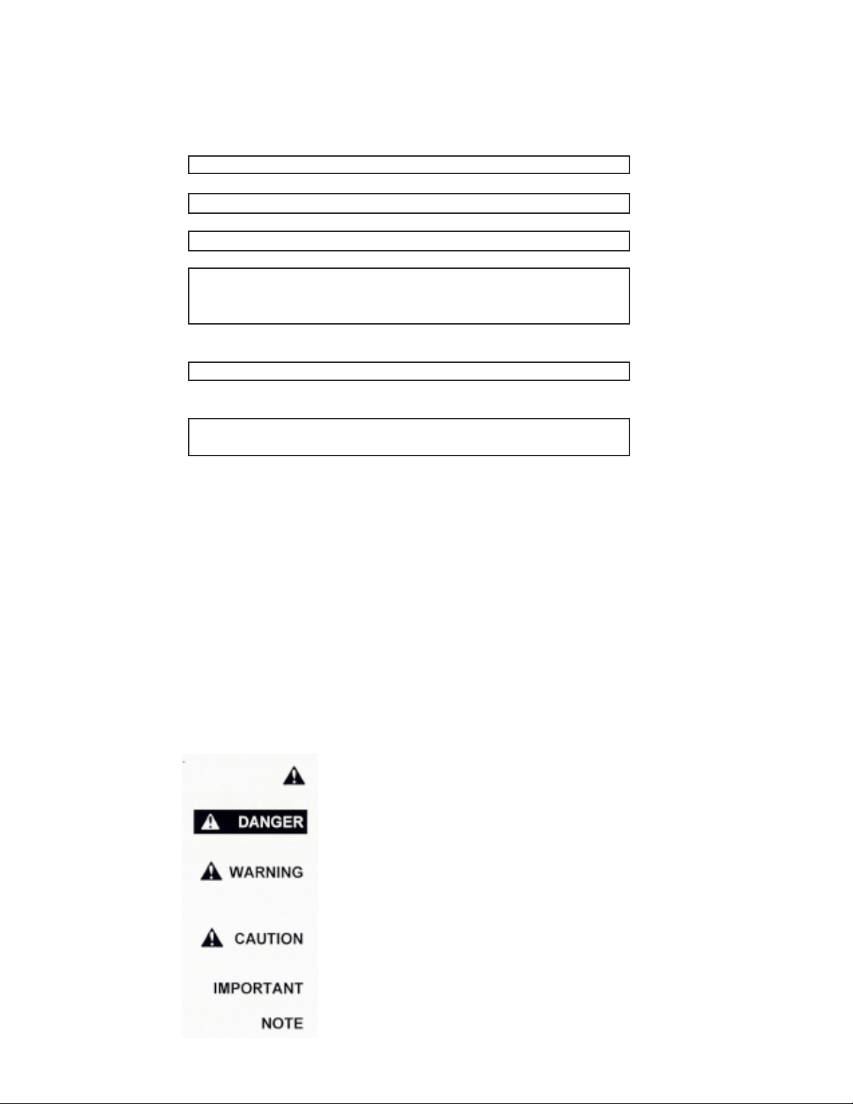
Throughout this manual, the term IMPORTANT is used to indicate that failure to observe can cause damage to
equipment. The terms CAUTION, WARNING and DANGER are used in conjunction with the Safety-Alert
Symbol, (a triangle with an exclamation mark), to indicate the degree of hazard for items of personal safety.
When you see this symbol, carefully read the message that follows and be alert to the possibility of personal
injury or death.
This Safety-Alert symbol indicates a hazard and means
ATTENTION! BECOME ALERT! YOUR SAFETY IS INVOLVED!
Indicates an imminently hazardous situation that, if not avoided, will
result in death or serious injury.
Indicates a potentially hazardous situation that, if not avoided, could
result in death or serious injury, and includes hazards that are
exposed when guards are removed.
Indicates a potentially hazardous situation that, if not avoided, may
result in minor or moderate injury.
Indicates that failure to observe can cause damage to equipment.
Indicates helpful information.
3
Page 4
GENERAL INFORMATION
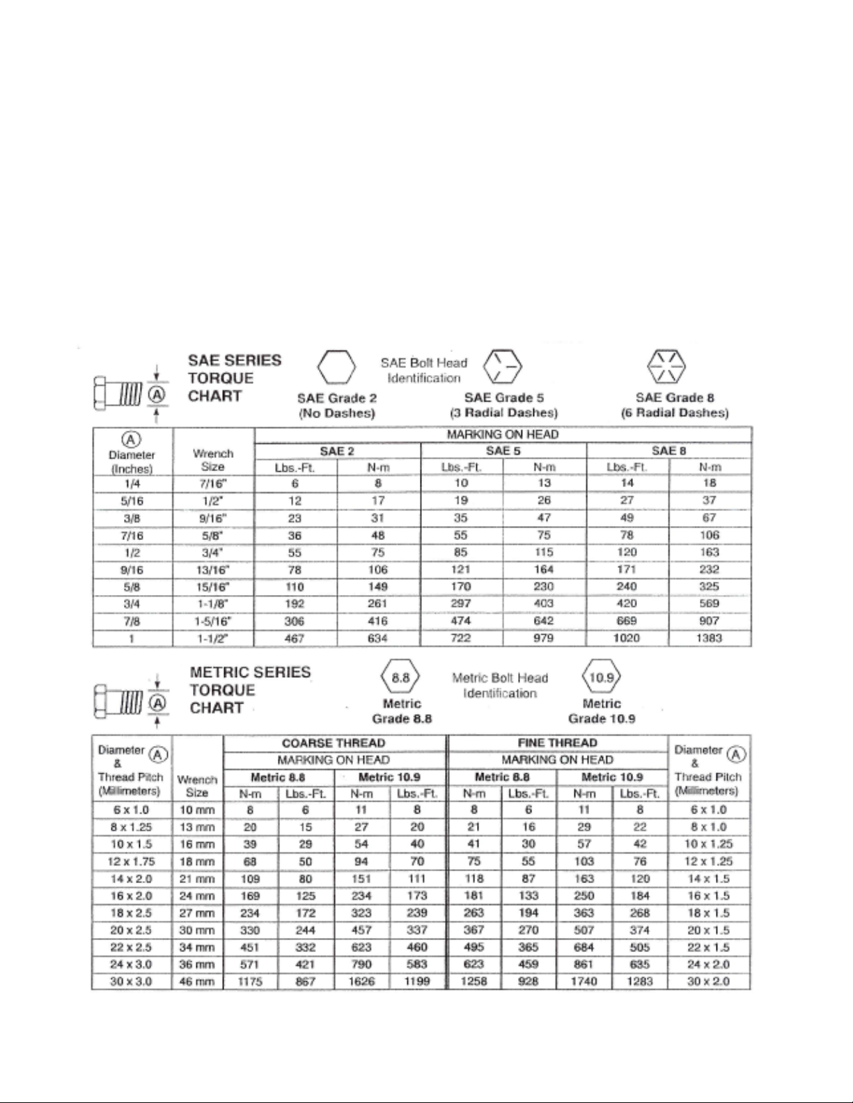
BOLT TORQUE CHART
Always tighten hardware to these values unless a different torque or tightening procedure is listed for a specific
application.
Fasteners must always be replaced with the same grade as specified in the manual parts list.
Always use the proper tool for tightening hardware: SAE for SAE hardware and Metric for metric hardware.
Make sure fastener threads are clean and you start thread engagement properly.
All torque values are given to specifications used on hardware defined by SAE J1701 & J1701M JUL 96.
4
Page 5

TABLE OF CONTENTS
INTRODUCTION 2
EXPRESS WARRANTY 2
SPECIFICATIONS 3
GENERAL INFORMATION 3
BOLT TORQUE CHART 4
SAFETY RULES 6
SAFETY SIGNS 7
SET-UP INSTRUCTIONS 8-9
PARTS LIST 10
INITIAL OPERATION, OPERATING INSTRUCTIONS/MAINTENANCE 11
SERVICE RECORDS 12
5
Page 6

SAFETY RULES
ATTENTION! BECOME ALERT! YOUR SAFETY IS INVOLVED!
Safety is a primary concern in the design and manufacture of our products. Unfortunately, our
efforts to provide safe equipment can be erased by an operator’s single careless act. In addition,
hazard control and accident prevention are dependent upon the awareness, concern, judgement,
and proper training of personnel involved in the operation, transport, maintenance and storage of
equipment.
Make certain that the operator(s), prior to operating is instructed in safe and proper use and reviews
and understands the manual(s) pertaining to this machine.
Read this manual before you operate this machine. If you do not understand any part of this
manual, or need more information, contact the manufacturer or your authorized dealer.
SAFETY
Understand that your safety and the safety of other persons is measured by how you service, and
operate this machine. Know the positions and functions of all controls BEFORE operating this
machine. Make sure to check all controls in a safe area before starting your work.
The safety information given in this manual does not replace safety codes, federal, state or local
laws. Make certain your machine has the proper equipment needed as designated by local laws
and regulations.
Hydraulic oil leaking under pressure can penetrate skin and cause infection or other injury.
To Prevent Personal Injury:
Relieve all pressure, before disconnecting fluid lines.
Before applying pressure, make sure all connections are tight and components are in good
condition.
Never use your hand to check for suspected leaks under pressure. Use a piece of cardboard
or wood for this purpose.
If injured by leaking fluid, see your doctor immediately.
When transporting your hydraulic auger, always keep the auger in the stow position and make sure
that it is properly fastened in the transport bracket. Use care when moving or operating the hydraulic
auger near electric lines as serious injury or death can result from contact.
Never adjust, service, clean or lubricate the hydraulic auger until all power is shut off.
Keep all safety shields in place. Keep hands, feet, and clothing away from moving parts while the
unit is in operation.
Make sure that everyone is clear of the equipment before applying power or moving the machine.
Never position yourself or others underneath the auger. Be sure that the safety cable is secured
properly along with the winch cable.
Make sure that the gravity box is properly fastened to the running gear. Be sure that the gravity box
and attached running gear is large enough to support the weight of the auger when the auger is
extended so as to prevent tipping over of the unit. Do not operate the unit on a slope or side of a hill
as tipping of the unit could occur.
6
Page 7

750-16 OWNER’S MANUAL
SAFETY SIGNS
ATTENTION! BECOME ALERT! YOUR SAFETY IS INVOLVED!
Replace Immediately If Damaged or Missing!
IMPORTANT: Install new safety signs if the old signs are
destroyed, lost, painted over or cannot be read. When
parts are replaced that have safety signs, make sure you
install a new sign with each new part. New signs are
available from the manufacturer or your authorized dealer.
Ref. # Description Part # Req’d
1 Sign, Danger DD-103 1
2 Sign, Danger DD-104 1
3 Sign, Warning DW-106 1
4 Sign, J&M DI-114 2
5 Sign, Warning DW-105 1
6 Sign, Caution DC-110 1
DW-106
DD-104
DD-105
DC-110
DD-103
Set-Up of Uni-Swivel Hydraulic Augers
Comes complete with the following:
1 - Auger Tube, Swivel Assembly, with control rod, top spout
1 - Parts Carton - consists of:
1 - 6” diameter rubber spout x 4’ long
1 - 6” hose clamp
2 - 1/2” hydraulic hose x 84”
1 - winch assembly
1 - 1/2” curved rod x 40”
1 - transport bracket w/ ratchet and tie-down strap
1 - coupler bracket
2 - Flat Attaching Brackets
1 - 3 piece adjustable hopper
1/2” Pulley
(black)
3/16” Pulley
(zinc)
5/16” Pulley
(zinc)
1 - hose holder bracket
1 - owners manual (set-up) w/winch parts list
1 - Parts Bag - consists of:
1 - 3/8” J-Bolt 2 - 3/8” x 1 1/2” Hex Bolts - Gr 2 2 - 3/8” Lockwashers
1 - 6” rubber strap with hooks 35 - 3/8” Hex Lock Nuts 2 - 3/4” Flatwashers
1 - 9” rubber strap with hooks 20 - 3/8” Hex Nuts 2 - 3/16” Hair Pin Clips
1 - 3/16” pulley (zinc) 6 - 3/8” x 3/4” Hex Bolts - Gr 2 2 - 3/8” x 1” Tab Bolt
2 - 5/16” pulley (zinc) small 27 - 3/8” Flat Washers 2 - 5/16” Shackles
1 - 1/2” pulley (black) 18 - 3/8” x 1/2” Stove Bolts 2 - 3/8” Wing Nuts
1 - 3/16” cable x 11’ (winch) 1 - 1/4” Rope Clamp 27 - 3/8” x 1” Hex Bolts - Gr5
1 - 3/16” cable x 7’ (safety) 1 - Plastic Rope Handle 1 - 5/16” Rope x 15’
3 - 3/16” cable clamps 1 - 3/8” x 3/4” Hex Bolt - Gr 8 1 - 3/8” Lock Nut - Gr 8
Tools Required - Hammer, Screwdriver, Drill with 13/32” Bit, 2 Vise-Grips, 2 - 9/16” wrenches, 1 - 7/16”
Wrench (Two persons are needed for set-up)
7
Page 8

UNI-SWIVEL HYDRAULIC AUGER INSTALLATION
Measure the distance between the angle irons to
1
the left and right of the door on your gravity box.
Adjust the dimensions of your hopper to best fit
between the angle irons. Use (6) - 3/8” x 3/4” hex
bolts and lock nuts and 12 washers to fasten the
adjusting ends of the hopper to the center base. Use
the 3/8” x 1/2” stove bolts and nuts to “plug” holes
not used in the adjustment. Attach the Flat Attaching
Brackets to the existing hole in the door angle iron
using the bottom hole in the Flat Attaching Bracket.
Drill 13/32” hole into the door angle iron and secure
the top of the Flat Attaching Bracket using (2) - 3/8”
hex bolts and lock nuts. (Some adjustment may be
required on some makes of gravity boxes). Place
newly assembled Quick-Attach hopper on the gravity
box by guiding the 1-3/4” pins of the hopper wings
down the slots in the Flat Attaching Brackets.
Secure 3/4” Flat Washers on the outside of the Flat
Attaching Bracket by inserting 3/16” hair pins into
the 1-3/4” pins on the hopper wings. Clip 3/8” x 1”
Tab Bolt with Wing Nut to bottom flange of hopper
and attach to angle iron of box under door.
Place the 1/2” curved rod weldment to the top lip of the
2
gravity box by centrally locating it above the door. Drill (4)
- 13/32” holes through the top lip of the box (also through
sideboard lip if so equipped) using the end tap holes as
guides. Attach using (4) - 3/8” x 1” hex bolts, lock nuts
and washers. Secure (1) - 5/16” Shackle to the center
hole in the curved rod weldment. Loop the 3/16” safety
cable through the shackle and securely clamp together
using a 3/16” cable clamp. Position the auger on the
ground below the hopper. (Place on blocks to raise the
auger up.) Lay the safety cable under the 1/2” curved rod
and attach the safety cable to the auger using the top
hole of the auger cable mounting tab by looping the end
of the 3/16” cable through the hole and securing using a
3/16” cable clamp. Lift the base of the auger up to the
bottom of the 3-Piece Adjustable Hopper, align holes, and
attach using (6) - 3/8” x 1” hex bolts and lock nuts. (Note:
Place the front two bolts and lock nuts in first, then visegrip both sides of the hopper to the flange on the auger,
then complete bolting together.)
Flat Attaching
Bracket
3-Piece Adj.
Hopper
3/8” x 1” Stove
Bolt w/ Reg. Nut
3/8” x 1”
Bolt (Gr 5)
w/ washers
and lock nut
Overhead View of 3-Piece Adj. Hopper
3/8” x 1” Bolt (Gr 5) w/ washers and lock nut
52
20
22
28
3/8” x 1”
Bolt (Gr 5)
bolted to box angle iron located beneath door
w/ washers
52
20
19
18
and lock
nut
8
Page 9

UNI-SWIVEL HYDRAULIC AUGER INSTALLATION
Attach the winch assembly to the auger bracket (for normal mounting, the winch handle is on the left side of the
3
auger when facing the box) using (3) - 3/8” x 1” hex bolts, flat washers and lock nuts. Attach the end of the
cable to the winch using the clip on the side of the winch. Spool several rounds of cable onto the winch drum
as per instructions on the winch. Attach the 3/16” pulley (zinc) to the bottom hole of the auger cable mounting
tab using a 3/8” x 1” hex bolt and lock nut. Loop the cable through the 3/16” pulley. Remove the 3/8” bolt from
the center of the 1/2” black pulley and position the 1/2” curved rod between the pulley and the pulley bracket.
Reattach the 3/8” bolt and lock nut. (Do not overtighten.) Attach one 5/16” Shackle to the end of the 1/2” black
pulley bracket. Loop the winch cable through the shackle and secure using a 3/16” cable clamp.
35
10
34
20
52
28
19
22
52
20
20
21
11
30
33
29
19
50
49
6
1
Swing the auger into the stow position (winch
4
handle out). Place the transport bracket under
the reinforcing channel of the auger and against
the side of the gravity box. (NOTE: For
increased support, position the transport
bracket as close as possible to the triangular
corner on the front of the gravity box. Be sure
to allow enough room for the reinforcing back
plate which is positioned inside the gravity
box.) Using the Transport Bracket as a
template, drill (4) 13/32” holes into the side of
the gravity box and attach the Transport
Bracket and Backing Plate using four 3/8” x
1” bolts and lock nuts. Attach the Ratchet to
the Transport Brackets as shown using one
3/8” x 3/4” Grade 8 Bolt and 3/8” Grade 8 Lock
Nut. Secure the Auger to the Transport
Bracket by wraping the tie-down strap around
the auger and inserting the hook through the
hole on top of the Transport Bracket. Ratchet
the strap until the auger is firmly secured.
42
22
17
20
25
31
2
7
32
3
37
Optional 3-Stage
Telescoping Spout
Tie-Down
Hook and
Strap Assy.
3/8” x 3/4”
Grade 8 Bolt
with Lock Nut
Transport
Bracket
Ratchet
9
Page 10

UNI-SWIVEL HYDRAULIC AUGER INSTALLATION
Remove the plastic plugs from the hydraulic motor at the base of the auger and attach the two 1/2” hydraulic
5
hoses. (NOTE: The SUPPLY hose will be the one connected directly to the motor valve and the
RETURN hose will be the one connected to the motor valve.) Attach the coupler bracket to the brace
inside front leg of the gravity box using one 3/8” x 1” bolt and lock nut. Attach hydraulic hoses. Secure the
hydraulic hoses to the box runner using the 9” rubber strap. (Place the rubber strap as close to the center of
the box as possible to keep the hydraulic lines away from the tire.)
Position the Hose Holder Bracket to the side rail (far side) of the ladder. Sandwich the tractor hydraulic hoses
(not included) between the side rail of the ladder and the hose holder bracket using (2) - 3/8” x 1 1/2” bolts and
nuts.
SUPPLY HOSE
RETURN HOSE
Winch the auger down to the lowest position. Attach the 6” rubber spout (or optional 3-Stage Telescoping
6
Spout) using the 6” black clamp. Clamp together using on 3/8” x 1 1/2” bolt and one 3/8” lock nut. Attach the
J-Bolt to the top bracket with hook end on the same side as the control rod. Attach one 5/16” pulley to the JBolt. Attach the other pulley to the control rod. Loop the 5/16” rope through the pulleys and attach to the JBolt. Slip the Plastic Rope Handle onto the rope through the small holes in the handle. Adjust the handle along
the length of the rope to the end of either the 4’ rubber spout or the 3-Stage Telescoping Spout.
J-Bolt
5/16" Pulley
Rope
5/16" Pulley
Control Rod
10
Page 11

UNI-SWIVEL HYDRAULIC AUGER PARTS LIST
# USA-15 Part # Description Qty
1 HS-0405 Hydraulic Motor 1
2 DL-86 Valve with handle 1
3 14-CR Control Rod 1
4 HS-0405S Seal Kit - Motor 1
5 DL-86V Seal Kit - Valve 1
6 HH-7 1/2" Hydraulic Hose x 84" 2
7 6RS-4 6" Diameter Rubber Spout x 4' 1
8 6RS-6 6" Diameter Rubber Spout x 6' 1
9 6RS-12 6" Diameter Rubber Spout x 12' 1
10 HC-6 6" Clamp 1
11 6ST-12 6" Steel Tube with Flange 1
12 SF-15 Steel Flighting complete 1
13 BF-15 Bristle Flighting complete 1
14 PF-15 Plastic Flighting complete 1
15 RA-1 Ratchet 1
16 RS-9 9" Rubber Strap 1
17 WA-1 Winch Assembly 1
18 316C-7 3/16" Cable x 7' (safety) 1
19 316C-10 3/16" Cable x 11' (winch) 1
20 316CC 3/16" Cable Clamp 3
21 316-P 3/16" Pulley (zinc) 1
22 12-P 1/2" Pulley (black) 1
23 3AH 3 Piece Adjustable Hopper 1
24 CA-12 Coupler Bracket 1
25 2C-1 2" Cap for Clean-Out Pipe 1
26 DP-1 Complete Decal Package 1
27 TB-2 Transport Bracket w/backing plate 1
28 12-RW 1/2" Curved Rod Weldment 1
28 12-RWSS 1/2" Curved Rod Weldment (for straight sided box) 1
29 6TS-42 6" Top Spout 1
30 SS-12 6" Sleeve x 12" 1
31 38M-12F Street Elbow 1
32 1PRH Plastic Rope Handle 1
33 516R15 5/16" Rope x 15' 1
34 516-P 5/16" Pulley (small) 3
35 384JB 3/8" x 4" J-bolt 1
36 HHB-1 Hose Holder Bracket 1
37 51617 Compression Spring 1
38 HW-S Hopper Wing, Short, for tapered box 2
39 HW-L Hopper Wing, Long, for tapered box 2
40 HW-SS Hopper Wing, short, for straight sided box 2
41 HW-LS Hopper Wing, Long, for straight sided box 2
42 FAB-1 Flat Attaching Bracket 2
43 38112HB 3/8" x 1 1/2" Hex Bolt - Gr 2 2
44 3812SB 3/8" x 1/2" Stove Bolt 18
45 381-HB 3/8" x 1" Hex Bolt 23
46 38LN 3/8" Lock Nut 31
47 38WN 3/8" Wing Nut 2
48 38LW 3/8" Lock Washer 2
49 34FW 3/4" Flat Washer 2
50 316HP 3/16" Larg Hair Pin Clips 2
51 381TB 3/8" x 1" Tab Bolt 2
52 516-S 5/16" Shackle 2
53 38HN 3/8" Hex Nut 20
54 3834HB 3/8" x 3/4" Hex Bolt 6
55 38-FW 3/8" Flat Washer 27
56 TDS-1 Tie Down Strap and Hook Assembly 1
57 3834G8B 3/8" x 3/4" Grade 8 Hex Bolt 1
58 38LNG8 3/8" Lock Nut (Grade 8) 1
11
Page 12

INITIAL OPERATION / MAINTENANCE
WARNING
BE CERTAIN THAT ALL POWER IS SHUT OFF BEFORE SERVICING THE HYDRAULIC AUGER.
IMPORTANT - Make sure that your tractor delivers a minimum of 9 gallon per minute (1,500 psi), but does not
exceed 15 gallon per minute (2,250 psi). At no time should you operate at 15 gallon per minute and 2,250 psi
at the same time.
Before the hydraulic auger is put into service:
Has the gravity box been fastened properly to the running gear?
Have all nuts, bolts, and braces been properly fastened?
Has all debris and foreign objects been removed from the gravity box and hydraulic auger?
Have the safety instructions been read and clearly understood by the operator(s) of this machine?
OPERATING INSTRUCTIONS
WARNING
BE CERTAIN THAT ALL POWER IS SHUT OFF WHEN CONNECTING HYDRAULIC LINES TO THE TRACTOR.
Preparing the Hydraulic Auger for Use.
Attach the hydraulic lines to the service outlet on the tractor. Make sure that the lines are properly
connected for correct auger rotation. Flighting may become damaged if the system is run backwards.
Make sure that all air is bled from the hydraulic lines.
Run the auger EMPTY before actual use.
A control rod runs the length of the auger tube. Operate the auger from this rod or pull rope. When
possible, try to completely auger out the material from the auger tube after each unloading. This will
reduce stress on the hydraulic system and increase the motor life. Never transport the unit with the
auger tube full of material. If the auger becomes clogged or you option to change the flighting (i.e. steel
flighting to plastic flighting) make sure all power is shut off before servicing.
After use, make sure to clean out well and coat the inside of the auger with oil to inhibit rusting,
especially after handling fertilizer. Also, open the auger cleanout port at the base of the auger tube.
CHANGING THE FLIGHTING
WARNING
BE CERTAIN THAT ALL POWER IS SHUT OFF BEFORE CHANGING THE FLIGHTING.
With the power off, loosen the (4) - 3/8” x 1 1/2” bolts and nuts from the top bracket of the auger. Pull off the top
spout. At the hydraulic motor, remove the 3/8” x 1 3/4” bolt and nut from the motor shaft. Pull out the flighting
from the top. Replace and reattach the flighting to the motor shaft and also reattach the upper spout.
NOTE: PLUGGING THE AUGER EQUIPPED WITH PLASTIC FLIGHTING MAY DAMAGE THE FLIGHTING.
IN ADDITION, DO NOT RUN AN AUGER EMPTY FOR AN EXTENDED PERIOD OF TIME WHEN EQUIPPED
WITH PLASTIC FLIGHTING.
12
Page 13

SERVICE / MAINTENANCE RECORD
DATE DESCRIPTION NOTES
13
 Loading...