

Page 1
O P E R A T O R ’ S M A N U A L
Set-Up Instructions and Parts Catalog for
Torsion-Flex Soil Conditioners
Models
TF2, TF212 and TF215
(serial # 2250 and higher)
12’ to 45’ Working Width
Torsion-Flex Double Rolling Baskets
J. & M. Manufacturing Co., Inc.
P.O. Box 547
Fort Recovery, OH 45846
Phone: (419) 375 2376 Fax: (419) 375-2708
E-mail: sales@jm-inc.com
Website: www.jm-inc.com
REV. 03-28-11
Pg. 1
Page 2

TO THE DEALER:
Read manual instructions and safety rules. Make sure all items on the Dealer’s Pr e-Delivery and Delivery Check
Lists in the Operator’s Manual are completed before releasing equipment to the owner.
The dealer must complete the Warranty Registration Card attached to the front inside cov er of this manual and retu rn
to J. & M. Mfg. Co., Inc. at the address indicated on the card. Warranty claims wi ll be denied if the Warranty
Registration Card has not been completed and returned.
EXPRESS WARRANTY:
J. & M. Mfg. Co. Inc. warrants against defects in construction or materials for a period of ONE year. We reserve the
right to inspect and decide whether material or construction was faulty or whether abuse or accident voids our
guarantee.
Warranty service must be performed by a dealer or service c enter authorized by J. & M. Mfg. Co. Inc. to sell and/or
service the type of product involved, which will use onl y new or remanufactured p arts or components furnished b y J.
& M. Mfg. Co. Inc. Warranty service will be performed without charge to the purchaser for parts or labor based on th e
Warranty Labor Times schedule. Under no circumstance will allowable labor times extend beyond the maximum
hours indicated in the Warranty Labor Times schedule for each warranty procedure. The purchaser will be
responsible, however, for any service call and/or transportation of the product to and from the dealer or service
center’s place of business, for any premium charged for overtime labor requested by the purchaser, and for any
service and/or maintenance not directly related to any defect covere d under the warranty. Costs associated with
equipment rental, product down time, or product disposal are not warrantable a nd will not be accepted under any
circumstance.
Each warranty term begins on the date of product delivery t o the purchas er. Under no circumstance will warranty be
approved unless (i) the product warranty registration card ( attached to the inside of the Operator’s Manual) has been
properly completed and submitted to the equipment manufact urer. This Warranty is effective only if the warranty
registration card is returned within 30 days of purchase.
This warranty does not cover a component which fails, malfunctions or is damaged as a result of (i) improper
modification or repair, (ii) accident, abuse or improper use, (iii) improper or insufficient mainte nance, or (iv) normal
wear or tear. This warranty does not cover products that are previously owned and extends solely to the original
purchaser of the product. Should the original purchaser sell or other wise transfer this product to a third party, this
Warranty does not transfer to the third part y purchas er i n an y way. J. & M. Mfg. Co. Inc. makes no warranty, express
or implied, with respect to tires or other parts or accessories not manufactured by J. & M. Mfg. Co. Inc. Warranties
for these items, if any, are provided separately by their respective manufacturers.
THIS WARRANTY IS EXPRESSLY IN LIEU OF ALL OTHER WARRANTIES OR CONDITIONS, EXPRESS,
IMPLIED OR STATUTORY, INCLUDING ANY IMPLIED WARRANTY OF MERCHANTABILITY OR FITNESS FOR
PARTICULAR PURPOSE.
In no event shall J. & M. Mfg. Co. Inc. be liable for specia l, direct, incidental or consequential dam ages of any kind.
The exclusive remedy under this Warranty shall be repair or replacement of the defective component at J. & M. Mfg.
Co. Inc’s. option. This is the entire agreement between J. & M. Mfg. Co. Inc. and the Owner about warrant y and no J.
& M. Mfg. Co. Inc. employee or dealer is authorized to make any additional warranty on behalf of J. & M. Mfg. Co.
Inc.
The manufacturer reserves the right to make product design and material changes at any time without notice. They
shall not incur any obligation or liab ility to in corporate such changes and i mprovements in pr oducts previousl y sold to
any customer, nor shall they be obligated or liable for the replacement of previously sold products with products or
parts incorporating such changes.
SERVICE:
The equipment you have purchased has b een carefully manufactured to provide dependable and sat isfactory use.
Like all mechanical products, it will require cleaning and upk eep. Lubricate the unit as specified. Observe all s afety
information in this manual and safety signs on the equipment.
For service, your authorized J. & M. dealer has trained mec hanics, genuine J. & M. service parts, a nd the necessar y
tools and equipment to handle all your needs.
Use only genuine J. & M. service parts. Substitute parts may void the warranty and may not meet standards required
for safe and satisfactory operation. Record the model number and serial number of your equipment in the spaces
provided:
Serial # ___________ Purchase Date: _______ Purchased From: ________ ____________________________
Please provide this information to your dealer to obtain the correct parts:
Pg. 2
Page 3
GENERAL INFORMATION
TO THE OWNER:
The purpose of this manual is to assist you in operating and maintaining your running gear in a safe
manner. Read it carefully. It furnishes information and instructions that will help you achieve years of
dependable performance and help maintain safe operating conditions. If this machine is used by an
employee or is loaned or rented, make certain that the operator(s), prior to operating:
1. Is instructed in safe and proper use.
2. Reviews and understands the manual(s) pertaining to this machine.
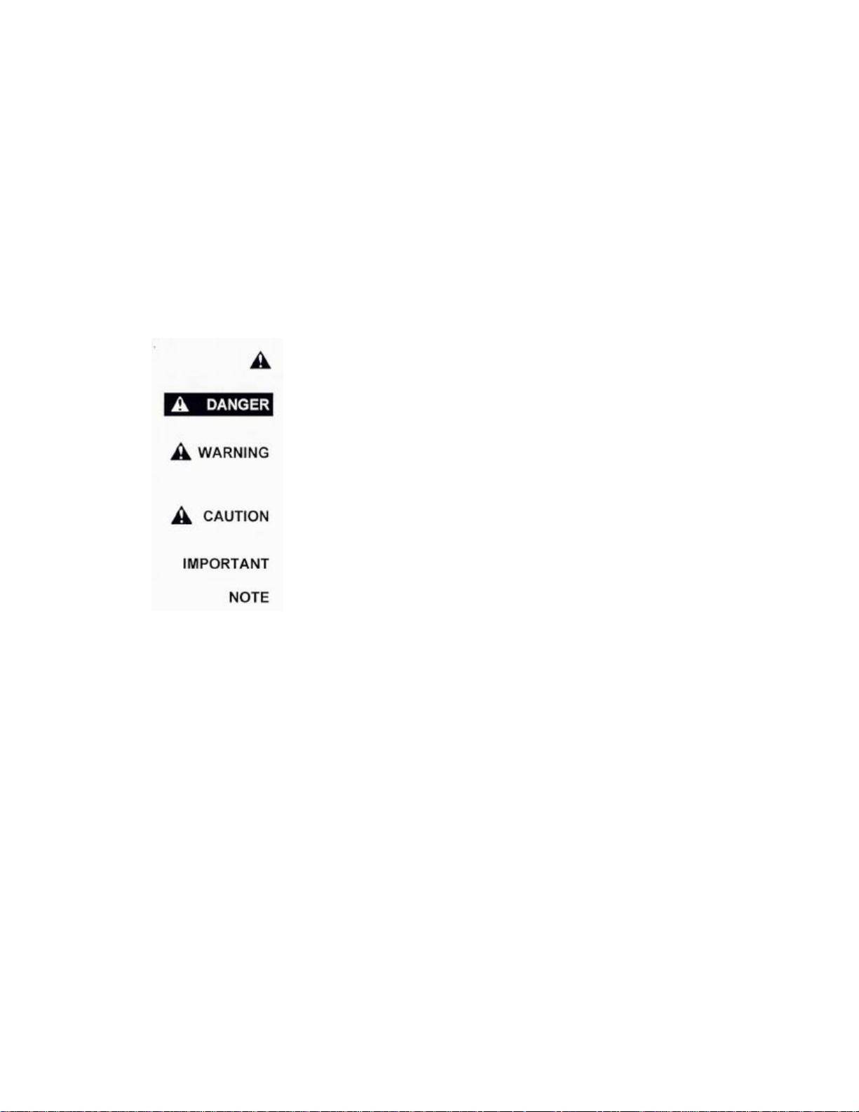
Throughout this manual, the term IMPORTANT is used to indicate that failure to observe can cause
damage to equipment. The terms CAUTION, WARNING and DANGER are used in conjunction with the
Safety-Alert Symbol, (a triangle with an exclamation mark), to indicate the degree of hazard for items of
personal safety. When you see this symbol, carefully read the message that follows and be alert to the
possibility of personal injury or death.
This Safety-Alert symbol indicates a hazard and means
ATTENTION! BECOME ALERT! YOUR SAFETY IS INVOLVED!
Indicates an imminently hazardous situation that, if not avoided, will
result in death or serious injury.
Indicates a potentially hazardous situation that, if not avoided, could
result in death or serious injury, and includes hazards that are exposed
when guards are removed.
Indicates a potentially hazardous situation that, if not avoided, may result
in minor or moderate injury.
Indicates that failure to observe can cause damage to equipment.
Indicates helpful information.
Pg. 3
Page 4

GENERAL INFORMATION (continued)
BOLT TORQUE CHART
Always tighten hardware to these values unless a different torque or tightening procedure is listed for a
specific application.
Fasteners must always be replaced with the same grade as specified in the manual parts list.
Always use the proper tool for tightening hardware. SAE for SAE hardware and Metric for metric
hardware.
Make sure fastener threads are clean and you start the thread engagement properly. All torque values
are given to specification used on hardware defined by SAE J1701 & J1701M (Jul 96).
Pg. 4
Page 5

SPECIFICATIONS
A
Specifications Basket Sizes and Layout
Working
Width
12’ 12’ 12’ N/A 2,195 lbs. 6’ 6’
13’ 13’ 12’ N/A 2,310 lbs. 4’ 5’ 4’
14’ 14’ 12’ N/A 2,425 lbs. 5’ 4’ 5’
15’ 15’ 15’ N/A 2,540 lbs. 5’ 5’ 5’
16’ 16’ 15’ N/A 2,655 lbs. 5’ 6’ 5’
Model TF2
17’ 17’ 15’ N/A 2,770 lbs. 6’ 5’ 6’
18’ 18’ 15’ N/A 2,885 lbs. 6’ 6’ 6’
20’ 13’ 5” 12’ 4’ 4,415 lbs. 4’ 6’ 6’ 4’
22’ 13’ 5” 12’ 5’ 4,645 lbs. 5’ 6’ 6’ 5’
23’ 13’ 5” 12’ 5’ 6” 4,760 lbs. 5.5’ 6’ 6’ 5.5’
24’ 13’ 5” 12’ 6’ 4,875 lbs. 6’ 6’ 6’ 6’
25’ 13’ 5” 12’ 6’ 6” 4,990 lbs. 3’ 3.5’ 6’ 6’ 3.5’ 3’
26’ 13’ 5” 12’ 7’ 5,105 lbs. 3.5’ 3.5’ 6’ 6’ 3.5’ 3.5’
27’ 13’ 5” 12’ 7’ 6” 5,220 lbs. 3.5’ 4’ 6’ 6’ 4’ 3.5’
28’ 13’ 5” 12’ 8’ 5,335 lbs. 4’ 4’ 6’ 6’ 4’ 4’
29’ 13’ 5” 12’ 8’ 6” 5,450 lbs. 3.5’ 5’ 6’ 6’ 5’ 3.5’
30’ 13’ 5” 12’ 9’ 5,565 lbs. 4’ 5’ 6’ 6’ 5’ 4’
Model TF212
31’ 13’ 5” 15’ 9’ 6” 5,680 lbs. 3.5’ 6’ 6’ 6’ 6’ 3.5’
32’ 13’ 5” 15’ 10’ 5,795 lbs. 5’ 5’ 6’ 6’ 5’ 5’
33’ 13’ 5” 15’ 10’ 6” 5,910 lbs. 5’ 5.5’ 6’ 6’ 5.5’ 5’
34’ 13’ 5” 15’ 11’ 6,025 lbs. 5.5’ 5.5’ 6’ 6’ 5.5’ 5.5’
35’ 13’ 5” 15’ 11’ 6” 6,140 lbs. 5.5’ 6’ 6’ 6’ 6’ 5.5’
36’ 13’ 5” 15’ 12’ 6,255 lbs. 6’ 6’ 6’ 6’ 6’ 6’
37’ 15’ 5” 15’ 11’ 6,370 lbs. 5’ 6’ 5’ 5’ 5’ 6’ 5’
38’ 15’ 5” 15’ 11’ 6” 6,485 lbs. 5.5’ 6’ 5’ 5’ 5’ 6’ 5.5’
39’ 15’ 5” 15’ 12’ 6,600 lbs. 6’ 6’ 5’ 5’ 5’ 6’ 6’
40’ 15’ 5” 15’ 12’ 6” 6,715 lbs. 3.5’ 4’ 5’ 5’ 5’ 5’ 5’ 4’ 3.5’
41’ 15’ 5” 15’ 13’ 6,830 lbs. 4’ 4’ 5’ 5’ 5’ 5’ 5’ 4’ 4’
42’ 15’ 5” 15’ 13’ 6” 6,945 lbs. 3.5’ 5’ 5’ 5’ 5’ 5’ 5’ 5’ 3.5’
Model TF215
43’ 15’ 5” 15’ 14’ 7,060 lbs. 4’ 5’ 5’ 5’ 5’ 5’ 5’ 5’ 4’
44’ 15’ 5” 15’ 14’ 6” 7,175 lbs. 4’ 5’ 5.5’ 5’ 5’ 5’ 5.5’ 5’ 4’
45’ 15’ 5” 15’ 15’ 7,290 lbs. 5’ 5’ 5’ 5’ 5’ 5’ 5’ 5’ 5’
Transport
Width
Base
Width
Wing
s
Each
pprox.
Weight
Side Wing Base Unit Side Wing
Pg. 5
Page 6

TABLE OF CONTENTS
WARRANTY 2
GENERAL INFORMATION 3
BOLT TORQUE CHART 4
SPECIFICATIONS 5
SAFETY RULES 7
SAFETY SIGNS 8
SET-UP INSTRUCTIONS 9-15
OPERATIONS 16
TRANSPORTING 17
UNHITCHING 17
FIELD ADJUSTMENT 17
STORAGE 18
SERVICE 18
TROUBLESHOOTING 18
PARTS LIST
TONGUE ASSEMBLY 19
BASE ASSEMBLY 20-23
WING ASSEMBLY 24-25
WHEEL ASSEMBLY 26
LIGHT WIRING DIAGRAM 27
HYDRAULIC LINES AND FITTINGS
Models TF212 and TF215 Without Wing Wheels 28-29
Models TF212 and TF215 With Wing Wheels 30-31
Model TF2 32
OPTIONAL WING WHEEL ASSEMBLY 33
OPTIONAL LEVELING BAR HARROW 34-35
SERVICE / MAINTENANCE RECORD 36
Pg. 6
Page 7

SAFETY RULES
ATTENTION! BECOME ALERT! YOUR SAFETY IS INVOLVED!
Safety is a primary concern in the design and manufacture of our products. Unfortunately, our efforts to
provide safe equipment can be erased by an operator’s single careless act. In addition, hazard control
and accident prevention are dependent upon the awareness, concern, judgment, and proper training of
personnel involved in the operation, transport, maintenance and storage of equi pment.
Make certain that the operator(s), prior to operating is instructed in safe and proper use and reviews and
understands the manual(s) pertaining to this machine.
Read this manual before you operate this machine. If you do not understand any part of this manual, or
need more information, contact the manufacturer or your authorized dealer.
SAFETY
Understand that your safety and the safety of other persons is measured by how you service, and operate
this machine. Know the positions and functions of all controls before you try to operate them. Make sure
to check all controls in a safe area before starting your work.
The safety information given in this manual does not replace safety codes, federal, state or local laws.
Make certain your machine has the proper equipment as designated by local laws and regulations.
A frequent cause of personal injury or death is from persons falling off equipment and being run over. Do
not permit persons to ride on this machine.
Travel speeds should be such that complete control and machine stability is maintained at all times.
Where possible, avoid operating near ditches, embankments and holes. Reduce speed when turning,
crossing slopes and rough, slick or muddy surfaces.
Collision of high speed road traffic and slow moving machines can cause personal injury or death. On
roads, use flasher lights according to local laws. Keep slow-moving-vehicle emblem visible. Pull over to
let faster traffic pass.
Never adjust, service, clean, or lubricate running gear until all power is shut off.
Keep all safety shields in place.
Keep hands, feet, hair and clothing away from moving parts while unit is in operation.
Make sure that everyone is clear of equipment before applying power or moving the machine.
Make sure that the implement is fastened securely to the tractor by using the proper hitch pin, clip and
safety chains.
Do NOT exceed speeds in excess of 20 MPH. Also be sure slow moving vehicle emblem is attached to
rear of transport.
Before unhooking the implement from the towing unit, be sure to properly block the wheels to prevent the
implement from moving. Be sure the jack assembly is positioned in the park position and the weight has
been transferred to the jack assembly before unhooking the implement.
Pg. 7
Page 8

SAFETY SIGNS
IMPORTANT: Install new safety signs if the old signs are destroyed, lost, painted over or cannot be read.
When parts are replaced that have safety signs, make sure you install a new sign with each new part.
New signs are available from the manufacturer or your authorized dealer.
DECAL PARTS LIST
Item # Part # Description
1 DW-107 Warning: Keep Lug Nuts Tight
2 DW-128 Warning: Rapidly Rising Tongue
3 DW-129 Warning: Electric Lines
4 DW-105 Warning: High Pressure Fluid
5 DW-126 Warning: Transport Locks
6 DW-127 Warning: Folding Wings
7 RD-1A Reflective Amber Decal
8 RD-1R Reflective Red Decal
9 RD-1O Reflective Orange Decal
10 DI-114M Medium Size J&M Oval
11 DI-125S Small “J&M Manufacturing” Decal
12 DI-TF2 “TF2” Decal
12 DI-TF212 “TF212” Decal
12 DI-TF215 “TF215” Decal
13 DI-130 “Torsion-Flex” Decal
Pg. 8
Page 9
SET-UP INSTRUCTIONS
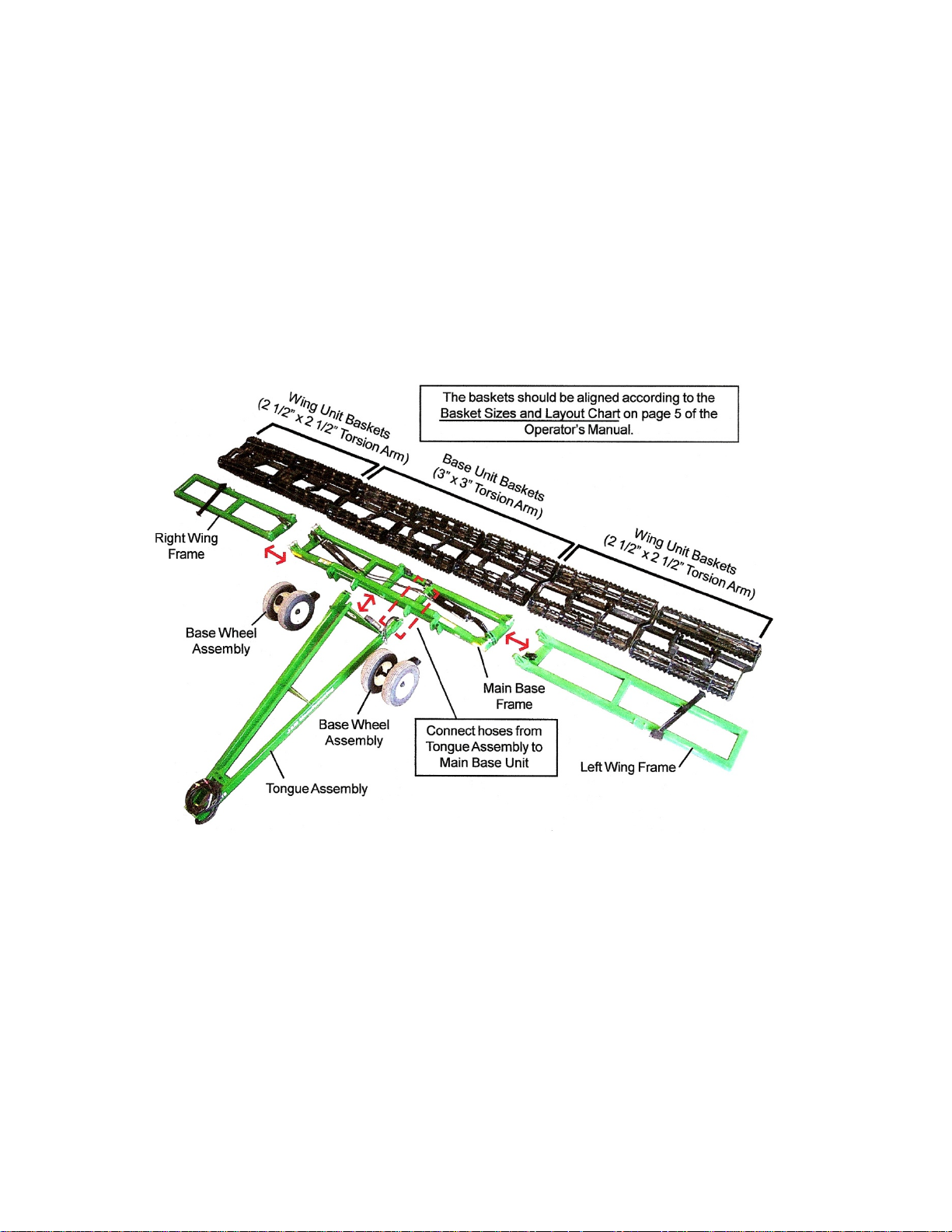
The J&M Torsion-Flex Soil Conditioner is shipped with components partially assembled. Hardware
required to connect the Base Wheel Assembly, Main Base Frame Assembly, Wing Frames and Tongue
Assembly should already be secured to the components at the point of attachment.
The hydraulic cylinders have the fittings already installed and are secured to the base wheel assembly.
The hydraulic hoses and light harness wires should inserted into the component tubing and simply require
the ends to be connected.
Each basket frame should have the rolling baskets and torsion flex arm installed. Refer to the Basket
Size and Layout, located on the right side of the chart on page 5 of the Operator’s Manual for
recommended basket layout. Be sure the baskets with the 3” x 3” Torsion Bars are secure to the Main
Base Unit and the baskets with the smaller 2 1/2” x 2 1/2” Torsion Bars are secured to the side wings.
The optional Lift Assist Bundle (wing wheels) and Harrow are also shipped partially assembled. Refer to
the Set-Up Instructions on the following pages for installation.
Pg. 9
Page 10
SET-UP INSTRUCTIONS
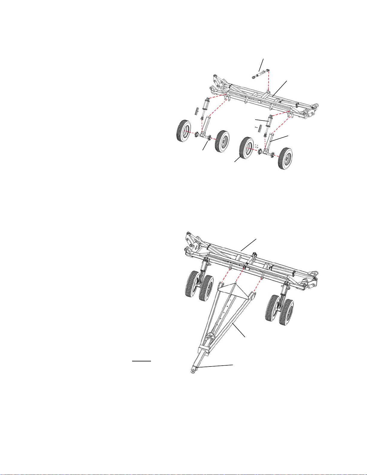
Step 1 – Installing the Base Unit Wheels
Using the 1” x 3 1/2" Pins and cotter pins,
secure the two wheel lift hydraulic cylinders to
the tabs welded on the front of the Base Unit
Main Frame. (NOTE: For implements
equipped with wing wheels, be sure a 3” MS
hydraulic cylinder is used on the right set of
wheels and a 2 3/4" MS hydraulic cylinder is
used for the left set of wheels.)
Hydraulic Cylinder
Bolt the Wheel Arm Weldments to the front of
the Base Unit Main Frame directly below the
hydraulic cylinder shown using one 1 1/4" x 9”
Grade 5 Bolt and 1 1/4" Nylon Lock Nut.
Pin the clevis end of the hydraulic cylinder to
Wheel Hub
Wheel and Tire Assembly
the lower tab on the Wheel Arm Weldment
and secure using the 1” x 3 1/2" pin and cotter pins. Align the wheel and hub and tighten the wheel
nuts in a star pattern to 80 Ft. Lbs. IMPORTANT: Check the w heel nuts periodically to ensure
they remain tight.
Secure one end of the Turn Buckle Assembly to the top of the Base Unit Main Frame as shown using one
1” x 3 1/2" pin and cotter pins.
Step 2 – Installing the A-Frame Tongue
Connect each side arm of the A-Frame
Tongue Assembly to the front of the Main
Frame Base Unit using one 1 1/4" x 6” Grade
5 Bolt and 1 1/4" Hex Nut.
Using the 1” x 3 1/2" pin and cotter pins,
secure the top of the A-Frame Assembly by
connecting the clevis end of the turn buckle to
the end of the upper bar as shown.
Slide the Inner Tongue Weldment into the
tongue A-Frame and secure using the 1” x 8”
Tongue Pin. Insert the 1/2" Hose Holder Rod
into the conduit on the front of the Inner
Tongue Weldment and secure using one 3/8”
x 3/4" Grade 5 Bolt.
Step 3 – Connect the Hydraulic Hoses
For soil conditioners equipped without
wheels, connect the hydraulic hoses and light
wing
Secure 1/2” Hose Holder Rod Here
main wiring harness located in the left side
tubing of the A-Frame to the corresponding
hoses/wires located on the Main Frame Base Unit. For more information, refer to the “Light Kit / Wiring
Harness” and “Hydraulic Hose and Fittings” diagrams at the end of the Set-Up Instructions.
WARNING: Before attaching the cylinders to the wing linkage, charge the cylinders with hydraulic
oil to bleed all air out of the system, and then check for any leaks. Failure to do so could cause
erratic, sudden movement of the wings which could damage the equipment and cause serious
injury or death.
Turn Buckle Assembly
Base Unit Main Frame
Wheel Arm Weldment
Base Unit Main Frame
A-Frame Tongue Assembly
Pg. 10
Page 11
SET-UP INSTRUCTIONS
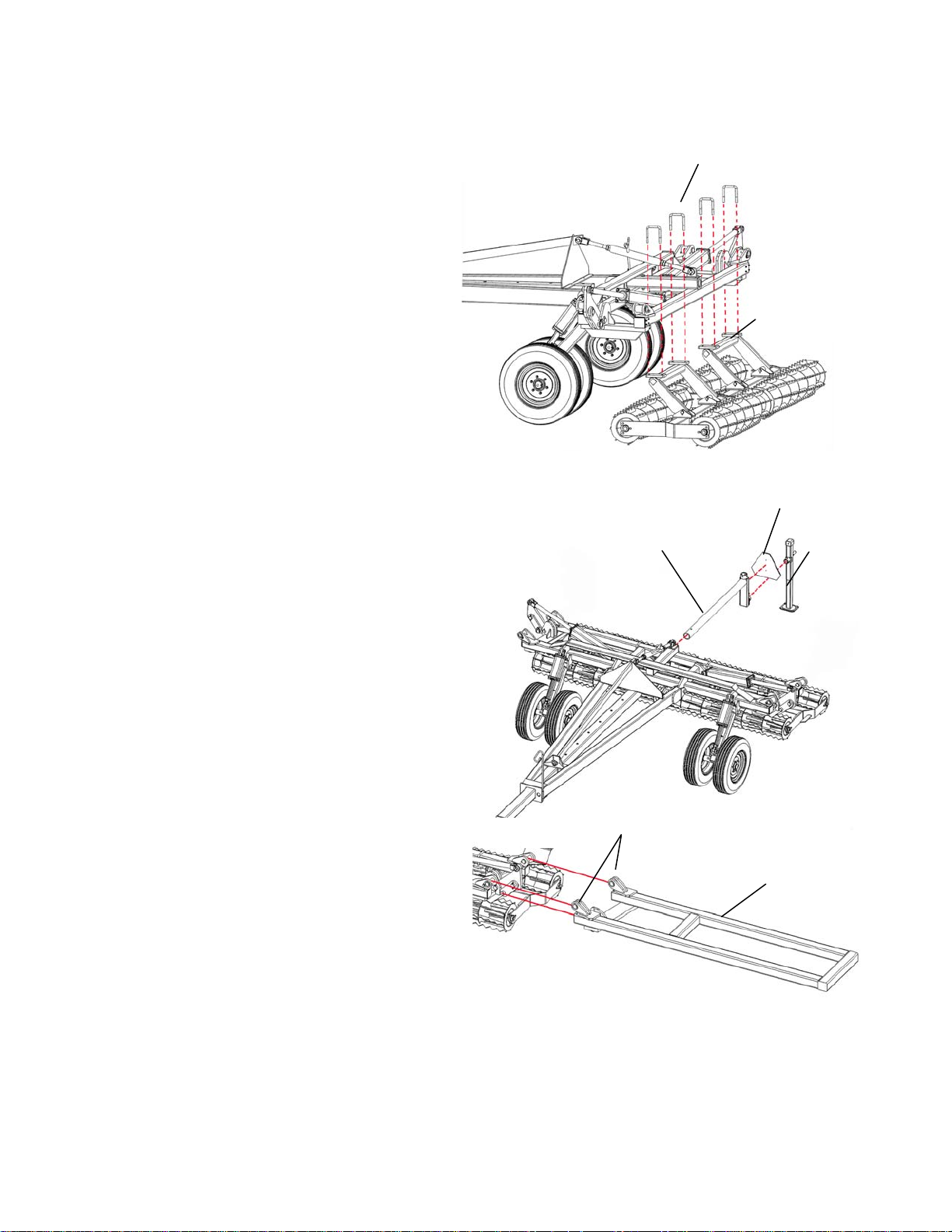
Step 4 – Installing the Base Unit Baskets
Secure the torsion-flex arm of the rolling basket
assembly to the rear tubing member of the Base
Unit Main Frame using two 5/8” x 4” x 5 1/2" UBolts and 5/8” Lock Nuts.
Make sure the baskets are symmetrically
placed on the Base Unit Main Frame and
have a 1 1/2” clearance between baskets.
Note: Be sure the basket assemblies with the 3”
x 3” torsion arms are secured to the Base Unit
Main Frame. The rolling basket assemblies for
the side wings have a smaller 2 1/2” x 2 1/2”
torsion arm.
Step 5 – Installing the Jack Stand
Slide the Storage Extension Arm into the square
tubing on the Base Unit Main Frame as shown
and secure using one 1/2" x 4 1/2" Grade 5 Bolt
and 1/2" Lock Nut. Pin the Jack Stand
Assembly to parking position on the extension
arm and lower the jack so the weight of the base
unit is transferred to the jack. Using two 1/4” x
1” Grade 5 Bolts, mount the SMV emblem to the
extension arm as shown. (Note: For soil
conditioners with side wings that are 5’ long or
smaller. If equipped with side wings longer than
5’, secure the SMV emblem to the right Wing
Arm Rest.
Step 6 – Installing the Wings
Align and connect the hinges on the side Wing
Frame to the matching hinge assembly on the
Main Unit Base Frame using two 1 3/4" x 5 1/4"
Grade 5 Bolt with 1 3/4” Lock Nut.
Connect the Pivot Linkage Arm on the base
main frame to the center tab on the folding wing
frame using one 1 3/4" x 4 3/4” Grade 5 Bolts,
one 1 3/4” Washer and one 7/16” x 2 3/4” Roll
Pin.
5/8” x 4” x 5 1/2” U-Bolts
Rolling Baskets with
3” x 3” Torsion Arm
SMV Emblem
Storage Extension Arm
Align and Secure Corresponding Hinge
Components
Jack Stand
Wing Frame
Pg. 11
Page 12
SET-UP INSTRUCTIONS
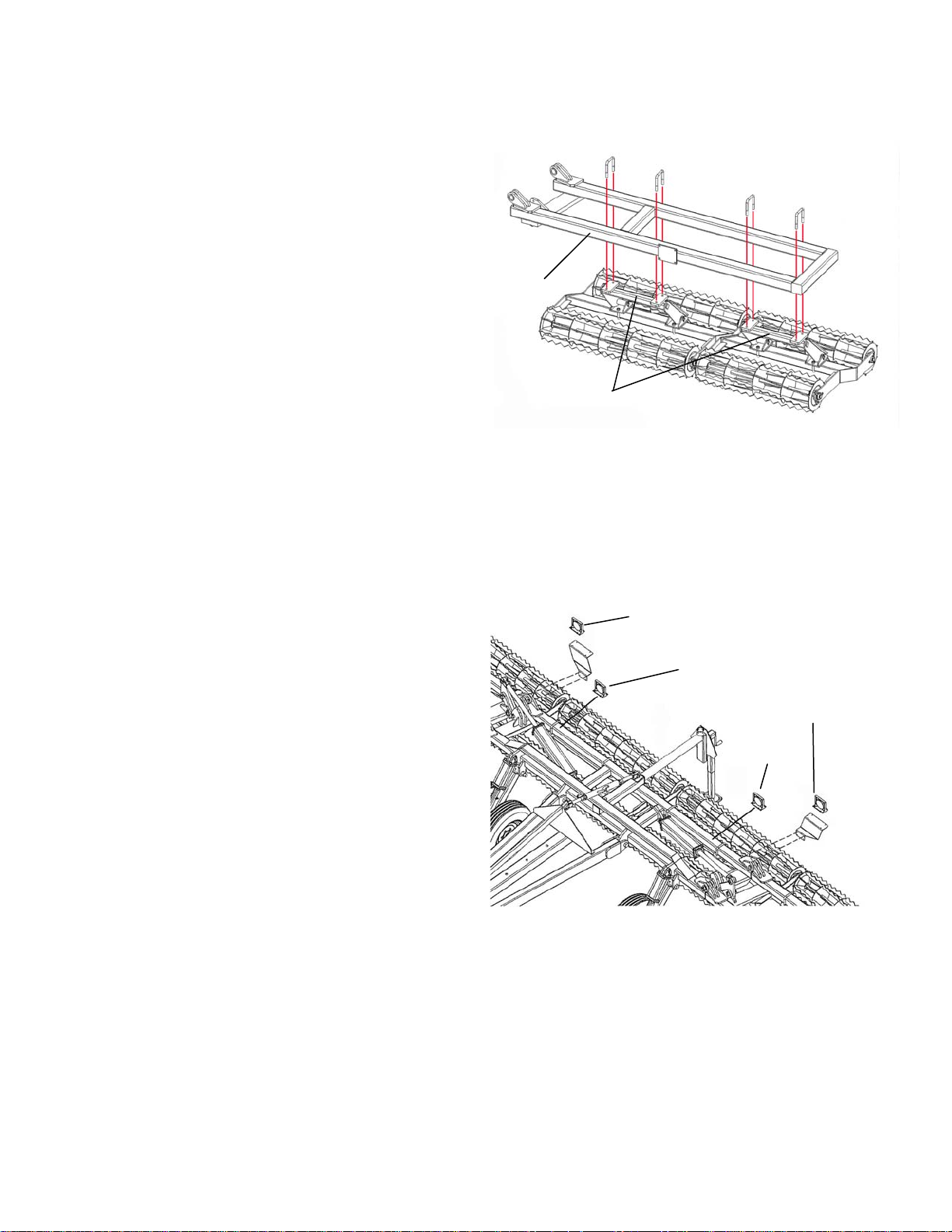
Step 7 – Installing the Wing Baskets
Secure the torsion-flex arm of the rolling basket
assembly to the rear tubing member of the Wing
Frame using two 5/8” x 4” x 5 1/2" U-Bolts and 5/8”
Lock Nuts.
Make sure the wing baskets are placed according to
the “Basket Sizes and Layout” section of the chart
found on page 5. IMPORTANT: Make sure the
wing baskets closest to the baskets on the Base
Unit baskets have a clearance of 2”. The spacing
between wing baskets should have a clearance
of 1 1/2”.
Note: Be sure the basket assemblies with the 2 1/2”
x 2 1/2” x 2’-0” torsion arms are secured to the side
wings. (The baskets on the base unit main frame should have a larger 3” x 3” torsion arm.)
Repeat for opposite side wing.
Step 8 – Installing the Wing Arm Rests
Attach the Wing Rest Arm to the Wing Frame as shown using four 1/2" x 1 1/2" Grade 5 Bolts and 1/2"
Lock Nuts. One wing rest arm is longer than the other. The longer wing arm should be mounted to the
left side wing and the short wing arm should be mounted to the right wing arm.
Step 9 – Mounting the Light Brackets and Lights
Mount the left and right Light Mounting Bracket to
the back of the Base Unit Main Frame using four
1/4” Self-Tapping Screws. Secure the Amber Light
to the mounting bracket using four 1/4” x 1” Grade 5
Bolts and 1/4” Lock Nuts. Place the Red Lights
approximately 18” from the hinges of the Main Base
Unit and secure to the top of the 4” x 4” tubing using
four self-tapping screws.
Snap the end plugs of each light into the light wiring
harness already located inside the frame of the Main
Frame Base Unit.
Front of
Wing
Frame
2 1/2” Torsion Arm
Amber Light
Red Light
Amber Light
Red Light
Pg. 12
Page 13

SET-UP INSTRUCTIONS
INSTALLING OPTIONAL WING WHEELS
For soil conditioners equipped with side wing
wheels, mount the Wing Arm Mount Bracket to the
front tubing member of the Wing Frame as shown
(approximately 6” from the end of the wing frame)
using two 1/2" x 5” Grade 5 Bolts and 1/2" Lock
Nuts.
Bolt the Wheel Arm Weldments to the front of the
Base Unit Main Frame directly below the hydraulic
cylinder shown using one 1 1/4" x 9” Grade 5 Bolt
and 1 1/4" Nylon Lock Nut. Pin the clevis end of the
hydraulic cylinder to the lower tab on the Wheel Arm
Weldment and secure using the 1” x 3 1/2" pin and
cotter pins. Align the wheel and hub and tighten the
wheel nuts in a star pattern to 80 Ft. Lbs.
MS Hydraulic
Cylinder
IMPORTANT: Check the wheel nuts periodic ally to
ensure they remain tight.
Wing Arm Weldment
Using the 1” x 3 1/2" Pins and cotter pins, secure the
two wheel lift hydraulic cylinders to the tabs welded
on the front of the Base Unit Main Frame.
NOTE: Soil Conditioners with working widths between 37’ and 39’ have a longer Wing Arm Rest and a
spacer on the hydraulic cylinder that folds the left side wing.
MAKE SURE THE MS CYLINDERS AND HYDRAULIC HOSES ARE MOUNTED ACCORDING TO THE
DIAGRAM ON PAGE 29.
ADJUSTING THE PRESET VALVE ON THE FOLDING WING CYLINDER
Wings wheels installed on the Torsion Flex Soil Conditoner are equipped with a preset valve on each
folding cylinder that allows the wings to fold in sequence (see hydraulic diagram). When folding the wings
for transport, the right side wing should fold first. When unfolding for field use, the left wing should fold
first. Failure to fold/unfold the wings in proper sequence could result in damage to the wings, wheel
assembly or baskets.
The rate at which the wings fold/unfold is dependent on the side
of the wings and the hydraulic pressure supplied by the tractor.
If the wings fold slower than 2 minutes, the preset valve can be
removed and adjusted to increase hydraulic flow (see diagram).
To increase the hydraulic flow through the preset valve, insert an
L-wrench through the nylon bushing located inside the preset
valve and rotate counter-clockwise up to one complete turn
.
(One complete counter-clockwise turn will increase the flow
through the valve up to 100 psi.) IMPORTANT: Be sure to
adjust the preset valve on each folding wing cylinder the same.
If your tractor supplies too much hydraulic pressure with the existing preset valve, causing the wings to hit
during the fold/unfold sequence, please call our Torsion-Flex Service Department at 419-375-2376 for a
free replacement preset valve set for higher hydraulic pressures.
Wing Arm Rest
Wing Arm Mount
Bracket
Pg. 13
Page 14

SET-UP INSTRUCTIONS
ADJUSTING THE PRESET VALVE ON THE FOLDING WING CYLINDER (continued)
NOTE: Be sure the baskets are free from excessive mud, rocks or debris before beginning the
folding/unfolding sequence. Excessive weight could effect the timing of the folding sequence, causing
possible collision.
WARNING: Charge the cylinders with hydraulic oil to bleed all air out of the system, and then
check for any leaks. Failure to do so could cause erratic, sudden movement of the wings which
could damage the equipment and cause serious injury or death. Units that have the gauge wheels
on the wings have a slave hydraulic system that must be “charged” so the cylinder ram extends
first on all four cylinders.
WHEN TWO SETS OF HYDRAULIC PORTS ARE NOT AVAILABLE…
Torsion Flex Soil Conditioners equipped with wing wheels have one set of hoses to fold the
wings and another set of hoses to raise and lower the wheels. When two hydraulic ports are not
available, we suggest teeing the hydraulic hoses that fold the wings into the hydraulic lines that
fold the wings on the front implement. Therefore, the wings of both implements will fold at the
same time.
INSTALLING THE OPTIONAL HARROW BAR
For part identification, refer to the Harrow Parts List
on pages 34-35.
For each harrow section, attach two Harrow Arm
Mounting Brackets (#2) to the rear tubing along the
wing or base unit using two 5/8” x 4” x 5 1/2” U-Bolt
(#3) and four 5/8” lock nuts (#4). Do not tighten, as
the bracket may need to be adjusted.
Attach one 2” x 8 1/4” Chain Plate (#7) on the front
tubing (directly across from the Harrow Arm
Mounting Bracket) using one 5/8” x 4” x 5 1/2” UBolt (#3) and two 5/8” lock nuts (#4). Do not tighten,
as the plate may need to be adjusted.
Connect one 3” x 21” Harrow Arm to each of the rear mounting bracket using one 3/4” x 6” Grade 5 bolt
(#5) and 3/4” lock nut (#6). Connect the Pivot Bracket (#12) to the lower end of each harrow arm using
one 3/4” x 6” grade 5 bolt (#5) and 3/4” lock nut (#6).
Connect one 16” long chain (#9) to the top of each pivot bracket using one 3/8” x 1” flange bolt (#10) and
3/8” flange nut (#11). Slide the top of the chain through the slot in the chain plate and pin in place using
the Clip Pin (#8). Be sure to pin all the chains to the same length to keep the harrow level.
To Install the Round Bar Assembly
Insert the Round Bar Hooks (#14) into the Round Bar Bracket (#13) and secure using the 1/2” x 1/2”
grade 5 bolts (#17), 1/2” x 2 1/4” oversized washers (#18) and 1/2” lock nuts (#16). Be sure all the round
bars are aligned in the same direction. Secure the round bar bracket to the pivot brackets using the 1/2”
x 4” x 4” U-Bolts (#15) and 1/2” lock nuts (#16).
FRONT
REAR
Pg. 14
Page 15

To Install the Coil Tine Spring Assembly
Slide the Coil Tine Springs (#22) around the Coil Tine Pipe (#21) and secure at each hole location using
the 1/2” x 3 1/2” J-Bolt (#23) and 1/2” Lock Nut (#16). Repeat for each pipe. Secure the Coil Tine Pipe to
the pivot brackets on the lower end of the harrow arm using the two Squeeze Blocks (#19) and four 1/2” x
4 1/2” Grade 5 Bolt (#20) with 1/2” Lock Nuts (#16).
Below is a recommended layout of the harrow pipe bar and round bar bracket lengths along the
width of the conditioner. Be sure the Harrow is properly and evenly spaced along the Base Unit
Main Frame and Wing Frames, making adjustments as necessary.
Coil Tine Pipe Bar and Round Bar Bracket Layout
for Optional Leveling Harrow
Working
Width
12’ 6’ 6’
13’ 4’ 5’ 4’
14’ 5’ 4’ 5’
15’ 5’ 5’ 5’
16’ 5’ 6’ 5’
Model TF2
17’ 6’ 5’ 6’
18’ 6’ 6’ 6’
20’ 4’ 6’ 6’ 4’
22’ 5’ 6’ 6’ 5’
23’ 5’ 6’ 6’ 5’
24’ 6’ 6’ 6’ 6’
25’ 6’ 6’ 6’ 6’
26’ 7’ 6’ 6’ 7’
27’ 7’ 6’ 6’ 7’
28’ 4’ 4’ 6’ 6’ 4’ 4’
29’ 4’ 4’ 6’ 6’ 4’ 4’
30’ 4’ 5’ 6’ 6’ 5’ 4’
Model TF212
31’ 4’ 5’ 6’ 6’ 5’ 4’
32’ 5’ 5’ 6’ 6’ 5’ 5’
33’ 5’ 5’ 6’ 6’ 5’ 5’
34’ 5’ 6’ 6’ 6’ 6’ 5’
35’ 5’ 6’ 6’ 6’ 5’ 6’
36’ 6’ 6’ 6’ 6’ 6’ 6’
37’ 5’ 6’ 5’ 5’ 5’ 6’ 5’
38’ 5’ 6’ 5’ 5’ 5’ 6’ 5’
39’ 6’ 6’ 5’ 5’ 5’ 6’ 6’
40’ 7’ 5’ 5’ 5’ 5’ 5’ 7’
41’ 4’ 4’ 5’ 5’ 5’ 5’ 5’ 4’ 4’
42’ 4’ 4’ 5’ 5’ 5’ 5’ 5’ 4’ 4’
Model TF215
43’ 4’ 5’ 5’ 5’ 5’ 5’ 5’ 5’ 4’
44’ 4’ 5’ 5’ 5’ 5’ 5’ 5’ 5’ 4’
45’ 5’ 5’ 5’ 5’ 5’ 5’ 5’ 5’ 5’
Wing Base Unit Wing
Pg. 15
Page 16

OPERATIONS
PREPARING THE TORSION-FLEX SOIL CONDITIONER
Before putting the soil conditioner into operation, check the machine for damaged or worn parts and
replace as necessary.
Hardware
Make sure all hardware is properly fastened according to the Bolt Torque chart found in this manual.
Recheck all hardware for tightness after the unit has been operated for several hours. Check all pins and
retaining rings are in good condition. Replace any pins of retaining rings that are worn, damaged or
missing.
Hydraulic Hoses
Check all the hydraulic hoses to make sure there are not rubbing against sharp edges or are kinked or
twisted. Hoses should be secured to the soil conditioner with nylon tie straps. Check hoses and fitting for
hydraulic leaks. Tighten or replace as necessary.
Lubrication
Lubricate the Torsion-Flex soil conditioner according to the Lubrication Schedule outlined in the SERVICE
section of this manual.
Tires and Wheels
Check the tire pressure in the transport tires. The recommended air pressure is 46 PSI. Make sure the
tire pressure is equal in all tires. Make sure the wheel lug nuts are tightened to 80 Ft. Lbs. Check the
wheel lug nuts before initial operation and after the unit has been operated for several hours to ensure the
lug nuts remain tight.
Adjusting the Inner Tongue
Before attaching the Torsion-Flex soil conditioner to your primary tillage tool, extend the inner tongue of
the A-Frame Tongue Assembly to ensure adequate turning clearance between the implements when
turning. Adjust the Inner Tongue length by removing the 1” x 8” Tongue Pin and Cotter Pin. Readjust the
Inner Tongue to the appropriate setting and re-pin as before.
Attaching to the Primary Tillage Tool
Back the primary tillage tool into position and attach the soil conditioner to the implement using a high
quality hitch pin and clip and lock into place. Install a transport chain. Transport chain should have a
minimum rating equal to the gross weight of implement and all attachments. Use only ASAE approved
chains. If the unit is parked in the transport position, turn the handle on the jack stand after the soil
conditioner has been connected to the primary tillage tool to remove pressure. Remove the Jack
Assembly from the storage position and re-pin to the transport position located on top of the Storage
Extension Arm.
Unfolding the Wings / Removing the Transport Locks
It is recommended to unfold the side wings in the field. Remove the wheel lift cylinder transport locks so
the unit may be lowered to the field working position. Pin the transport locks on the back of the A-Frame
Tongue Assembly for easy storage.
Pg. 16
Page 17

TRANSPORTING
Before the soil conditioner is transported, be sure to secure the Jack Assembly in the transport position
located on the top of the Storage Extension Arm.
The Torsion-Flex Soil Conditioner will increase the overall length of the primary tillage tool. Use extreme
caution when turning to avoid obstacles. Reduce ground speed as necessary to maintain control of
equipment.
Install hydraulic cylinder transport locks on the Base
Unit wheels BEFORE transporting.
Comply with ALL state and local laws governing
highway safety and regulations when moving
machinery on public roads. Be sure an SMV emblem
is in place and clearly visible on the rear of the
conditioner. Make sure all lights are clearly visible
and working properly BEFORE highway travel. Be
sure the amber, red and orange retroreflective tape on
the implement is in place and clearly visible.
The transport speed should not exceed 10 MPH in the
field or over rough terrain. Reduce transport speed
when necessary to maintain full control of the
implement at all times.
Transport
Cylinder Lock
UNHITCHING
WARNING – Before unhooking the soil conditioner, be sure to install the hydraulic cylinder transport
locks. Reposition the jack stand on the Storage Extension Arm to the parked position and lower the jack
stand to the ground by turning the handle until weight of the soil conditioner is transferred to the jack.
Keep hands and feet away from the jack stand when lowering.
Remove the Hitch Pin and unhook the safety chains.
WARNING – Always relieve hydraulic system pressure before disconnecting hoses from tractor or
servicing hydraulic system. See the tractor’s operators manual for proper procedures. Disconnect the
hydraulic hoses. Install dust covers over the hose plugs and outlets.
FIELD ADJUSTMENTS
The Torsion-Flex Soil Conditioner is designed to provide an excellent seedbed when used in conjunction
with you primary tillage tool. For maximum performance in normal field conditions, the soil conditioner
should be used with the transport wheels in the raised position to allow maximum transfer of weight to the
rolling baskets.
With the wheels in the raised position, adjust the Turn Buckle Adjustment Bar until the wheels are
approximately 2” above the ground. This will set your Torsion-Flex Soil Conditioner at the maximum
clearance height during transport.
The Spring Coil-Tine Harrow Bar is designed to improve the soil leveling capabilities of your conditioner.
To improve the ground leveling capabilities of the harrow in heavier soils, pin the harrow bar so the coiltines are positioned more vertically. In softer soils or to improve field residue flow through the leveler bar,
position the bar with a decreased vertical angle of the tines.
Pg. 17
Page 18

STORAGE
To add longer service and life to your Torsion-Flex Soil Conditioner, perform the following before placing
the implement in storage:
1. Remove dirt and trash that may cause rusting.
2. Repaint any areas where the paint has been chipped, scratched or worn away.
3. Coat all earth moving surfaces with a suitable rust preventative.
4. Inspect for damaged or worn parts and replace before next use.
5. Lubricate wing and wheel pivot points.
6. Block up the conditioner to keep the wheels and ground tools off the ground.
7. Replace all worn, torn and faded decals and reflectors.
8. Store the implement inside away from inclement weather.
SERVICE
To add longer life to your Torsion-Flex Soil Conditioner, perform the following on a regular basis:
1. Grease hinge, linkage area and wheel transport pivots
(3X) weekly or every 40 hours. Grease the 4-Hole Flange
Bearings (1X) on the Rolling Basket Assembly every
50 Hours.
2. Check lighting before over the road transport. Make
sure lights and SMV emblem are clean
from dirt and field debris.
3. Check implement for damage, cracked welds, loosened
hardware, etc. Promptly repair to prevent further damage.
4. Check hydraulic system for leaks and hose damage, twists
or kinks and repair.
5. Check tire pressures and lug nuts periodically and adjust as
required.
TROUBLESHOOTING
When Hydraulics Are Not Functioning Properly…
PROBABLE CAUSE CORRECTION
Hoses are incorrectly connected to the tractor control
levers.
Insufficient hydraulic pressure from Tractor. Check the hydraulic reservoir oil level. See the tractor
Hydraulic components leaking oil. Locate the leak and replace or repair components.
Hydraulic hoses are kinked or twisted. Locate the twisted hose and correct.
Hydraulic cylinders are leaking. Repair or replace cylinders. See Repair Parts section for
The orifice in the wing-fold cylinder is plugged. Remove the contamination from the system. Flush
See the Tractor Operator’s Manual for valve and control
lever arrangement.
Operator’s Manual for hydraulic system
recommendations.
cylinder or seal kit part numbers.
system and change the oil and filter.
Pg. 18
Page 19

TORSION-FLEX SOIL CONDITIONER PARTS LIST
Tongue Assembly
PARTS LIST
Item # Part # Description
1 AFTW-2 A-Frame Tongue Weldment (TF2)
1 AFTW-212 A-Frame Tongue Weldment (T F212)
1 AFTW-215 A-Frame Tongue Weldment (T F215)
2 ITW-TF1 Inner Tongue Weldment
3 12HHR 1/2” Hose Holder Rod
4 3834G5B 3/8” x 3/4" Grade 5 Bolt
5 18PCP 1” x 8” Tongue Pin
6 CP-316 Cotter Pin
7 1146G5B 1 1/4" x 6” Grade 5 Bolt
8 HLN-114 1 1/4" Hex Nut
Pg. 19
Page 20

TORSION-FLEX SOIL CONDITIONER PARTS LIST
Base Assembly
Pg. 20
Page 21

TORSION-FLEX SOIL CONDITIONER PARTS LIST
Base Assembly
PARTS LIST
Item # Part # Descrip tio n
1 BMF-2-12 Base Unit Main Frame (TF2 – 12’ or 13’ working width)
1 BMF-2-14 Base Unit Main Frame (TF2 – 14’ or 15’ working width)
1 BMF-2-16 Base Unit Main Frame (TF2 – 16’ or 17’ working width)
1 BMF-2-18 Base Unit Main Frame (TF2 – 18’ working width)
1 BMF-212 Base Un it Main Frame (TF212)
1 BMF-215 Base Un it Main Frame (TF215)
2 WAW-1 Wheel Arm Weldment (TF2)
2 WAW-2 Wheel Arm Weldme nt (TF212 or TF215)
3 38HC 3” x 8” Hydraulic Cylinder (left or right side wheel cylinder on
units equipped WITHOUT wing wheels)
3 3148HCMS 3 1/4” x 8” MS Hydraulic Cylinder (for units equipped WITH wing
wheels) (32TP08-125 639706)
3 3128HCMS 3 1/2" x 8” MS Hydraulic Cylinder (for units equipped W ITH wing
wheels) (35TP08-125 639707)
4 1149G5B 1 1/4" x 9” Grade 5 Bolt
5 114NLN 1 1/4" Nylon Lock Nut
6 1312P 1” x 3 1/2" Pin
7 CP-316 3/16” Cotter Pin
8 CYLK-2 Cylinder Lock
9 38212WLP 3/8” x 2 1/2" Wire Lock Pin
10 21220TFA 2 1/2” x 2 1/2” x 2’ 0” Torsion-Flex Arm (units under 25’ wide)
10 3330TFA 3” x 3” x 3’ 0” Torsion-Flex Arm (TF212 units 25’ to 36’ wide)
10 3320TFA 3” x 3” x 2’-0” Torsion-Flex Arm (TF215)
11 SWB-1 Swivel Bracket
12 16G5B 1” x 6" Grade 5 Bolt
13 1G5LN 1” Grade 5 Lock Nut
14 584512UB 5/8” x 4” x 5 1/2" U-Bolt
15 5844UB 5/8” x 4” x 4” U-Bolt
16 58G5LN 5/8” Grade 5 Lock Nut
17 12312G5B 1/2" x 3 1/2" Grade 5 Bolt
18 12G5LN 1/2" Grade 5 Lock Nut
19 134514G5B 1 3/4" x 5 1/4" Grade 5 Bolt
20 HN-134 1 3/4” Hex Nut
22 LA-2TF24 Leverage Arm (round hole) (for working widths 24’ and smaller)
22 LA-2TF212 Leverage Arm (oblong hole) (for model TF212, 25’ to 36’ wide)
22 LA-2TF215 Leverage Arm (for model TF215)
23 PLA-2 Pivot Linkag e Arm (TF212)
23 PLA-2L Pivot Linkage Arm, Long (TF215)
24 1344P 1 3/4" x 4” Pin
25 716234RP 7/16” x 2 3/4" Roll Pin
26 424HC 4” x 24” Hydraulic Cylinder (TF212)
26 430HC 4” x 30” Hydraulic Cylinder (TF215)
Pg. 21
Page 22

TORSION-FLEX SOIL CONDITIONER PARTS LIST
Base Assembly (continued)
PARTS LIST
Item # Part # Description
27 TBCB-1 Turn Buckle Center Pipe
28 TBS-2RH Turn Buckle Shaft (both ends R/H thread)
28 TBS-1RH1LH Turn Buckle Shaft (1 end L/H thread; 1 end R/H thread)
29 HN-114 1 1/4" Hex Nut
30 CE-2 Turn Buckle Clevis End
31 TBW-1 Turn Buckle Wrench
32 LP-1 Lynch Pin
33 SEA-1 Storage Extension Arm
34 12412G5B 1/2" x 4 1/2" Grade 5 Bolt
35 JSA-TF Jack Stand Assembly
36 JSA-P1 Jack Stand Assembly Pin
37 LMB-TF-R Light Mounting Bracket (for Right Hand Light)
38 LMB-TF-L Light Mounting Bracket (for Left Hand Light)
39 14STS 1/4” Self Tapping Screw
40 AL-TF1 Single Amber Light
42 141G5B 1/4" x 1” Grade 5 Bolt
43 14LN 1/4" Lock Nut
44 SMV-2 Slow Moving Vehicle Emblem
45 BFS40-4 4’ Basket Frame Support Only (used with soil conditioners
equipped with 4-hole flange bearings)
45 BFS50-4 5’ Basket Frame Support Only (used with soil conditioners
equipped with 4-hole flange bearings)
45 BFS60-4 6’ Basket Frame Support Only (used with soil conditioners
equipped with 4-hole flange bearings)
46 RB40-4-114 4’ Rolling Basket Only (used with soil conditioners equipped with 4-
hole flange bearings with 1 1/4” diameter shaft)
46 RB50-4-114 5’ Rolling Basket Only (used with soil conditioners equipped with 4-
hole flange bearings with 1 1/4” diameter shaft)
46 RB60-4-114 6’ Rolling Basket Only (used with soil conditioners equipped with 4-
hole flange bearings with 1 1/4” diameter shaft)
47 ST491A-162-
114
48 12214G5B 1/2” x 2 1/4” Grade 5 Bolt
49 RL-TF1 Red Flashing L ight
50 1610BL Grease Fitting (not shown)
51 1633 Grease Fitting (not sho wn)
52 SK-3HC Seal Kit for 3” Hydraulic Cylinder (38HC) (SK-3HC)
53 SK639581 Seal Kit for 4” Hydraulic Cylinder (424HC)
54 SK639582 Seal Kit for 4” Hydraulic Cylinder (430HC)
55 FBSS-1 Set Screw in Flange Bearing
56 SK639558 Seal Kit for 3” M/S Hydraulic Cylinder
57 SK639560 Seal Kit for 3 1/4” M/S Hydraulic Cylinder
58 SK639561 Seal Kit for 3 1/2” M/S Hydraulic Cylinder
59 SK639563 Seal Kit for 3 3/4” M/S Hydraulic Cylinder
60 HCSS-1 Set Screw in Hydraulic Cylinder Clevis
1 1/4” Flange Bearing – 4 Hole (used on all soil conditioners with
serial numbers 2250 and higher)
Pg. 22
Page 23

TORSION-FLEX SOIL CONDITIONER PARTS LIST
Base Assembly (continued)
PARTS LIST
Item # Part # Description
62 LW-114 1 1/4” Lock Washer
63 121PS 1/2” x 1” Pipe Spacer
TORSION-FLEX SOIL CONDITIONER PARTS LIST
Wing Assembly
Pg. 23
Page 24

TORSION-FLEX SOIL CONDITIONER PARTS LIST
Left and Right Side Wing Assemblies (TF212 and TF215 only)
PARTS LIST
Item # Part # Descrip tio n
1 WF-212-4 Wing Frame (TF212) (4’ L)
1 WF-212-5 Wing Frame (TF212) (5’ L)
1 WF-212-6 Wing Frame (TF212) (6’ L)
1 WF-212-7 Wing Frame (TF212) (7’ L)
1 WF-212-8 Wing Frame (TF212) (8’ L)
1 WF-212-9 Wing Frame (TF212) (9’ L)
1 WF-212-10 Wing Frame (TF212) (10’ L)
1 WF-212-11 Wing Frame (TF212) (11’ L)
1 WF-212-12 Wing Frame (TF212) (12’ L)
1 WF-215-11 Wing Frame (TF215) (11’ L)
1 WF-215-12 Wing Frame (TF215) (12’ L)
1 WF-215-13 Wing Frame (TF215) (13’ L)
1 WF-215-14 Wing Frame (TF215) (14’ L)
1 WF-215-15 Wing Frame (TF215) (15’ L)
2 WRA-1L Wing Rest Arm (for Left Hand Side Wing)
2 WRA-1R Wing Rest Arm (for Right Hand Side Wing)
3 12112G5B 1/2" x 1 1/2" Grade 5 Bolt
4 12LN 1/2" Lock Nut
5 134434G5B 1 3/4" x 4 3/4" Grade 5 Bolt
6 ------ ---------------------7 716234RP 7/16” x 2 3/4” Roll Pin
8 21220TFA 2 1/2” x 2 1/2” x 2’ 0” Torsion Flex Arm
9 SWB-1 Swivel Bracket
10 16G5B 1” x 6” Grade 5 Bolt
11 1G5LN 1” Grade 5 Lock Nut
12 584512UB 5/8” x 4” x 5 1/2" U-Bolt
13 58G5LN 5/8” Grade 5 Lock Nut
14 5844UB 5/8” x 4” x 4” U-Bolt
15 BFS30-4 3’ Basket Frame Support (used on soil conditioners equipped
with 4-hole flange bearings)
15 BFS36-4 3’ 6” Basket Support Frame (used on so il conditioners equipped
with 4-hole flange bearings)
15 BFS40-4 4’ 0” Basket Support Frame (used on so il conditioners equipped
with 4-hole flange bearings)
15 BFS50-4 5’ Basket Support Frame (use d on soil conditioners equipped
with 4-hole flange bearings)
15 BFS56-4 5’ 6” Basket Support Frame (used on so il conditioners equipped
with 4-hole flange bearings)
15 BFS60-4 6’ Basket Support Frame (use d on soil conditioners equipped
with 4-hole flange bearings)
16 RB30-4-114 3’ Rolling Basket (used on soil conditioners equipped with 4-hole
flange bearings with 1 1/4” diameter shaft)
16 RB36-4-114 3’ 6” Rolling Basket (used on soil conditioners equipped with 4-
hole flange bearings with 1 1/4” diameter shaft)
16 RB40-4-114 4’ Rolling Basket (used on soil conditioners equipped with 4-hole
flange bearings with 1 1/4” diameter shaft)
Pg. 24
Page 25

TORSION-FLEX SOIL CONDITIONER PARTS LIST
Left and Right Side Wing Assemblies (TF212 and TF215 only)
PARTS LIST
Item # Part # Descrip tio n
16 RB40-4-114 4’ Rolling Basket (used on soil conditioners equipped with 4-hole
flange bearings with 1 1/4” diameter shaft)
16 RB50-4-114 4’ 6” Rolling Basket (used on soil conditioners equipped with 4-
hole flange bearings with 1 1/4” diameter shaft)
16 RB56-4-114 5’ 6” Rolling Basket (used on soil conditioners equipped with 4-
hole flange bearings with 1 1/4” diameter shaft)
16 RB60-4-114 6’ Rolling Basket (used on soil conditioners equipped with 4-hole
flange bearings with 1 1/4” diameter shaft)
17 ST491A-162-114 1 1/4” Flange Bearing – 4 Hole
18 12214G5B 1/2” x 2 1/4” Grade 5 Bolt
19 1633 Grease Fitting (not shown)
20 HN-114 1 1/4” Hex Nut
21 LW-114 1 1/4” Lock Washer
23 1234PS 1/2” x 34” Pipe Spacer
Pg. 25
Page 26

TORSION-FLEX SOIL CONDITIONER PARTS LIST
Wheel Assembly
PARTS LIST
Item # Part # Descrip tio n
1 SS-134SC 1 3/4" Diameter Spindle
2 CP-316 Cotter Pin
3 103953 Grease Seal
4 104579 Cone (large) 1 04579 or LM-48548
5 104082 Cone (small) 1040 82 or LM-67048
6 104581 Spindle Washer
7 103289 Slotted Spindle Nut
8 105218 Hub with Studs , Nuts and Cups
9 5552 Wheel Nut
10 4187 Wheel Stud
11 103969 Dust Cap
12 1633 Grease Fitting
13 WR-156-6 Wheel Rim, 15” x 6” – 6 hole (WR-SC2)
13 WR-158-6 Wheel Rim, 15” x 8” – 6 hole
14 760-15SL New Tire (7.60-15SL, 8 ply) (for 15x6 wheel)
14 95L-15SL8PR New Tire (9.5L-15SL, 8 ply) (for 15x8 wheel)
104580 Cup (large) 104580 or LM-48510 (not shown)
104081 Cup (small) 104081 or LM-67 010 (not shown)
Pg. 26
Page 27

g
)
TORSION-FLEX SOIL CONDITIONER PARTS LIST
Light Wiring Harness
Amber Light
Red Light
Run Light Harness through tubing at
grommet locations and connect to Amber
and Red Li
Light Enhancer
hts (typical each side
Red Light
Amber Light
Main Wiring
Harness
PARTS LIST
Item # Part # Descrip tio n
1 MWH-TF2 Main Wiring H arness with 7-Prong Connector End
2 LWH-TF2 Light Wiring Harness (from enhancer to red and amber lights)
3 LE-1B Lig ht Enha ncer (connects main wiring harness with rear lights)
GR-134 1 3/4” Rubber Grommet
Pg. 27
Page 28
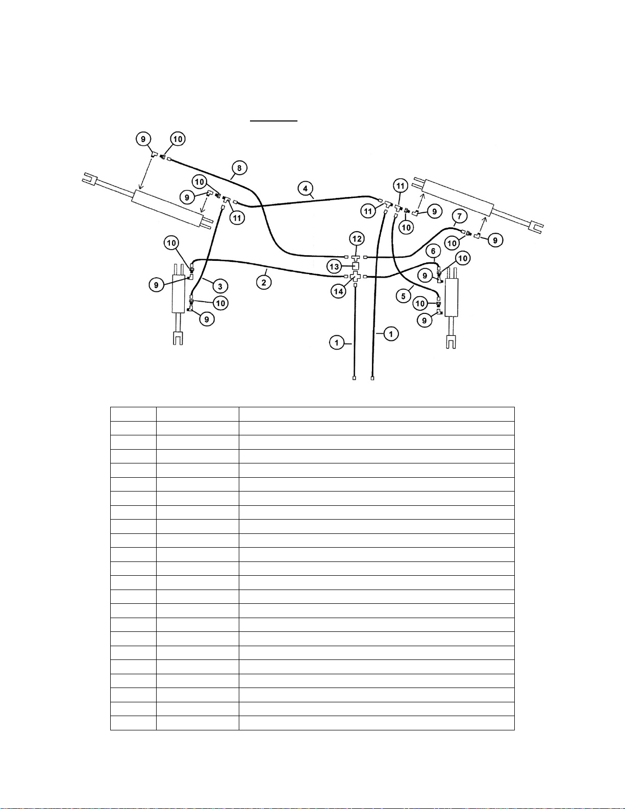
TORSION-FLEX SOIL CONDITIONER PARTS LIST
Hydraulic Lines and Fittings for Models TF212 and TF215
EQUIPPED WITHOUT
OPTIONAL WING WHEELS
PARTS LIST
Item # Part # Descrip tio n
1 HH-38336 3/8” x 336” Hydraulic Hose (TF212)
1 HH-38384 3/8” x 384” Hydraulic Hose (TF215)
2 HH-3866 3/8” x 66” Hydraulic Hose (TF212)
2 HH-3875 3/8” x 75” Hydraulic Hose (TF215)
3 HH-3843 3/8” x 43” Hydraulic Hose (TF212)
3 HH-3832 3/8” x 32” Hydraulic Hose (TF215)
4 HH-3840 3/8” x 40” Hydraulic Hose with swivel end (TF212)
4 HH-3860 3/8” x 60” Hydraulic Hose with swivel end (TF215)
5 HH-3843 38” x 43” Hydraulic Hose (TF212)
5 HH-3832 3/8” x 32” Hydraulic Hose (TF215)
6 HH-3834 3/8” x 34” Hydraulic Hose (TF212)
6 HH-3825 3/8” x 25” Hydraulic Hose (TF215)
7 HH-3829 3/8” x 29” Hydraulic Hose (TF212)
7 HH-3835 3/8” x 35” Hydraulic Hose (TF215)
8 HH-3862 3/8” x 62” Hydraulic Hose (TF212)
8 HH-3888 3/8” x 88” Hydraulic Hose (TF215)
9 12M38F Elbow, 1/2” Male, 3/8” Female
10 1404-045 3/8” Orifice Restrictor (.045)
11 38T-MFF 3/8” T ee (male-female-female)
12 38T-FFM 3/8” Tee (female-female-male)
13 BV-TF1 Ball Valve
14 C1M3F Cross (1 male / 3 female)
Pg. 28
Page 29

TORSION-FLEX SOIL CONDITIONER PARTS LIST
Hydraulic Lines and Fittings for Models TF212 and TF215
EQUIPPED WITH 2-SETS OF HOSES
AND WITHOUT OPTIONAL WING WHEELS
PARTS LIST
Item # Part # Descrip tio n
1 HH-38336 3/8” x 336” Hydraulic Hose (TF212)
1 HH-38384 3/8” x 384” Hydraulic Hose (TF215)
2 HH-3877 3/8” x 77” Hydraulic Hose (TF212)
2 HH-3889 3/8” x 89” Hydraulic Hose (TF215)
3 HH-3865 3/8” x 65” Hydraulic Hose (TF212)
3 HH-3877 3/8” x 77” Hydraulic Hose (TF215)
4 HH-3832 3/8” x 32” Hydraulic Hose (TF212)
4 HH-3844 3/8” x 44” Hydraulic Hose (TF215)
5 HH-3840 3/8” x 40” Hydraulic Hose (TF212)
5 HH-3856 3/8” x 56” Hydraulic Hose (TF215)
6 HH-3862 3/8” x 62” Hydraulic Hose (TF212)
6 HH-3888 3/8” x 88” Hydraulic Hose (TF215)
7 HH-3844 3/8” x 44” Hydraulic Hose (TF212)
7 HH-3860 3/8” x 60” Hydraulic Hose (TF215)
8 HH-3829 3/8” x 29” Hydraulic Hose (TF212)
8 HH-3835 3/8” x 35” Hydraulic Hose (TF215)
9 12M38F Elbow, 1/2” Male, 3/8” Female
10 1404-045 3/8” Orifice Restrictor (.045)
11 38T3F Tee, 3/8” Female (3)
12 38T-FFM 3/8” Tee (female-female-male)
Pg. 29
Page 30

TORSION-FLEX SOIL CONDITIONER PARTS LIST
Hydraulic Lines and Fittings for Model TF212
EQUIPPED WITH OPTIONAL WING WHEELS
PARTS LIST
Item # Part # Descrip tio n
1 HH-12336 1/2” x 336” Hydraulic Hose
2 HH-38210 3/8” x 210” Hydraulic Hose (TF212-32, TF212-33)
2 HH-38222 3/8” x 222” Hydraulic Hose (TF212-34, TF212-35)
2 HH-38234 3/8” x 234” Hydraulic Hose (TF212-36)
3 HH-38174 3/8” x 174” Hydraulic Hose (TF212-32, TF212-33)
3 HH-38186 3/8” x 186” Hydraulic Hose (TF212-34, TF212-35)
3 HH-38198 3/8” x 198” Hydraulic Hose (TF212-36)
4 HH-38162 3/8” x 162” Hydraulic Hose (TF212-32, TF212-33)
4 HH-38174 3/8” x 174” Hydraulic Hose (TF212-34, TF212-35)
4 HH-38186 3/8” x 186” Hydraulic Hose (TF212-36)
5 HH-3862 3/8” x 62” Hydraulic Hose
6 HH-3834 3/8” x 34” Hydraulic Hose
7 HH-3829 3/8” x 29” Hydraulic Hose
8 HH-38112 3/8” x 112” Hydraulic Hose
9 38M38F Elbow, 3/8” Male, 3/8” Female
10 1404-045 3/8” Orifice Restrictor (.045)
11 VBV-1 Valve
12 38T-FFM 3/8” Tee (female-female-male)
13 38M38F-O Elbow, 3/8” Male, 3/8” Female, O-Ring
Pg. 30
Page 31

TORSION-FLEX SOIL CONDITIONER PARTS LIST
Hydraulic Lines and Fittings for Model TF215
EQUIPPED WITH OPTIONAL WING WHEELS
PARTS LIST
Item # Part # Descrip tio n
1 HH-38384 3/8” x 384” Hydraulic Hose
2 HH-38234 3/8” x 234” Hydraulic Hose (TF215-37, TF215-38)
2 HH-38246 3/8” x 246” Hydraulic Hose (TF215-39, TF215-40)
2 HH-38258 3/8” x 258” Hydraulic Hose (TF215-41, TF215-42)
2 HH-38270 3/8” x 270” Hydraulic Hose (TF215-43, TF215-44, TF215-45)
3 HH-38198 3/8” x 198” Hydraulic Hose (TF215-37, TF215-38)
3 HH-38210 3/8” x 210” Hydraulic Hose (TF215-39, TF215-40)
3 HH-38222 3/8” x 222” Hydraulic Hose (TF215-41, TF215-42)
3 HH-38234 3/8” x 234” Hydraulic Hose (TF215-43, TF215-44, TF215-45)
4 HH-38198 3/8” x 198” Hydraulic Hose (TF215-37, TF215-38)
4 HH-38210 3/8” x 210” Hydraulic Hose (TF215-39, TF215-40)
4 HH-38222 3/8” x 222” Hydraulic Hose (TF215-41, TF215-42)
4 HH-38234 3/8” x 234” Hydraulic Hose (TF215-43, TF215-44, TF215-45)
5 HH-3888 3/8” x 88” Hydraulic Hose
6 HH-3854 3/8” x 54” Hydraulic Hose
7 HH-3835 3/8” x 35” Hydraulic Hose
8 HH-38112 3/8” x 112” Hydraulic Hose
9 38M38F Elbow, 3/8” Male, 3/8” Female
10 1404-045 3/8” Orifice Restrictor (.045)
11 VBV-1 Valve
12 38T-FFM 3/8” Tee (female-female-male)
13 38M38F-O Elbow, 3/8” Male, 3/8” Female, O-Ring
Pg. 31
Page 32

TORSION-FLEX SOIL CONDITIONER PARTS LIST
Hydraulic lines and Fittings for Model TF212
EQUIPPED WITH OPTIONAL WING WHEELS
(Since August 2010)
Item#Part#Description
1HH‐38336 1/2"x336"HydraulicHose
2HH‐38210 3/8"x210"HydraulicHose(TF212‐32,TF212‐33)
2HH‐38222 3/8"x222"HydraulicHose(TF212‐34,TF212‐35)
2HH‐38234 3/8"x234"HydraulicHose(TF212‐36)
3HH‐38174 3/8"x174"HydraulicHose(TF212‐32,TF212‐33)
3HH‐38186 3/8"x186HydraulicHose(TF212
‐34,TF212‐35)
3HH‐38198 3/8"x198"HydraulicHose(TF212‐36)
4HH‐38162 3/8"x162"HydraulicHose(TF212‐32,TF212‐33)
4HH‐38174 3/8"x174"HydraulicHose(TF212‐34,TF212‐35)
4HH‐38186 3/8"x186"HydraulicHose(TF212‐36)
5HH‐3862 3/ 8"x62"HydraulicHose
6HH‐3834 3/ 8"x34"HydraulicHose
7HH‐3829 3/ 8"x
29"HydraulicHose
8HH‐38112 3/8"x112"HydraulicHose
9 38M38F Elbow,3/8"Male , 3/8"Female
10 38T‐FFM 3/8"Tee(female‐female‐male)
11 106521 Parke rReliefValvePCK600s‐1.5(SinceAugust2010)
12 106522 Parke rReliefValvePCK600s‐5.0(SinceAugust2010)
13 38M38F‐OElbow,3/8"Male , 3/8"Female,O‐Ring
14 106523 3/8"Mal e 3/8"Male nipple0.62x2.4
15 103524 3/8"Mal e
3/8"FemaleSwiv el0.86x2.4
Pg. 32
Page 33

TORSION-FLEX SOIL CONDITIONER PARTS LIST
Hydraulic Lines and Fittings for Model TF2
(12’ to 18’ Working Width)
PARTS LIST
Item # Part # Descrip tio n
1 HH-38264 3/8” x 264” Hydraulic Hose
2 HH-3877 3/8” x 77” Hydraulic Hose
3 HH-3844 3/8” x 44” Hydraulic Hose
4 HH-3832 3/8” x 32” Hydraulic Hose
5 HH-3865 3/8” x 65” Hydraulic Hose
6 38T3F Tee, 3/8” Female (3)
7 12M38F Elbow, 1/2” Male, 3/8” Female
Pg. 33
Page 34

TORSION-FLEX SOIL CONDITIONER PARTS LIST
Optional Wing Wheel Assembly
PARTS LIST
Item # Part # Descrip tio n
1 WAW-2L Wing Arm Weldment (left)
1 WMB-2R Wing Arm Weldment (right)
2 WMB-2 Wing Arm Mount Bracket
3 125GR5B 1/2" x 5” Grade 5 Bolt
4 12LN 1/2" Lock Nut
5 1149G5B 1 1/4" x 9” Grade 5 Bolt
6 114NLN 1 1/4" Nylon Lock Nut
7 12312G5B 1/2" x 3 1/2" Grade 5 Bolt
8 12G5LN 1/2" Grade 5 Lock Nut
9 3348HCMS 3 3/4” x 8” Hydraulic Cylinder (37TP08-137 639708)
9 38HCMS 3” x 8” Hydraulic Cylinder (30TP08-125 639705)
10 1312P 1” x 3 1/2" Pin
11 CP316 3/16” Cotter Pin
12 1633 Grease Fitting
SK-38HC Seal Kit for Hydraulic Cylinder (not shown)
Pg. 34
Page 35

TORSION-FLEX SOIL CONDITIONER PARTS LIST
Optional Leveling Harrow
REAR
FRONT
Pg. 35
REAR
FRONT
Page 36

TORSION-FLEX SOIL CONDITIONER PARTS LIST
Optional Leveling Harrow
PARTS LIST
# Part # Description # Part # Description
1 321HA 3” x 21” Harrow Arm 14 3415RB 3/4” x 15” Round Bar
2 21246MB 2 1/2” x 4” x 6” Mounting Bracket 15 1244UB 1/2” x 4” x 4” U-Bolt
3 584512UB 5/8” x 4” x 5 1/2” U-Bolt 16 12LN 1/2” Lock Nut
4 58LN 5/8” Lock Nut 17 12112G5B 1/2” x 1 1/2” Grade 5 Bolt
5 346G5B 3/4” x 6” Grade 5 Bolt 18 12214W 1/2” x 2 1/4” O v ersized Washer
6 34LN 3/4” Lock Nut 19 HSB-2 Squeeze Blocks (set)
7 2814CP 2” x 8 1/4” Chain Plate 20 12412G5B 1/2” x 4 1/2” Gr ade 5 Bolt
8 SCP2 Spring Clip Pin 21 CTP38 Coil Tine Pipe x 3’-8” L
9 16RC Chain, 16” L 21 CTP48 Coil Tine Pipe x 4’-8” L
10 381FB 3/8” x 1” Flange Bolt 21 CTP58 Coil Tine Pipe x 5’-8” L
11 38FN 3/8” Flange Nut 21 CTP68 Coil Tine Pipe x 6’-8” L
12 48PB 4” x 8” Pivot Bracket 21 CTP78 Coil Tine Pipe x 7’-8” L
13 RBB40 4’-0” L Round Bar Bracket 22 CTS-1 Coil Tine Spring
13 RBB50 5’-0” L Round Bar Bracket 23 12312JB 1/2” x 3 1/2” J-Bolt
13 RBB60 6’-0” L Round Bar Bracket
13 RBB70 7’-0” L Round Bar Bracket
Pg. 36
Page 37

SERVICE / MAINTENANCE RECORD
Date Description Notes
Pg. 37
 Loading...