

Page 1

TF2
TF212
TF215
Soil Conditioners
OPERATORS MANUAL
Ph: (419) 375-2376 Fax: (419) 375-2708
Rev.3 .21 .2018
J. & M. Mfg. Co., Inc.
284 Railroad Street - P.O. Box 547
Fort Recovery, OH 45846
www.jm-inc.com
Page 2

Table of Contents
To The Dealer 3
General Information 4
Bolt Torque Chart 5
Specications 5
Safety Rules 7
Safety Signs 8
Set-Up Instructions 9-13
Coil Tine Pipe Bar & Round Bar Bracket Layout 14
Operations 15
Transporting, Un-hitching, Field Adjustments 16
Storage, Service, Troubleshooting 17
Parts List 18-32
A-Frame Assembly 18
Main Frame Assembly 19
Outside Wing 20
Wheel Assemblies 21
Torsion Arm 22
Rolling Baskets 23
Coil Tine & Diagonal Bar 24
TF2 Hydraulic Layout 25
TF212-TF215 2 Hoses w/ Lift Assist Hydraulic Layout 26-27
TF212-TF215 4 Hoses w/ Lift Assist Hydraulic Layout 28-29
TF212-TF215 4 Hoses WITHOUT Lift Assist Hydraulic Layout 30
TF212-TF215 2 Hoses WITHOUT Lift Assist Hydraulic Layout 31
Light Harness 32
2
Page 3

To The Dealer
General Information
Read manual instructions and safety rules. Make sure all items on the Dealer’s Pre-Delivery and Delivery Check Lists are completed
before releasing equipment to the owner.
The dealer must complete the Warranty Registration found on the Dealer Portal website located at dealer.jm-inc.com and return
it to J. & M. Mfg. Co., Inc. at the address indicated on the form. Warranty claims will be denied if the Warranty Registration has not been
submitted.
EXPRESS WARRANTY:
J. & M. Mfg. Co. Inc. warrants against defects in construction or materials for a period of ONE year. We reserve the right to inspect
and decide whether material or construction was faulty or whether abuse or accident voids our guarantee.
Warranty service must be performed by a dealer or service center authorized by J. & M. Mfg. Co., Inc. to sell and/or service the type
of product involved, which will use only new or remanufactured parts or components furnished by J. & M. Mfg. Co., Inc. Warranty
service will be performed without charge to the purchaser for parts or labor based on the Warranty Labor Times schedule. Under no
circumstance will allowable labor times extend beyond the maximum hours indicated in the Warranty Labor Times schedule for each
warranty procedure. The purchaser will be responsible, however, for any service call and/or transportation of the product to and
from the dealer or service center’s place of business, for any premium charged for overtime labor requested by the purchaser, and
for any service and/or maintenance not directly related to any defect covered under the warranty. Costs associated with equipment
rental, product down time, or product disposal are not warrantable and will not be accepted under any circumstance.
Each warranty term begins on the date of product delivery to the purchaser. Under no circumstance will warranty be approved
unless (i) the product warranty registration card has been properly completed and submitted to the equipment manufacturer, and
(ii) a warranty authorization number has been issued by the equipment manufacturer. This Warranty is eective only if the warranty
registration card is returned within 30 days of purchase.
This warranty does not cover a component which fails, malfunctions, or is damaged as a result of (i) improper modication or
repair, (ii) accident, abuse or improper use, (iii) improper or insucient maintenance, or (iv) normal wear or tear. This warranty
does not cover products that are previously owned and extends solely to the original purchaser of the product. Should the original
purchaser sell or otherwise transfer this product to a third party, this implied, with respect to tires or other parts or accessories not
manufactured by J. & M. Mfg. Co., Inc. Warranties for these items, if any, are provided separately by their respective manufacturers.
THIS WARRANTY IS EXPRESSLY IN LIEU OF ALL OTHER WARRANTIES OR CONDITIONS, EXPRESS, IMPLIED OR STATUTORY, INCLUDING
ANY IMPLIED WARRANTY OF MERCHANTABILITY OR FITNESS FOR PARTICULAR PURPOSE.
In no event shall J. & M. Mfg. Co., Inc. be liable for special, direct, incidental or consequential damages of any kind. The exclusive
remedy under this Warranty shall be repair or replacement of the defective component at J. & M. Mfg. Co., Inc’s. option. This is the
entire agreement between J. & M. Mfg. Co., Inc. and the Owner about warranty and no J. & M. Mfg. Co., Inc. employee or dealer is
authorized to make any additional warranty on behalf of J. & M. Mfg. Co., Inc.
The manufacturer reserves the right to make product design and material changes at any time without notice. They shall not incur
any obligation or liability to incorporate such changes and improvements in products previously sold to any customer, nor shall
they be obligated or liable for the replacement of previously sold products with products or parts incorporating such changes.
SERVICE:
The equipment you have purchased has been carefully manufactured to provide dependable and satisfactory use. Like all
mechanical products, it will require cleaning and maintenance. Lubricate the unit as specied. Observe all safety information in
this manual and safety signs on the equipment.
For service, your authorized J. & M. dealer has trained mechanics, genuine J. & M. service parts, and the necessary tools and
equipment to handle all your needs.
Use only genuine J. & M. service parts. Substitute parts may void warranty and may not meet standards required for safe and
satisfactory operation. Record the model number and serial number of your equipment in the spaces provided:
Model No:______________ Serial No: ________________________ Date of Purchase: ___________________
Purchased From: ________________________________________________________________________________
Provide this information to your dealer to obtain correct repair parts.
3
Page 4

To The Dealer
General Information
TO THE OWNER:
The purpose of this manual is to assist you in operating and maintaining your soil conditioner in a safe manner. Read it carefully. It
furnishes information and instructions that will help you achieve years of dependable performance and help maintain safe operating
conditions. If this machine is used by an employee or is loaned or rented, make certain that the operator(s), prior to operating:
1. Is instructed in safe and proper use.
2. Reviews and understands the manual(s) pertaining to this machine.
Throughout this manual, the term IMPORTANT is used to indicate that failure to observe can cause damage to equipment. The
terms CAUTION, WARNING and DANGER are used in conjunction with the Safety-Alert Symbol (a triangle with an exclamation mark)
to indicate the degree of hazard for items of personal safety. When you see this symbol, carefully read the message that follows and
be alert to the possibility of personal injury or death.
This Safety-Alert symbol indicates a hazard and means ATTENTION!
BECOME ALERT! YOUR SAFETY IS INVOLVED!
DANGER
WARNING
CAUTION
IMPORTANT
NOTE
Indicates an imminently hazardous situation that, if not avoided, will
result in death or serious injury.
Indicates a potentially hazardous situation that, if not avoided, will
result in death or serious injury, and includes hazards that are exposed
when guards are removed.
Indicates a potentially hazardous situation that, if not avoided, may
result in minor or moderate injury.
Indicates that failure to observe can cause damage to equipment.
Indicates helpful information.
4
Page 5
General InformationBolt Torque Chart
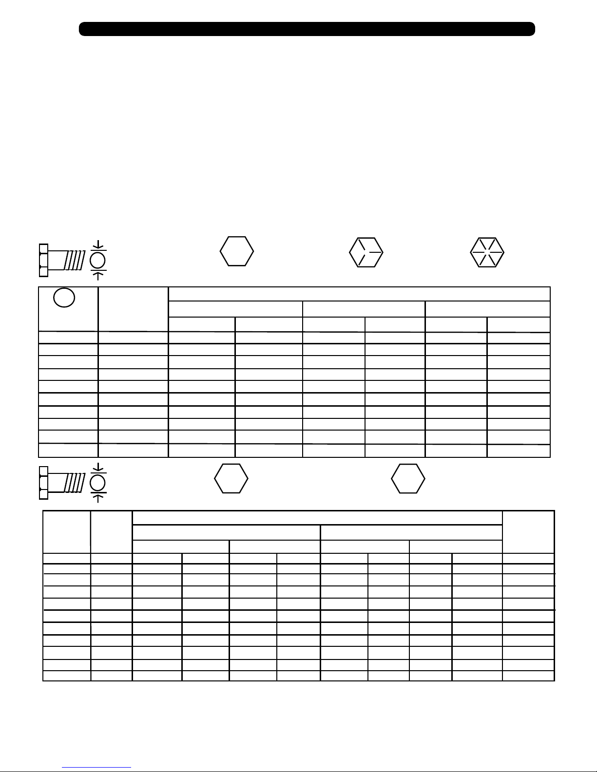
BOLT TORQUE CHART
Always tighten hardware to these values unless a dierent torque or tightening procedure is listed for a specic
application.
Fasteners must always be replaced with the same grade as specied in the manual parts list.
Always use the proper tool for tightening hardware. SAE for SAE hardware and Metric for metric hardware.
Make sure fastener threads are clean and you start the thread engagement properly. All torque values are given
to specication used on hardware dened by SAE J1701 & J1701M (Jul 96).
A
Diameter
(Inches)
1/4
5/16
3/8
7/16
1/2
9/16
5/8
3/4
7/8
1
Diameter
&
(Millimeters)
Thread Pitch
6 x 1.0
8 x 1.25
10 x 1.5
12.1.75
14 x 2.0
16 x 2.0
18 x 2.5
20 x 2.5
22 x 2.5
24 x 3.0
30 x 3.0
SAE SERIES
TORQUE
A
CHART
Wrench
Size
7/16”
1/2”
9/16”
5/8”
3/4”
13/16”
15/16”
1-1/8”
1-5/16”
1-1/2”
METRIC SERIES
TORQUE
A
CHART
Wrench
Size
10 mm
13 mm
16 mm
18 mm
21 mm
24 mm
27 mm
30 mm
34 mm
36 mm
46 mm
109
169
234
330
451
571
1175
SAE Bolt Head
Identication
SAE Grade 2
(No Dashes)
SAE Grade 5
3 Radial Dashes
SAE Grade 8
6 Radial Dashes
MARKING ON HEAD
SAE 2
LBS.-FT.
6
12
23
36
55
78
110
192
306
467
8
17
31
48
75
106
149
261
416
634
8.8
Metric
Grade 8.8
COARSE THREAD FINE THREAD
8
20
39
68
125
172
244
332
421
867
6
15
29
50
80
11
27
54
94
151
234
323
457
623
790
1626
LBS.-FT.
Metric Bolt Head
Identication
8
20
40
70
111
173
239
337
460
583
1199
SAE 5 SAE 8
N-m N-m
10
19
35
55
85
121
170
297
474
722
13
26
47
75
115
164
230
403
642
979
10.9
Metric
Grade 10.9
MARKING ON THREADMARKING ON THREAD
11
29
57
103
163
250
363
507
684
861
1740
21
41
75
118
181
263
367
495
623
1258
8
6
16
30
55
87
133
194
270
365
459
928
Metric 10.9Metric 8.8Metric 8.8 Metric 10.9
LBS.-FT.N-m
1020
14
27
49
78
120
171
240
420
669
22
42
76
120
184
268
374
505
635
1283
18
37
67
106
163
232
325
569
907
1383
Diameter
&
(Millimeters)
Thread Pitch
8
6 x 1.0
8 x 1.0
10 x 1.25
12.1.25
14 x 1.5
16 x 1.5
18 x 1.5
20 x 1.5
22 x 1.5
24 x 2.0
30 x 2.0
5
Page 6

To The DealerSpecications
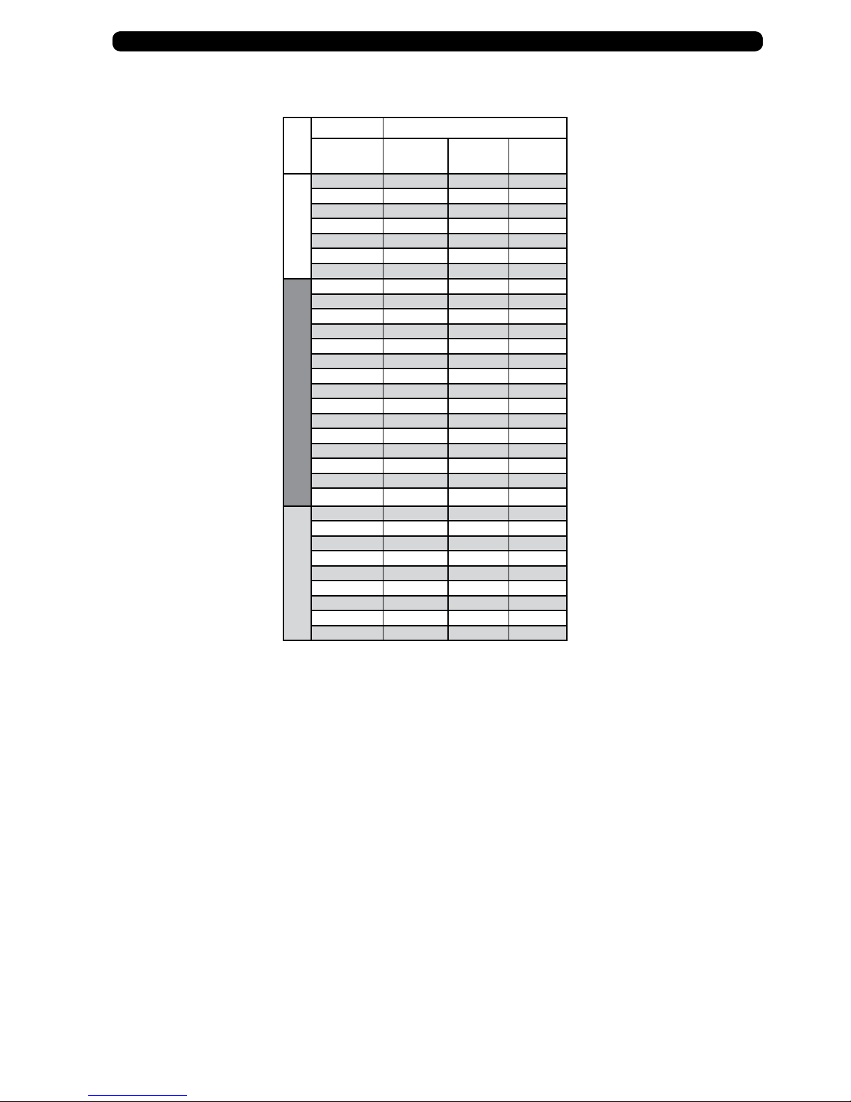
Specications Basket Sizes & Layout
Working
Width
Transport
Width
Base
Width
Wings Each Approx.
Width
Side Wing Base Unit Side Wing
12’ 12’ 12’ N/A 2,195 lbs. 6’ 6’
13’ 13’ 12’ N/A 2,310 lbs. 4’ 5’ 4’
14’ 14’ 12’ N/A 2,425 lbs. 5’ 4’ 5’
15’ 15’ 15’ N/A 2,540 lbs. 5’ 5’ 5’
16’ 16’ 15’ N/A 2,655 lbs. 5’ 6’ 5’
Model TF2
17’ 17’ 15’ N/A 2,770 lbs. 6’ 5’ 6’
18’ 18’ 15’ N/A 2,885 lbs. 6’ 6’ 6’
20’ 13’5” 12’ 4’ 4,415 lbs. 4’ 6’ 6’ 4’
22’ 13’5” 12’ 5’ 4,645 lbs. 5’ 6’ 6’ 5’
23’ 13’5” 12’ 5’6” 4,760 lbs. 5.5’ 6’ 6’ 5.5’
24’ 13’5” 12’ 6’ 4,875 lbs. 6’ 6’ 6’ 6’
26’ 13’5” 12’ 7’ 5,105 lbs. 3.5’ 3.5’ 6’ 6’ 3.5’ 3.5’
27’ 13’5” 12’ 7’6” 5,220 lbs. 3.5’ 4’ 6’ 6’ 4’ 3.5’
28’ 13’5” 12’ 8’ 5,335 lbs. 4’ 4’ 6’ 6’ 4’ 4’
29’ 13’5” 12’ 8’6” 5,450 lbs. 3.5’ 5’ 6’ 6’ 5’ 3.5’
30’ 13’5” 12’ 9’ 5,565 lbs. 4’ 5’ 6’ 6’ 5’ 4’
Model TF212
31’ 13’5” 12’ 9’6” 5,680 lbs. 3.5’ 6’ 6’ 6’ 6’ 3.5’
32’ 13’5” 12’ 10’ 5,795 lbs. 5’ 5’ 6’ 6’ 5’ 5’
33’ 13’5” 12’ 10’6” 5,910 lbs. 5’ 5.5’ 6’ 6’ 5.5’ 5’
34’ 13’5” 12’ 11’ 6,025 lbs. 5.5’ 5.5’ 6’ 6’ 5.5’ 5.5’
35’ 13’5” 12’ 11’6” 6,140 lbs. 5.5’ 6’ 6’ 6’ 6’ 5.5’
36’ 13’5” 15’ 12’ 6,255 lbs. 5 ’ 5.5’ 5’ 5’ 5’ 5.5’ 5’
37’ 15’5” 15’ 11’ 6,370 lbs. 5’ 6’ 6’ 6’ 5’ 5’
38’ 15’5” 15’ 11’6” 6,485 lbs. 5.5’ 6’ 5’ 5’ 5’ 6’ 5.5’
39’ 15’5” 15’ 12’ 6,600 lbs. 6’ 6’ 5’ 5’ 5’ 6’ 6’
40’ 15’5” 15’ 12’6” 6,715 lbs. 3.5’ 5’ 5’ 5’ 5’ 5’ 5’ 4’ 3.5’
41’ 15’5” 15’ 13’ 6,830 lbs. 4’ 5’ 5’ 5’ 5’ 5’ 5’ 4’ 4’
42’ 15’5” 15’ 13’6” 6,945 lbs. 3.5’ 5’ 5’ 5’ 5’ 5’ 5’ 5’ 3.5’
43’ 15’5” 15’ 14’ 7,060 lbs. 4’ 5’ 5’ 5’ 5’ 5’ 5’ 5’ 4’
Model TF215
44’ 15’5” 15’ 14’6” 7,175 lbs. 4’ 5’ 5.5’ 5’ 5’ 5’ 5.5’ 5’ 4’
45’ 15’5” 15’ 15’ 7,290 lbs. 5’ 5’ 5’ 5’ 5’ 5’ 5’ 5’ 5’
6
Page 7

Safety Rules
ATTENTION! BECOME ALERT! YOUR SAFETY IS INVOLVED!
Safety is a primary concern in the design and manufacture of our products. Unfortunately, our eorts to provide safe
equipment can be erased by an operator’s single careless act. In addition, hazard control and accident prevention are
dependent upon the awareness, concern, judgment, and proper training of personnel involved in the operation, transport, maintenance and storage of equipment.
Make certain that the operator(s), prior to operating is instructed in safe and proper use and reviews and understands
the manual(s) pertaining to this machine.
Read this manual before you operate this machine. If you do not understand any part of this manual, or need more
information, contact the manufacturer or your authorized dealer.
SAFETY
Understand that your safety and the safety of other persons is measured by how you service, and operate this machine.
Know the positions and functions of all controls before you try to operate them. Make sure to check all controls in a safe
area before starting your work.
The safety information given in this manual does not replace safety codes, federal, state or local laws. Make certain your
machine has the proper equipment as designated by local laws and regulations.
A frequent cause of personal injury or death is from persons falling o equipment and being run over. Do not permit
persons to ride on this machine.
Travel speeds should be such that complete control and machine stability is maintained at all times. Where possible,
avoid operating near ditches, embankments and holes. Reduce speed when turning, crossing slopes and rough, slick
or muddy surfaces.
Collision of high speed road trac and slow moving machines can cause personal injury or death. On roads, use asher
lights according to local laws. Keep slow-moving-vehicle emblem visible. Pull over to let faster trac pass.
Never adjust, service, clean, or lubricate running gear until all power is shut o.
Keep all safety shields in place.
Keep hands, feet, hair and clothing away from moving parts while unit is in operation.
Make sure that everyone is clear of equipment before applying power or moving the machine.
Make sure that the implement is fastened securely to the tractor by using the proper hitch pin, clip and safety chains.
Do NOT exceed speeds in excess of 20 MPH. Also be sure slow moving vehicle emblem is attached to rear of transport.
Before unhooking the implement from the towing unit, be sure to properly block the wheels to prevent the implement from moving. Be sure the jack assembly is positioned in the park position and the weight has been transferred
to the jack assembly before unhooking the implement.
7
Page 8
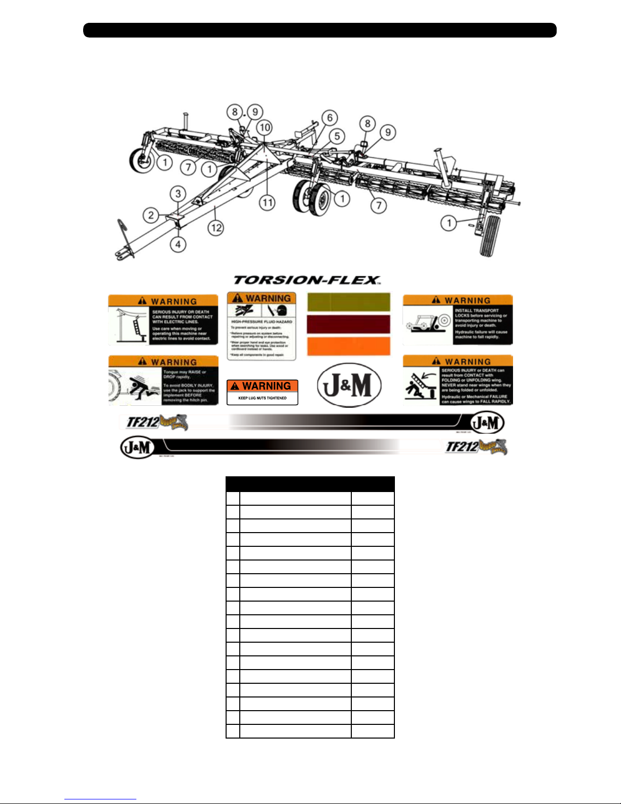
Safety Signs
IMPORTANT: Install new safety signs if the old signs are destroyed, lost, painted over or cannot be read. When parts are replaced that have safety signs,
make sure you install a new sign with each new part. New signs are available from the manufacturer or your authorized dealer.
# Description Part #
1 Warning: Keep Lug Nuts Tight JM0010150
2 Warning: Rapidly Rising Tongue JM0010181
3 Warning: Electric Lines JM0010182
4 Warning: High Pressure Fluid JM0010163
5 Warning: Transport Locks JM0010167
6 Warning: Folding Wings JM0014992
7 Reective Amber Decal JM0009946
8 Reective Red Decal JM0009945
9 Reective Orange Decal JM0009944
10 Medium Size J&M Oval JM0010179
11 Small “J&M Manufacturing” Decal JM0010180
12 “TF2” Decal Driver Side JM0027693
12 “TF2” Decal Passenger Side JM0027688
12 “TF212” Decal Drivers Side JM0027692
12 “TF212” Decal Passenger Side JM0027689
12 “TF215” Decal Drivers Side JM0027691
12 “TF215” Decal Passenger Side JM0027690
13 “Torsion-Flex” Decal JM0010173
8
Page 9

Set-Up Instruction
The J&M Torsion-Flex Soil Conditioner is shipped with components partially assembled. Hardware required to connect the Base Wheel
Assembly, Main Base Frame Assembly, Wing Frames and Tongue Assembly should already be secured to the components at the point of
attachment.
The hydraulic cylinders have the ttings already installed and are secured to the base wheel assembly. The hydraulic hoses and light harness
wires should be inserted into the component tubing and simply require the ends to be connected.
Each basket frame should have the rolling baskets and torsion ex arm installed. Refer to the Basket Size and Layout, located on the right
side of the chart on page 5 of the Operator’s Manual for recommended basket layout. Be sure the baskets with the 3” x 3” Torsion Bars are
secure to the Main Base Unit and the baskets with the smaller 2 1/2” x 2 1/2” Torsion Bars are secured to the side wings.
Optional Li Assist
Wheel Assembly
Wing Unit Baskets
2-1/2” x 2-1/2” Torsion Arm
Right Wing Frame
Base Unit Baskets
3” x 3” Torsion Arm
Base Wheel Assembly
Wing Unit Baskets
2-1/2” x 2-1/2” Torsion Arm
Main Base Frame
Le Wing Frame
Base Wheel Assembly Optional Li Assist
Wheel Assembly
Tongue Assembly
9
Page 10

To The DealerSet-Up Instructions
• Wheel Arm Weldment
Attach the wheel are weldment to the main frame.
Use a 1-1/4” x 9 “ hex bolt and 1-1/4” hex nut.
Tighten hardware.
• Wheel & Tire Assembly
Attach the wheel and tire assembly using (6) 1/2” wheel nuts.
Align the wheel and hub and tighten the wheel nuts in a star
pattern to 80 Ft. Lbs. Check the wheel nuts periodically to
ensure they remain tight.
• Lift Cylinder
Attach the lift cylinder to the main frame using a 1” x 5” hex bolt and a 1” nylon locking
hex nu t. Attach the lift c ylinder to the wheel arm weldment using a 1” x 3-1/2” clevis pin
and (2) cotter pins. Fasten hardware once secured.
Install the cylinder lock, fasten with provided lynch pin.
• Turnbuckle
Secure one end of the turn buckle assembly to the top of the main
frame as shown using one 1” x 3-1/2” clevis pin and cotter pin.
Turnbuckle
Li Cylinder
Wheel Arm Weldment
Cylinder Lock
Wheel & Tire Assembly
• A-Frame Weldment
Connect the A-Frame to the Base Unit.
Use (2) 1-1/4” x 6” hex bolts and (2) 1-1/4” nylon locking hex nuts.
Tongue Pin
Both bolts face the inside of the A-frame. Fasten hardware once secured.
• Turnbuckle
Secure the other end of the turn buckle assembly to the top of the
Hose Holder Rod
A-Frame
A-frame using a 1” x 3-1/2” clevis pin and cotter pin.
• Tongue Weldment
Slide Tongue Weldment inside the A-frame. Secure with 1” x 8” tongue pin.
Attach Hose Holder Rod to the Tongue Weldment.
Fasten with 3/8” x 3/4” hex bolt. Fasten hardware once secured.
Tongue Weldment
• Hydraulic Hoses & Light Harness
Based on your model go to pages 22-28 to nd the destination of each hydraulic
hose. Connect the A-Frame harness to the Main Frame harness. Secure with zip-ties.
WARNING: Before attaching the cylinders to the wing linkage, charge the cylinders with hydraulic oil to bleed all air out of the system, and then check for
any leaks. Failure to do so could cause erratic, sudden movement of the wings which could damage the equipment and cause serious injur y or death.
10
Page 11

General InformationSet-Up Instructions
• Base Unit Baskets
Attach the 3’ Heavy Torsion arms to the rolling basket. Secure with 1” x 6-1/2” hex
bolt and 1” nylon locking hex nut. Fasten hardware once secured.
(Rocker Pads may need installed. Use 4-1/8” x 4-1/2” x 5/8” U-Bolt and (2) 5/8”
nylon locking hex nuts.)
Make sure the baskets are symmetrically placed on the Base Unit Main
Frame and have a 1-1/2” clearance between baskets.
NOTE: Be sure the basket assemblies with the 3” x 3” torsion arms are secured to the
Base Unit Main Frame. The rolling basket assemblies for the side wings have a smaller
2-1/2” x 2-1/2” torsion arm.
• Attach the torsion arm - rolling basket assembly to the main frame. Secure each
torsion arm with (2) 5/8” x 4” x 6” U-bolts and a 5/8” centerlock hex nut.
Fasten hardware once secured.
• Jack Stand
Secure the Jack Stand Weldment to the Main Frame using (5) 1/2” x 1-1/2” hex
bolts and (5) 1/2” centerlock hex nuts. Fasten hardware once secured.
Attach the jack stand to the support arm using the supplied pin.
Torsion Arms
3” x 3”
Rolling Basket
Rocker Pad
5/8” x 4” x 6”
U-Bolts
Jack Stand
1/2” x 1-1/2”
• Wing Frame
Attach the Wing Frames to the Main Frame. For each wing use :
• 1-3/4” x 6-3/8” Welded Pin
• 1-3/4”x 5” Welded Pin
• (2) 1-3/4” Hex Nuts
• 4” Wing Pin
• (4) Roll Pins
Once secured, fasten hardware.
• Wing Rest
Attach a Wing Rest weldment to each wing. Secure using (4) 1/2” x 1-1/4” hex
bolts and (4) 1/2” centerlock hex nuts.
Once secured, fasten hardware.
Jack Stand Weldment
Wing Frame
Wing Rest
1-3/4” x 6-3/8” 4” Wing Pin 1-3/4”x 5”
11
Page 12

To The DealerSet-Up Instructions
• Wing Baskets
Attach the 2’ Light Torsion arms to the rolling basket. Secure with 1” x 6-1/2”
hex bolt and 1” nylon locking hex nut. Fasten hardware once secured.
(Rocker Pads may need installed. Use 4-1/8” x 4-1/2” x 5/8” U-Bolt and (2) 5/8”
nylon locking hex nuts.)
Make sure the wing baskets are placed according to the “Basket Sizes and Layout”
section of the chart found on page 5. IMPORTANT: Make sure the wing baskets
closest to the baskets on the Base Unit baskets have a clearance of 2”. The
spacing between each wing baskets should have a clearance of 1-1/2”.
• Attach each torsion arm - rolling basket assembly to the wing. Secure each
torsion arm with (2) 5/8” x 4” x 6” U-bolts and (4) 5/8” centerlock hex nuts.
Torsion Arms
2-1/2” x 2-1/2”
Rocker Pad
Rolling Basket
5/8” x 4” x 6”
U-Bolts
• Lights and Light Brackets
Secure both Red Lights to the Main Frame using (4) 1/4” self tapping screws for
each light.
Secure both Amber Lights and Light Brackets to the Main Frame using (4) 1/4” x
5/8” hex bolts and (4) 1/4” hex nuts per light.
Connect all lights to the main wiring harness. The main harness is installed and
located inside the frame. All remaining wiring needs to be stored inside the frame.
• Optional Wing Wheels
Secure the Wing Arm Mount Bracket to the Wing. Place bracket approximately 6” from
the outside of the Wing. Secure using (2) 1/2” x 6” hex bolts and (2) 1/2” centerlock hex
nuts. Fasten hardware once secured.
Attach the Wing Arm Weldment to the Mount Bracket. Secure with a 1-1/4” x 10” hex
bolt and 1-1/4” nylon locking hex nut.
Attach the wheel and tire assembly using (6) 1/2” wheel nuts.
Align the wheel and hub and tighten the wheel nuts in a star
pattern to 80 Ft. Lbs. Check the wheel nuts periodically to
ensure they remain tight.
Attach the hydraulic cylinder to the Wing Arm Weldment. Secure with a 1” x 5” hex
bolt, 1” nylon locking hex nut, 1” x 3-1/2” clevis pin, and (2) cotter pins. Fasten
hardware once secure. Install the cylinder lock, fasten with provided lynch pin.
NOTE: See page 22-26 for correct hydraulic cylinder layout.
Wing Arm Mount Bracket
Amber Light
Red Light
1” x 5” Hex Bolt
1-1/4” x 9” Hex Bolt
1/2” x 6” Hex Bolt
Hydraulic Cylinder
Wing Arm Weldment
1” x 3-1/2” Clevis Pin
Tire & Wheel Assembly
12
Page 13

General InformationSet-Up Instructions
• Coil Tine Spring Assembly
For part identication, refer to page 24.
For Coil Tine Spring Assembly layout see page 14.
Attach the Coil Tine Spring Assembly to the main frame or wing weldment.
Secure the Coil Tine Spring Assembly with (2) 1/2” x 4-1/8” x 5” U-bolts and (4) 1/2”
centerlock hex nuts. Fasten hardware once secured.
• Round Bar Assembly
For part identication, refer to page 24.
For Round Bar Assembly layout see page 14.
Attach the Round Bar Assembly to the main frame or wing weldment.
Secure the Round Bar Assembly with (2) 1/2” x 4-1/8” x 5” U-bolts and (4) 1/2”
centerlock hex nuts. Fasten hardware once secured.
1/2” x 4-1/8” x 5” U-Bolt
Coil Tine Spring Assembly
Round Bar Assembly
13
Page 14
To The DealerCoil Tine Pipe Bar & Round Bar Bracket Layout
Below is a recommended layout of the harrow pipe bar and round bar bracket lengths along the width of the conditioner.
Be sure the Harrow is properly and evenly spaced along the Base Unit Main Frame and Wing Frames, making adjustments as
necessary.
Specications Basket Sizes & Layout
Working
Width
12’ 6’ 6’
13’ 4’ 5’ 4’
14’ 5’ 4’ 5’
15’ 5’ 5’ 5’
16’ 5’ 6’ 5’
17’ 6’ 5’ 6’
Model TF2
18’ 6’ 6’ 6’
20’ 4’ 6’ 6’ 4’
22’ 5’ 6’ 6’ 5’
23’ 5’ 6’ 6’ 5’
24’ 6’ 6’ 6’ 6’
26’ 7’ 6’ 6’ 7’
27’ 7’ 6’ 6’ 7’
28’ 4’ 4’ 6’ 6’ 4’ 4’
29’ 4’ 5’ 6’ 6’ 5’ 4’
30’ 4’ 5’ 6’ 6’ 5’ 4’
31’ 4’ 6’ 6’ 6’ 6’ 4’
32’ 5’ 5’ 6’ 6’ 5’ 5’
33’ 5’ 5’ 6’ 6’ 5’ 5’
34’ 5’ 6’ 6’ 6’ 6’ 5’
35’
36’ 6’ 6’ 6’ 6’ 6’ 6’
Model TF 212
37’ 5’ 6 ’ 6’ 6’ 5’ 5’
38’ 5’ 6’ 5’ 5’ 5’ 6’ 5’
39’ 6’ 6’ 5’ 5’ 5’ 6’ 6’
40’ 7’ 5’ 5’ 5’ 5’ 5’ 7’
41’ 4’ 4’ 5’ 5’ 5’ 5’ 5’ 4’ 4’
42’ 4’ 4’ 5’ 5’ 5’ 5’ 5’ 4’ 4’
43’ 4’ 5’ 5’ 5’ 5’ 5’ 5’ 5’ 4’
44’ 4’ 5’ 5’ 5’ 5’ 5’ 5’ 5’ 4’
Model TF215
45’ 5’ 5’ 5’ 5’ 5’ 5’ 5’ 5’ 5’
Side Wing Base Unit Side Wing
5’ 6’
6’ 6’ 6’ 5’
14
Page 15

Operations
PREPARING THE TORSION-FLEX SOIL CONDITIONER
Before putting the soil conditioner into operation, check the machine for damaged or worn parts and replace as necessary.
Hardware
Make sure all hardware is properly fastened according to the Bolt Torque chart found in this manual. Recheck all hardware for tightness after the
unit has been operated for several hours. Check all pins and retaining rings are in good condition. Replace any pins of retaining rings that are worn,
damaged or missing.
Hydraulic Hoses
Check all the hydraulic hoses to make sure there are not rubbing against sharp edges or are kinked or twisted. Hoses should be secured to the soil
conditioner with nylon tie straps. Check hoses and tting for hydraulic leaks. Tighten or replace as necessary.
Lubrication
Lubricate the Torsion-Flex soil conditioner according to the Lubrication Schedule outlined in the SERVICE section of this manual.
Tires and Wheels
Check the tire pressure in the transport tires. The recommended air pressure is 46 PSI. Make sure the tire pressure is equal in all tires. Make sure the
wheel lug nuts are tightened to 80 Ft. Lbs. Check the wheel lug nuts before initial operation and after the unit has been operated for several hours
to ensure the lug nuts remain tight.
Adjusting the Inner Tongue
Before attaching the Torsion-Flex soil conditioner to your primary tillage tool, extend the inner tongue of the A-Frame Tongue Assembly to ensure
adequate turning clearance between the implements when turning. Adjust the Inner Tongue length by removing the 1” x 8” Tongue Pin and Cotter
Pin. Readjust the Inner Tongue to the appropriate setting and re-pin as before.
Attaching to the Primary Tillage Tool
Back the primary tillage tool into position and attach the soil conditioner to the implement using a high quality hitch pin and clip and lock into
place. Install a transport chain. Transport chain should have a minimum rating equal to the gross weight of implement and all attachments. Use
only ASAE approved chains. If the unit is parked in the transport position, turn the handle on the jack stand after the soil conditioner has been
connected to the primary tillage tool to remove pressure. Remove the Jack Assembly from the storage position and re-pin to the transport position
located on top of the Storage Extension Arm.
Unfolding the Wings / Removing the Transport Locks
It is recommended to unfold the side wings in the eld. Remove the wheel lift cylinder transport locks so the unit may be lowered to the eld
working position. Pin the transport locks on the back of the A-Frame Tongue Assembly for easy storage.
15
Page 16

Transporting
Before the soil conditioner is transported, be sure to secure the Jack Assembly in the transport position located on the top of the Storage Extension
Arm.
The Torsion-Flex Soil Conditioner will increase the overall length of the primary tillage tool. Use extreme caution when turning to avoid obstacles.
Reduce ground speed as necessary to maintain control of equipment.
Install hydraulic cylinder transport locks on the Base Unit wheels BEFORE transporting.
Comply with ALL state and local laws governing highway safety and regulations
when moving machinery on public roads. Be sure an SMV emblem is in place and
clearly visible on the rear of the conditioner. Make sure all lights are clearly visible
and working properly BEFORE highway travel. Be sure the amber, red and orange
retroreective tape on the implement is in place and clearly visible.
The transport speed should not exceed 10 MPH in the eld or over rough terrain.
Reduce transport speed when necessary to maintain full control of the implement
at all times.
Unhitching
WARNING – Before unhooking the soil conditioner, be sure to install the hydraulic cylinder transport locks. Reposition the jack stand on the Storage
Extension Arm to the parked position and lower the jack stand to the ground by turning the handle until weight of the soil conditioner is transferred
to the jack. Keep hands and feet away from the jack stand when lowering.
Remove the Hitch Pin and unhook the safety chains.
WARNING – Always relieve hydraulic system pressure before disconnecting hoses from tractor or servicing hydraulic system. See the tractor’s operators manual for proper procedures. Disconnect the hydraulic hoses. Install dust covers over the hose plugs and outlets.
Field Adjustments
The Torsion-Flex Soil Conditioner is designed to provide an excellent seedbed when used in conjunction with you primary tillage tool. For maximum
performance in normal eld conditions, the soil conditioner should be used with the transport wheels in the raised position to allow maximum
transfer of weight to the rolling baskets.
With the wheels in the raised position, adjust the Turn Buckle Adjustment Bar until the wheels are approximately 2” above the ground. This will set
your Torsion-Flex Soil Conditioner at the maximum clearance height during transport.
The Spring Coil-Tine Harrow Bar is designed to improve the soil leveling capabilities of your conditioner. To improve the ground leveling capabilities of
the harrow in heavier soils, pin the harrow bar so the coil-tines are positioned more vertically. In softer soils or to improve eld residue ow through
the leveler bar, position the bar with a decreased vertical angle of the tines.
16
Page 17

Storage
To add longer service and life to your Torsion-Flex Soil Conditioner, perform the following before placing the implement in storage:
1. Remove dirt and trash that may cause rusting.
2. Repaint any areas where the paint has been chipped, scratched or worn away.
3. Coat all earth moving surfaces with a suitable rust preventative.
4. Inspect for damaged or worn parts and replace before next use.
5. Lubricate wing and wheel pivot points.
6. Block up the conditioner to keep the wheels and ground tools o the ground.
7. Replace all worn, torn and faded decals and reectors.
8. Store the implement inside away from inclement weather.
Service
To add longer life to your Torsion-Flex Soil Conditioner, perform the following on a regular basis:
1. Grease hinge, linkage area and wheel transport pivots (3X) weekly or
every 40 hours. Grease the 4-Hole Flange Bearings (1X) on the Rolling
Basket Assembly every 50 Hours.
2. Check lighting before over the road transport. Make sure lights and
SMV emblem are clean from dirt and eld debris.
3. Check implement for damage, cracked welds, loosened hardware,
etc. Promptly repair to prevent further damage.
4. Check hydraulic system for leaks and hose damage, twists or kinks
and make necessary repairs.
Bearings
5. Check tire pressures and lug nuts periodically and adjust as required.
Pivots
NOTE: Basket bearings do not need greased before the rst use. e basket bearings are greased at the factory.
Troubleshooting
When Hydraulics Are Not Functioning Properly...
PROBABLE CAUSE CORRECTION
Hoses are incorrectly connected to the tractor control levers. See the Tractor Operator’s Manual for valve and control lever arrange-
ment.
Insucient hydraulic pressure from Tractor. Check the hydraulic reservoir oil level. See the tractor Operator’s
Manual for hydraulic system recommendations.
Hydraulic components leaking oil. Locate the leak and replace or repair components.
Hydraulic hoses are kinked or twisted. Locate the twisted hose and correct.
Hydraulic cylinders are leaking. Repair or replace cylinders. See Repair Parts section for cylinder or
seal kit part numbers.
The orice in the wing-fold cylinder is plugged. Remove the contamination from the system. Flush system and
change the oil and lter.
17
Page 18

A-Frame Assembly
# Description Part. No.
1 1/2" Hose Holder Rod JM0027120
2 3/8"-16 x 3/4" Gr5 Z Hex Bolt JM0001663
3 Telescoping Hitch Weldment JM0026437
4 Cotter Pin (Sold with item #5) JM0028344
5 1" x 8" Tounge Pin JM0027117
6 A-Frame Tongue Weldment (TF2) JM0027700
6 A-Frame Tongue Weldment (TF212) JM0026439
6 A-Frame Tongue Weldment (TF215) JM0026444
7 1-1/4"-7 x 6" Gr5 Z Hex Bolt JM0016690
8 1-1/4"-7 Gr5 Z Nylon Locking Hex Nut JM0026789
9 Manual Canister JM0010115
10 Wrench JM0015256
11 Cotter Pin (1/2" x 1-1/2" Clevis Pin) JM0016381
12 1" x 3-1/2" Clevis Pin JM0026782
13 Turn Buckle Clevis End JM0026759
14 Turn Buckle Threaded Shaft (Right Hand) JM0026755
15 1-1/4"-7 Gr5 Z Hex Nut JM0001700
16 Turn Buckle Center Pipe Weldment JM0026758
17 Turn Buckle Threaded Shaft (Left Hand) JM0026757
Wing Prop
# Description Part. No.
1 1/2-13 x 3” Gr5 Z Hex Bolt JM0016678
2 Adjustable Prop - Platform JM0044535
3 Adjustable Prop - Upright JM0044536
4 U-bolt 5/8” x 4-1/8” W x 6” L JM0014190
5 5/8”-11 Gr5 Z Centerlock Nut JM0002146
6 1/2”-13 Gr5 Z Centerlock Nut JM0001511
*Wing Prop only for TF212 & 215
w/ 13in basketes & harrow bars
18
Page 19

General InformationMain Frame Assembly
# Description Part. No.
1 1/4"-20 x 1" Gr5 Z Hex Bolt JM0002095
2 Amber Light (LED) JM0032204
3 1/4"-20 Gr5 Z Centerlock Hex Nut JM0001505
4 Light Bracket (Right Hand) JM0015232
4 Light Bracket (Left Hand) JM0015233
5 1/4"-20 Gr5 Z SF Hex Nut JM0001630
6 1/4"-20 x 5/8" Gr5 Z Hex Bolt JM0001479
7 1/4" x 1-1/2" Self Tapping Screw JM0001571
8 Red Light (LED) JM0032205
9 1/2"-13 Gr5 Z Centerlock Hex Nut JM0001511
10 1/2"-13 x 1-1/2" Gr5 Z Hex Bolt JM0002100
11 Jack Stand JM0026798
12 Bolt-On Jack Weldment (For TF212 & 215 w/ 13in baskets) JM0044131
12 Bolt-On Jack Weldment JM0026472
13 4" x 24" Hydraulic Cylinder (TF212) JM0018348
13 4" x 30" Hydraulic Cylinder (TF215) JM0019909
14 Leverage Arm (round hole) (for working widths 24’ and smaller) JM0015221
14 Leverage Arm (oblong hole) (for model TF212, 26’ to 35’ wide) JM0015222
14 Leverage Arm (for model TF215) JM0015223
15 1/2" x 1-1/2" Cotter Pin JM0016381
16 1" x 3-1/2" Clevis Pin JM0026782
17 1-3/4" x 4" Wing Pin JM0026689
18 7/16" x 2-3/4" Z Roll Pin JM0009895
19 Base Unit Main Frame (TF2 – 12’ or 13’ working width) JM0031862
19 Base Unit Main Frame (TF2 – 14’ or 15’ working width) JM0031863
19 Base Unit Main Frame (TF2 – 16’ or 17’ working width) JM0031864
19 Base Unit Main Frame (TF2 – 18’ working width) JM0031865
19 Base Unit Main Frame (TF212) JM0026374
19 Base Unit Main Frame (TF215) JM0026389
19
Page 20

To The DealerOutside Wing Assembly
# Description Part. No.
1 4" Wing Pin JM0026689
2 7/16" x 2-3/4" Z Roll Pin JM0009895
3 Pivot Linkage Arm Weldment (TF212) JM0026682
3 Pivot Linkage Arm Weldment (TF215) JM0026683
4 1-3/4"-5 Gr5 Hex Nut JM0019334
5 1-3/4" x 6-3/8" Wing Bolt JM0026691
6 1-3/4" x 5" Wing Bolt JM0026690
7 Long Wing Rest Weldment (Left Hand) JM0026639
7 Wing Rest Weldment (Right Hand) JM0026640
8 SMV Sign JM0001616
9 1/4"-20 x 1" Gr5 Z Hex Bolt JM0002095
10 1/4"-20 Gr5 Z SF Hex Nut JM0001630
11 1/2"-13 Gr5 Z Centerlock Hex Nut JM0001511
12 1/2"-13 x 1-1/4" Gr5 Z Hex Bolt JM0001513
13 Wing Frame (TF212) (4’ L) JM0026536
13 Wing Frame (TF212) (5’ L) JM0026535
13 Wing Frame (TF212) (6’ L) JM0026534
13 Wing Frame (TF212) (7’ L) JM0026533
13 Wing Frame (TF212) (8’ L) JM0026532
13 Wing Frame (TF212) (9’ L) JM0026372
13 Wing Frame (TF212) (10’ L) JM0026539
13 Wing Frame (TF212) (11’ L) JM0026540
13 Wing Frame (TF212) (12’ L) JM0026551
13 Wing Frame (TF215) (11’ L) JM0026552
13 Wing Frame (TF215) (12’ L) JM0026551
13 Wing Frame (TF215) (13’ L) JM0026550
13 Wing Frame (TF215) (14’ L) JM0026549
13 Wing Frame (TF215) (15’ L) JM0026548
20
Page 21

Main Frame Wheel Assembly
Wheel Assemblies
Wing Wheel Assembly
# Description Part. No.
1 1/2"-13 Gr5 Z Centerlock Hex Nut JM0001511
2 TF-Wing Wheel Mount Weldment JM0026429
3 1/2"-13 x 6" Gr5 Z Hex Bolt JM0016679
4 1"-8 Gr5 Z Nylon Locking Hex Nut JM0002161
5 1"-8 x 5" Gr5 Z Hex Bolt JM0016688
6 3/8" x 2-1/2" Z Round Wire Lynch Pin JM0014929
7 Wheel Cylinder Lock JM0015237
8 1-1/4"-7 x 10" Gr5 Z Hex Bolt JM0016691
9 1-1/4"-7 Gr5 Z Nylon Locking Hex Nut JM0026789
10 Wheel Arm Weldment - Right (TF212-TF215) JM0026714
10 Wheel Arm Weldment - Left (TF212-TF215) JM0026713
10 Wheel Arm Weldment - Main Frame (TF2) JM0031866
10 Wheel Arm Weldment - Main Frame (TF212-TF215) JM0026696
11 Cotter Pin JM0016381
12 Clevis Pin JM0026782
13 1/2"-13 X 3" Gr5 Z Hex Bolt JM0016678
14 1-3/4"" Dia. Spindle for G25-6 Hub JM0026569
15 Grease Seal, 6-8 Ton JM0026572
16 Cone (large) JM0019563
17 11L-15 Tire - 10 ply JM0027743
18 Wheel Rim, 6 hole 15 x 8 JM0026801
19 1/2" x 1-7/8" Stud JM0019559
20 G25 Hub with Studs, Nuts, and Cups JM0026566
21 Cone (small) JM0019564
22 3/4" USS Flat Washer JM0010006
23 3/4"-10 Gr5 Z Castle Hex Nut JM0002130
24 Cotter Pin JM0014348
25 Dust Cap, 6-10 Ton JM0026567
26 1/2" - 20 Lugnut JM0003062
27 3” x 8” Hydraulic Cylinder (left or right side wheel cylinder on
units equipped WITHOUT wing wheels)
27 3 1/4” x 8” MS Hydraulic Cylinder (for units equipped WITH
wing wheels) (32TP08-125 639706)
27 3 1/2" x 8” MS Hydraulic Cylinder (for units equipped WITH
wing wheels) (35TP08-125 639707)
JM0026724
JM0014958
JM0014960
21
Page 22

Torsion Arm
# Description Part. No.
1 Square U-bolt 4-1/8" Inside Width x 6" Length, 5/8"-11TH JM0014190
2 Short 3' Heavy Torsion Arm Weldment JM0008446
2 Short 2' Heavy Torsion Arm Weldment JM0008447
2 Short 2’ Light Torsion Arm Weldment JM0008448
2 Long 3’ Heavy Torsion Arm Weldment JM0043556
2 Long 2’ Heavy Torsion Arm Weldment JM0044694
2 Long 2’ Light Torsion Arm Weldment JM0044651
3 5/8"-11 Gr5 Z Centerlock Hex Nut JM0002146
4 1"-8 X 6-1/2" Gr5 Z Hex Bolt JM0014192
5 5/8"-11 Gr5 Z Nylon Locking Hex Nut JM0008428
6 Square U-Bolt 4-1/8" Inside Width x 4-1/2" Length, 5/8"-11TH JM0014189
7 1"-8 Gr5 Z Nylon Locking Hex Nut JM0002161
8 Rocker Pad for 13" Baskets JM0008427
8 Rocker Pad for 16" Baskets JM0028405
*Long Torsion Arm
Only For TF212 & 215
w/ 13in baskets
22
Page 23

Rolling Basket
10
Optional Upgraded Basket Hub
# Description Part. No.
1 1-1/4"-12 x 3-1/4" Gr5 Z Hex Bolt JM0001529
1 3/4” x 3-1/2 ” Gr8 Z Hex Bolt (Upgraded Basket Hub) JM0042405
2 1/2"-13 x 1-1/4" Gr5 Z Hex Bolt JM0001513
3 1/4" Thick Crazy Leg Washer JM0001445
4 1-1/4" Dia 4 Bolt Bearing JM0001489
5 1/2"-13 Gr5 Z SF Hex Nut JM0002153
5 3/4” -16 Gr8 Z Hex Nut (Upgraded Basket Hub) JM0041245
6 1-1/4" Zinc Finish Lock Washer JM0001530
7 1-1/4"-12 Z Gr5 Hex Jam Nut JM0002158
7 3/4”-16 Z Gr5 Hex Jam Nut (Upgraded Basket Hub) JM0016699
8 16" Dia 6' Basket Weldment 2:1 JM0005747
8 16" Dia 5-1/2' Basket Weldment 2:1 JM0005745
8 16" Dia 5' Basket Weldment 2:1 JM0005742
8 16" Dia 4' Basket Weldment 2:1 JM0005740
8 16" Dia 3-1/2' Basket Weldment 2:1 JM0005734
8 13" Dia 6' Basket Weldment 2:1 JM0003259
8 13" Dia 5-1/2' Basket Weldment 2:1 JM0002586
8 13" Dia 5' Basket Weldment 2:1 JM0003252
8 13" Dia 4' Basket Weldment 2:1 JM0005713
8 13" Dia 3-1/2' Basket Weldment 2:1 JM0026962
9 6' Crazy Leg Weldment JM0001770
9 5-1/2' Crazy Leg Weldment JM0001769
# Description Part. No.
9 5' Crazy Leg Weldment JM0001768
9 4' Crazy Leg Weldment JM0001767
9 3.5' Crazy Leg Weldment JM0001766
10 16" Dia 6' Double Basket Weldment 2:1 JM0026944
10 16" Dia 5-1/2' Double Basket Weldment 2:1 JM0026945
10 16" Dia 5' Double Basket Weldment 2:1 JM0026946
10 16" Dia 4' Double Basket Weldment 2:1 JM0026949
10 16" Dia 3-1/2' Double Basket Weldment 2:1 JM0026938
10 13" Dia 6' Double Basket Weldment 2:1 JM0008551
10 13" Dia 5-1/2' Double Basket Weldment 2:1 JM0026929
10 13" Dia 5' Double Basket Weldment 2:1 JM0001671
10 13" Dia 4' Double Basket Weldment 2:1 JM0026935
10 13" Dia 3-1/2' Double Basket Weldment 2:1 JM0026963
11 Retaining Ring JM0041316
12 Dust Cap w/ Seal JM0041317
13 Retaining Ring JM0041318
14 Bearing (Qty 2) (6305-RSC3) JM0041319
15 Hub (A-2914-1) JM0041320
16 Bearing Sleeve JM0041321
17 Counterface JM0041322
18 Seal (1645A1\2) JM0041323
19 Grass Wrap Guard JM0041324
20 Flange Washer JM0041325
23
Page 24

Coil Tine Pipe Bar and Round Bar Bracket
# Description Part. No.
1 1/2"-13 x 5" Gr5 Z Hex Bolt JM0001594
2 Harrow Squeeze Block JM0027006
3 1/2-13 Gr5 Z x 4-1/4" J-Bolt JM0020373
4 3'8" Wide Coil Tine Pipe JM0026999
4 4'8" Wide Coil Tine Pipe JM0026996
4 5'8" Wide Coil Tine Pipe JM0010011
4 6'8" Wide Coil Tine Pipe JM0026998
5 Lower Harrow Tine Mount - Lobe JM0015242
6 3/4"-10 x 6" Gr5 Z Hex Bolt JM0016683
7 Harrow Arm Weldment - For TF5S215 Base JM0017558
8 Upper Harrow Tine Mount JM0015241
9 1/2" x 5" U-Bolt JM0010001
10 3/4"-10 Gr5 Z Centerlock Hex Nut JM0002147
11 1/2" x 5" U-Bolt JM0010001
12 Clevis Pin JM0010003
13 Cotter Pin JM0010005
14 1/2"-13 x 1-1/4" Gr5 Z SF Hex Bolt JM0010002
15 5/16" Z Yellow Chain - 11 link JM0020360
16 Harrow Tine Chain Attach - Cross Slot JM0015254
17 1/2" Gr5 Z Centerlock Hex Nut JM0001511
18 Soil Conditioner Coil Tine JM0020358
19 1/2" x 4" U-Bolt JM0026990
20 1/2"-13 x 1-1/2" Gr5 Z Hex Bolt JM0002100
21 4 ft. Harrow Tine Channel JM0015227
21 5 ft. Harrow Tine Channel JM0015228
21 6 ft. Harrow Tine Channel JM0015229
21 7 ft. Harrow Tine Channel JM0015230
22 3/4" Harrow Tine JM0026972
23 1/2" Flat Washer JM0026973
24
Page 25

TF2 (12’ to 18’ Working Width)
3
5
4
2
1
1
6
7
7
Li Cylinders
Hoses To Tractor
# Description Part. No.
1 3/8” x 264” Hydraulic Hose JM0030831
2 3/8” x 77” Hydraulic Hose JM0027152
3 3/8” x 44” Hydraulic Hose JM0027155
3/8” x 32” Hydraulic Hose JM0027143
4
5 3/8” x 65” Hydraulic Hose JM0027154
6 Tee, 3/8” Female (3) JM0018266
7 Elbow, 1/2” Male, 3/8” Female JM0010292
Li Cylinders
25
Page 26

TF212-TF215 with Lift Assist (2 Hoses)
13
17
2014 91115
10
142216
16
13
13
13
13
5
Li Cylinders
Fold Cylinders
Li Cylinders
Hoses To Tractor
26
Hydraulic Cylinder Seal Kits
Seal Kit for 4" x 24" Hydraulic Cylinder (2500PSI) JM0037753
Seal Kit for 4" x 24" Hydraulic Cylinder (3000PSI) JM0037754
Seal Kit for 4" x 30" Hydraulic Cylinder (2500PSI) JM0037755
Seal Kit for 4" x 30" Hydraulic Cylinder (3000PSI) JM0037756
Seal Kit for 4" x 8" Stroke Rephasing Hydraulic Cylinder JM0027599
Seal Kit for 3-3/4" x 8" Stroke Rephasing Hydraulic Cylinder JM0037757
Seal Kit for 3-1/2" x 8" Stroke Rephasing Hydraulic Cylinder JM0037758
Seal Kit for 3-1/4" x 8" Stroke Rephasing Hydraulic Cylinder JM0037759
Page 27

TF212-TF215 with Lift Assist (2 Hoses)
# Description Part. No.
1 1/2" x 336" Hydraulic Hose (TF212) (HH-12336) JM0027137
1 1/2" x 384" Hydraulic Hose (TF215) (HH-12384) JM0027263
2 3/8" x 200" Hydraulic Hose (TF212)(32',33') JM0027129
2 3/8" x 219" Hydraulic Hose (TF212)(34',35') JM0027125
2 3/8" x 295" Hydraulic Hose (TF215)(35'-47') JM0031975
2 3/8" x 283" Hydraulic Hose (TF215)(43',44') JM0031974
2 3/8" x 271" Hydraulic Hose (TF215)(41',42') JM0027239
2 3/8" x 259" Hydraulic Hose (TF215)(39',40') JM0027238
2 3/8" x 194" Hydraulic Hose (TF215)(36'-38') JM0027129
3 3/8" x 183" Hydraulic Hose (TF212)(32',33') JM0027128
3 3/8" x 169" Hydraulic Hose (TF212)(34',35') JM0031973
3 3/8" x 245" Hydraulic Hose (TF215)(35'-47') JM0027236
3 3/8" x 233" Hydraulic Hose (TF215)(43',44') JM0027126
3 3/8" x 221" Hydraulic Hose (TF215)(41',42') JM0027125
3 3/8" x 211" Hydraulic Hose (TF215)(39',40') JM0027124
3 3/8" x 146" Hydraulic Hose (TF215)(36'-38') JM0031972
4 3/8" x 176" Hydraulic Hose (TF212)(32',33') JM0027127
4 3/8" x 169" Hydraulic Hose (TF212)(34',35') JM0027127
4 3/8" x 235" Hydraulic Hose (TF215)(35'-47') JM0027126
4 3/8" x 223" Hydraulic Hose (TF215)(43',44') JM0027125
4 3/8" x 211" Hydraulic Hose (TF215)(41',42') JM0027124
4 3/8" x 201" Hydraulic Hose (TF215)(39',40') JM0027129
4 3/8" x 133" Hydraulic Hose (TF215)(36'-38') JM0031971
5 3/8" x 60" Hydraulic Hose (TF212) JM0027131
5 3/8" x 85" Hydraulic Hose (TF215) JM0027149
6 3/8" x 36" Hydraulic Hose (TF212) JM0027148
6 3/8" x 54" Hydraulic Hose (TF215) JM0027240
7 3/8" x 24" Hydraulic Hose (TF212) JM0027146
7 3/8" x 31" Hydraulic Hose (TF215) JM0027132
8 3/8" x 106" Hydraulic Hose (TF212) JM0031970
8 3/8" x 108" Hydraulic Hose (TF215) JM0031969
9 3/8" Female NPT x 1/2" Male NPT 90 degree elbow JM0010292
10 3/8" Tee (Female-Female-Male) JM0027116
11 Parker Relief Valve PCK600s-1.5 JM0027086
12 Parker Relief Valve PCK600s-5.0 JM0027085
13 Elbow, 3/8" Male, 3/8" Female, O-Ring JM0027082
14 3/8" Male, 3/8" Male Nipple 0.62 x 2.4 JM0027096
15 3/8" Male, 3/8" Female Swivel 0.86 x 2.4 JM0027110
16 4" x 24" Hydraulic Cylinder JM0018348
17 4" x 8" Stroke Rephasing Hydraulic Cylinder JM0014964
18 3-3/4" x 8" Stroke Rephasing Hydraulic Cylinder JM0014963
19 3-1/2" x 8" Stroke Rephasing Hydraulic Cylinder JM0014960
20 3-1/4" x 8" Stroke Rephasing Hydraulic Cylinder JM0014958
21 Ball Valve JM0027113
22 3/8” Female x 3/8” Female x 3/8” Female Tee JM0018266
27
Page 28

TF212 EQUIPPED with 2 sets of hoses & optional Wing Wheels
16
1412 15
Li Cylinders
Fold Cylinders
Li Cylinders
Hoses To Tractor
28
Hydraulic Cylinder Seal Kits
Seal Kit for 4" x 24" Hydraulic Cylinder (2500PSI) JM0037753
Seal Kit for 4" x 24" Hydraulic Cylinder (3000PSI) JM0037754
Seal Kit for 4" x 30" Hydraulic Cylinder (2500PSI) JM0037755
Seal Kit for 4" x 30" Hydraulic Cylinder (3000PSI) JM0037756
Seal Kit for 4" x 8" Stroke Rephasing Hydraulic Cylinder JM0027599
Seal Kit for 3-3/4" x 8" Stroke Rephasing Hydraulic Cylinder JM0037757
Seal Kit for 3-1/2" x 8" Stroke Rephasing Hydraulic Cylinder JM0037758
Seal Kit for 3-1/4" x 8" Stroke Rephasing Hydraulic Cylinder JM0037759
Page 29

TF212 EQUIPPED with 2 sets of hoses & optional Wing Wheels
# Description Part. No.
1 1/2" x 336" Hydraulic Hose JM0027264
2 3/8" x 210" Hydraulic Hose JM0027124
2 3/8" x 222" Hydraulic Hose JM0027125
2 3/8" x 234" Hydraulic Hose JM0027126
3 3/8" x 174" Hydraulic Hose JM0027127
3 3/8" x 186" Hydraulic Hose JM0027128
3 3/8" x 198" Hydraulic Hose JM0027129
4 3/8" x 162" Hydraulic Hose JM0027130
4 3/8" x 174" Hydraulic Hose JM0027127
4 3/8" x 186" Hydraulic Hose JM0027128
5 3/8" x 62" Hydraulic Hose JM0027131
6 3/8" x 34" Hydraulic Hose JM0027132
7 3/8" x 29" Hydraulic Hose JM0027133
8 3/8" x 112" Hydraulic Hose JM0027134
9 3/8" Female NPT x 1/2" Male NPT 90 degree elbow JM0010292
10 3/8" Tee (Female-Female-Male) JM0027116
11 Parker Relief Valve PCK600s-1.5 JM0027086
12 Parker Relief Valve PCK600s-5.0 JM0027085
13 Elbow, 3/8" Male, 3/8" Female, O-Ring JM0027082
14 3/8" Male, 3/8" Male Nipple 0.62 x 2.4 JM0027096
15 3/8" Male, 3/8" Female Swivel 0.86 x 2.4 JM0027110
16 4" x 24" Hydraulic Cylinder JM0018348
17 4" x 8" Stroke Rephasing Hydraulic Cylinder JM0014964
18 3-3/4" x 8" Stroke Rephasing Hydraulic Cylinder JM0014963
19 3-1/2" x 8" Stroke Rephasing Hydraulic Cylinder JM0014960
20 3-1/4" x 8" Stroke Rephasing Hydraulic Cylinder JM0014958
29
Page 30

TF212 & TF215 EQUIPPED with 2 set of hoses, w/out optional Wing Wheels
1
1
1
1
2 5 6
4
3
11
7
8
13
13
14
14
10
10
9
9
10
10
Li Cylinder
Fold Cylinders
Hoses To Tractor
# Description Part. No.
1 3/8” x 336” Hydraulic Hose (TF212) JM0027137
1 3/8” x 384” Hydraulic Hose (TF215) JM0027139
2 3/8” x 77” Hydraulic Hose (TF212) JM0027152
2 3/8” x 81” Hydraulic Hose (TF215) JM0030844
3 3/8” x 65” Hydraulic Hose (TF212) JM0027154
3 3/8” x 71” Hydraulic Hose (TF215) JM0027141
4 3/8” x 32” Hydraulic Hose (TF212) JM0027143
4 3/8” x 27” Hydraulic Hose (TF215) JM0027146
5 3/8” x 40” Hydraulic Hose (TF212) JM0027144
5 3/8” x 35” Hydraulic Hose (TF215) JM0027148
30
Li Cylinder
6 3/8” x 62” Hydraulic Hose (TF212) JM0027131
6 3/8” x 89” Hydraulic Hose (TF215) JM0027149
7 3/8” x 44” Hydraulic Hose (TF212) JM0027155
7 3/8” x 62” Hydraulic Hose (TF215) JM0027145
8 3/8” x 29” Hydraulic Hose (TF212) JM0027133
8 3/8” x 32” Hydraulic Hose (TF215) JM0027148
9 Elbow, 1/2” Male, 3/8” Female JM0010292
10 3/8” Orice Restrictor (.045) JM0027081
11 Tee, 3/8” Female (3) JM0018266
12 3/8” Tee (female-female-male) JM0027116
13 4" x 24" Hydraulic Cylinder JM0018348
14 3" x 8" Hydraulic Cylinder JM0026724
Hydraulic Cylinder Seal Kits
Seal Kit for 4" x 24" Hydraulic Cylinder (2500PSI) JM0037753
Seal Kit for 4" x 24" Hydraulic Cylinder (3000PSI) JM0037754
Seal Kit for 4" x 30" Hydraulic Cylinder (2500PSI) JM0037755
Seal Kit for 4" x 30" Hydraulic Cylinder (3000PSI) JM0037756
Seal Kit for 4" x 8" Stroke Rephasing Hydraulic Cylinder JM0027599
Seal Kit for 3-3/4" x 8" Stroke Rephasing Hydraulic Cylinder JM0037757
Seal Kit for 3-1/2" x 8" Stroke Rephasing Hydraulic Cylinder JM0037758
Seal Kit for 3-1/4" x 8" Stroke Rephasing Hydraulic Cylinder JM0037759
Page 31

TF212 & TF215 EQUIPPED with 1 set of hoses, w/out optional Wing Wheels
1
1
1610 9
11
10
9
1515 910 9
5
9
10 116
9
10 910
2
3
7
8
Li Cylinder
Fold Cylinders
Li Cylinder
JM0027144
JM0027145
Hoses To Tractor
swivel end (TF212)
# Description Part. No.
1 3/8” x 336” Hydraulic Hose (TF212) JM0027137
1 3/8” x 384” Hydraulic Hose (TF215) JM0027139
2 3/8” x 66” Hydraulic Hose (TF212) JM0027140
2 3/8” x 75” Hydraulic Hose (TF215) JM0027141
3 3/8” x 43” Hydraulic Hose (TF212) JM0027142
3 3/8” x 32” Hydraulic Hose (TF215) JM0027143
4 3/8” x 40” Hydraulic Hose with
swivel end (TF215)
4 3/8” x 60” Hydraulic Hose with
5 38” x 43” Hydraulic Hose (TF212) JM0027142
5 3/8” x 32” Hydraulic Hose (TF215) JM0027143
6 3/8” x 34” Hydraulic Hose (TF212) JM0027132
6 3/8” x 25” Hydraulic Hose (TF215) JM0027146
7 3/8” x 29” Hydraulic Hose (TF212) JM0027133
7 3/8” x 35” Hydraulic Hose (TF215) JM0027148
31
8 3/8” x 62” Hydraulic Hose (TF212) JM0027131
8 3/8” x 88” Hydraulic Hose (TF215) JM0027149
9 Elbow, 1/2” Male, 3/8” Female JM0010292
10 3/8” Orice Restrictor (.045) JM0027081
11 3/8” Tee (male-female-female) JM0018230
12 3/8” Tee (female-female-male) JM0027116
13 Ball Valve JM0027113
14 Cross (1 male / 3 female) JM0027115
15 4" x 24" Hydraulic Cylinder JM0018348
Hydraulic Cylinder Seal Kits
16 3" x 8" Hydraulic Cylinder JM0026724
Seal Kit for 4" x 24" Hydraulic Cylinder (2500PSI) JM0037753
Seal Kit for 4" x 24" Hydraulic Cylinder (3000PSI) JM0037754
Seal Kit for 4" x 30" Hydraulic Cylinder (2500PSI) JM0037755
Seal Kit for 4" x 30" Hydraulic Cylinder (3000PSI) JM0037756
Seal Kit for 4" x 8" Stroke Rephasing Hydraulic Cylinder JM0027599
Seal Kit for 3-3/4" x 8" Stroke Rephasing Hydraulic Cylinder JM0037757
Seal Kit for 3-1/2" x 8" Stroke Rephasing Hydraulic Cylinder JM0037758
Seal Kit for 3-1/4" x 8" Stroke Rephasing Hydraulic Cylinder JM0037759
Page 32

To The DealerLight Harness
1
3
2
# Description Part. No.
1 Base Harness JM0027080
2 A-Frame Harness JM0027077
3 Light Enhancer JM0010566
32
Page 33

33
 Loading...