

Page 1
O P E R A T O R ’ S M A N U A L
Set-Up Instructions and Parts Catalog for
Models TB-3500A and TB-6000A
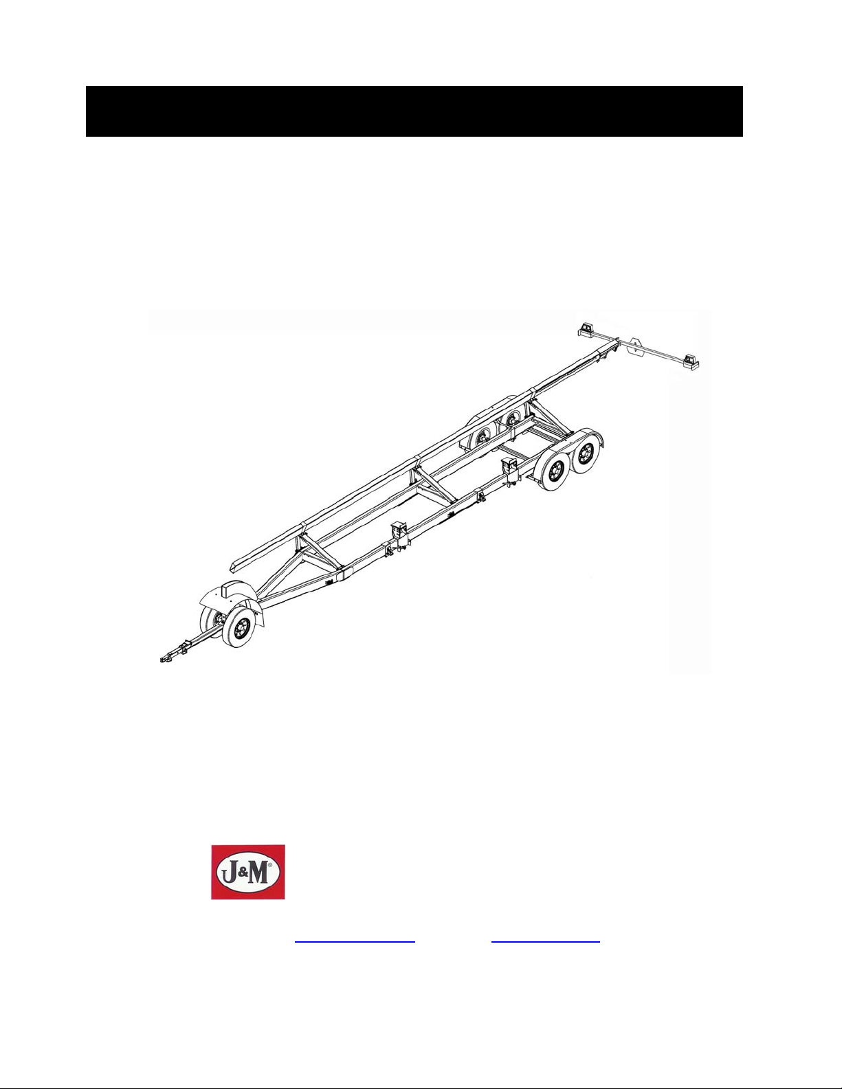
Trail-Blazer Header Transports
Commercial Grade Header Transport
Ag Version
J. & M. Manufacturing Co., Inc.
P.O. Box 547
Fort Recovery, OH 45846
Phone: (419) 375 2376 Fax: (419) 375-2708
E-mail: sales@jm-inc.com
Website: www.jm-inc.com
REV-12-15-08
Pg. 1
Page 2

TO THE DEALER:
Read manual instructions and safety rules. Make sure all items on the Dealer’s Pre-Delivery and Delivery Check
Lists in the Operator’s Manual are completed before releasing equipment to the owner.
The dealer must complete the Warranty Registration Card attached to the front inside cover of this manual and return
to J. & M. Mfg. Co., Inc. at the address indicated on the card. Warranty claims will be denied if the Warranty
Registration Card has not been completed and returned.
EXPRESS WARRANTY:
J. & M. Mfg. Co. Inc. warrants against defects in construction or materials for a period of ONE year. We reserve the
right to inspect and decide whether material or construction was faulty or whether abuse or accident voids our
guarantee.
Warranty service must be performed by a dealer or service center authorized by J. & M. Mfg. Co. Inc. to sell and/or
service the type of product involved, which will use only new or remanufactured parts or components furnished by J.
& M. Mfg. Co. Inc. Warranty service will be performed without charge to the purchaser for parts or labor based on the
Warranty Labor Times schedule. Under no circumstance will allowable labor times extend beyond the maximum
hours indicated in the Warranty Labor Times schedule for each warranty procedure. The purchaser will be
responsible, however, for any service call and/or transportation of the product to and from the dealer or service
center’s place of business, for any premium charged for overtime labor requested by the purchaser, and for any
service and/or maintenance not directly related to any defect covered under the warranty. Costs associated with
equipment rental, product down time, or product disposal are not warrantable and will not be accepted under any
circumstance.
Each warranty term begins on the date of product delivery to the purchaser. Under no circumstance will warranty be
approved unless (i) the product warranty registration card (attached to the inside of the Operator’s Manual) has been
properly completed and submitted to the equipment manufacturer. This Warranty is effective only if the warranty
registration card is returned within 30 days of purchase.
This warranty does not cover a component which fails, malfunctions or is damaged as a result of (i) improper
modification or repair, (ii) accident, abuse or improper use, (iii) improper or insufficient maintenance, or (iv) normal
wear or tear. This warranty does not cover products that are previously owned and extends solely to the original
purchaser of the product. Should the original purchaser sell or otherwise transfer this product to a third party, this
Warranty does not transfer to the third party purchaser in any way. J. & M. Mfg. Co. Inc. makes no warranty, express
or implied, with respect to tires or other parts or accessories not manufactured by J. & M. Mfg. Co. Inc. Warranties
for these items, if any, are provided separately by their respective manufacturers.
THIS WARRANTY IS EXPRESSLY IN LIEU OF ALL OTHER WARRANTIES OR CONDITIONS, EXPRESS,
IMPLIED OR STATUTORY, INCLUDING ANY IMPLIED WARRANTY OF MERCHANTABILITY OR FITNESS FOR
PARTICULAR PURPOSE.
In no event shall J. & M. Mfg. Co. Inc. be liable for special, direct, incidental or consequential damages of any kind.
The exclusive remedy under this Warranty shall be repair or replacement of the defective component at J. & M. Mfg.
Co. Inc’s. option. This is the entire agreement between J. & M. Mfg. Co. Inc. and the Owner about warranty and no J.
& M. Mfg. Co. Inc. employee or dealer is authorized to make any additional warranty on behalf of J. & M. Mfg. Co.
Inc.
The manufacturer reserves the right to make product design and material changes at any time without notice. They
shall not incur any obligation or liability to incorporate such changes and improvements in products previously sold to
any customer, nor shall they be obligated or liable for the replacement of previously sold products with products or
parts incorporating such changes.
SERVICE:
The equipment you have purchased has been carefully manufactured to provide dependable and satisfactory use.
Like all mechanical products, it will require cleaning and upkeep. Lubricate the unit as specified. Observe all safety
information in this manual and safety signs on the equipment.
For service, your authorized J. & M. dealer has trained mechanics, genuine J. & M. service parts, and the necessary
tools and equipment to handle all your needs.
Use only genuine J. & M. service parts. Substitute parts may void the warranty and may not meet standards required
for safe and satisfactory operation. Record the model number and serial number of your equipment in the spaces
provided:
Serial # ___________ Purchase Date: _______ Purchased From: ____________________________________
Please provide this information to your dealer to obtain the correct parts:
Pg. 2
Page 3
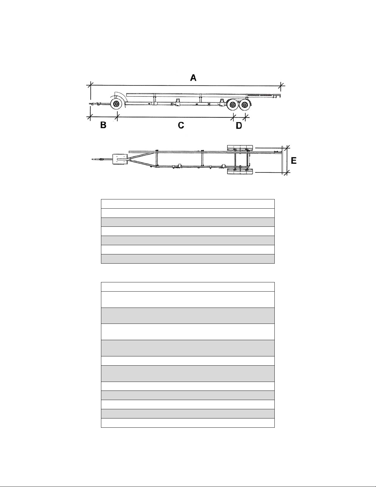
MODELS TB-3500A and TB-6000A Header Transports
Specifications
A 41’-0” 47’-0” 52’-6” 58’-6”
B 6’-0” 6’-0” 6’-0” 6’-0”
C 26’-0” 26’-0” 26’-0” 30’-0”
D 2’-10” 2’-10” 2’-10” 2’’-10”
E 6’-0” 6’-0” 6’-0” 6’-0”
DIMENSIONS (by Upper Bar Length)
32’ 38’ 42’ 48’
Capacity (Net) 8,750 lbs (TB-3500A)
Weight (approx.) 3,260 lbs (TB-3500A)
Wheels 15” x 6” (TB-3500A)
Tires 225/75R15D (TB-3500A)
Upper Bar Lengths 32’, 38’, 42’ or 48’
Adj. Header Mounts Standard
Hubs 6 bolt
Spindles Two - 2-1/4” dia. (front) and
Main Frame 4” x 8” x 3/16” steel tubing
Steel Upper Bar 4” x 8” x 3/16” steel tubing
Tie Down Straps Standard
SPECIFICATIONS
15,700 lbs (TB-6000A)
3,500 lbs (TB-6000A)
16” x 6” (TB-6000A)
235/85R16D (TB-6000A)
Four - 2-1/2” dia. (rear)
Pg. 3
Page 4
GENERAL INFORMATION
TO THE OWNER:
The purpose of this manual is to assist you in operating and maintaining your running gear in a safe
manner. Read it carefully. It furnishes information and instructions that will help you achieve years of
dependable performance and help maintain safe operating conditions. If this machine is used by an
employee or is loaned or rented, make certain that the operator(s), prior to operating:
1. Is instructed in safe and proper use.
2. Reviews and understands the manual(s) pertaining to this machine.
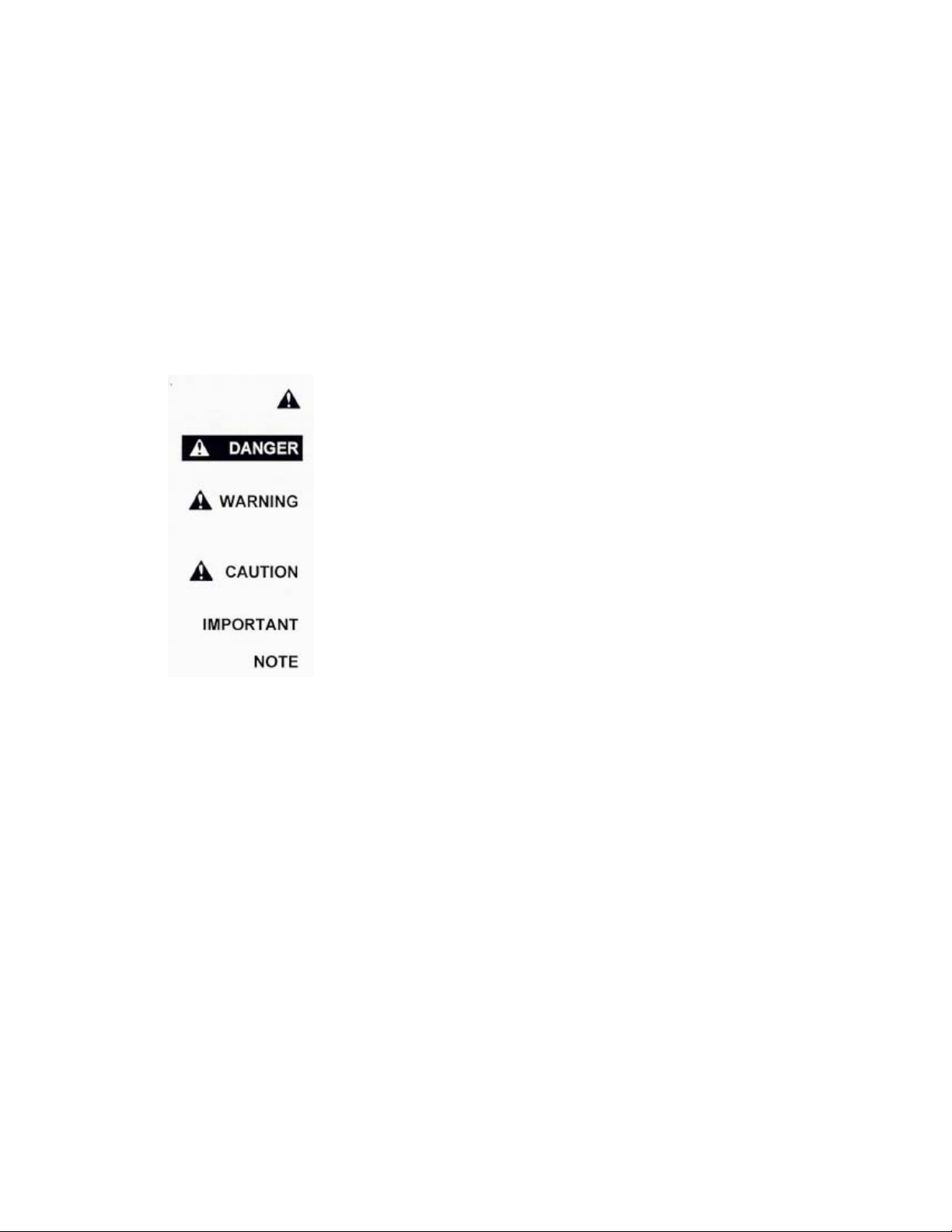
Throughout this manual, the term IMPORTANT is used to indicate that failure to observe can cause
damage to equipment. The terms CAUTION, WARNING and DANGER are used in conjunction with the
Safety-Alert Symbol, (a triangle with an exclamation mark), to indicate the degree of hazard for items of
personal safety. When you see this symbol, carefully read the message that follows and be alert to the
possibility of personal injury or death.
This Safety-Alert symbol indicates a hazard and means
ATTENTION! BECOME ALERT! YOUR SAFETY IS INVOLVED!
Indicates an imminently hazardous situation that, if not avoided, will
result in death or serious injury.
Indicates a potentially hazardous situation that, if not avoided, could
result in death or serious injury, and includes hazards that are exposed
when guards are removed.
Indicates a potentially hazardous situation that, if not avoided, may result
in minor or moderate injury.
Indicates that failure to observe can cause damage to equipment.
Indicates helpful information.
Pg. 4
Page 5
GENERAL INFORMATION (continued)
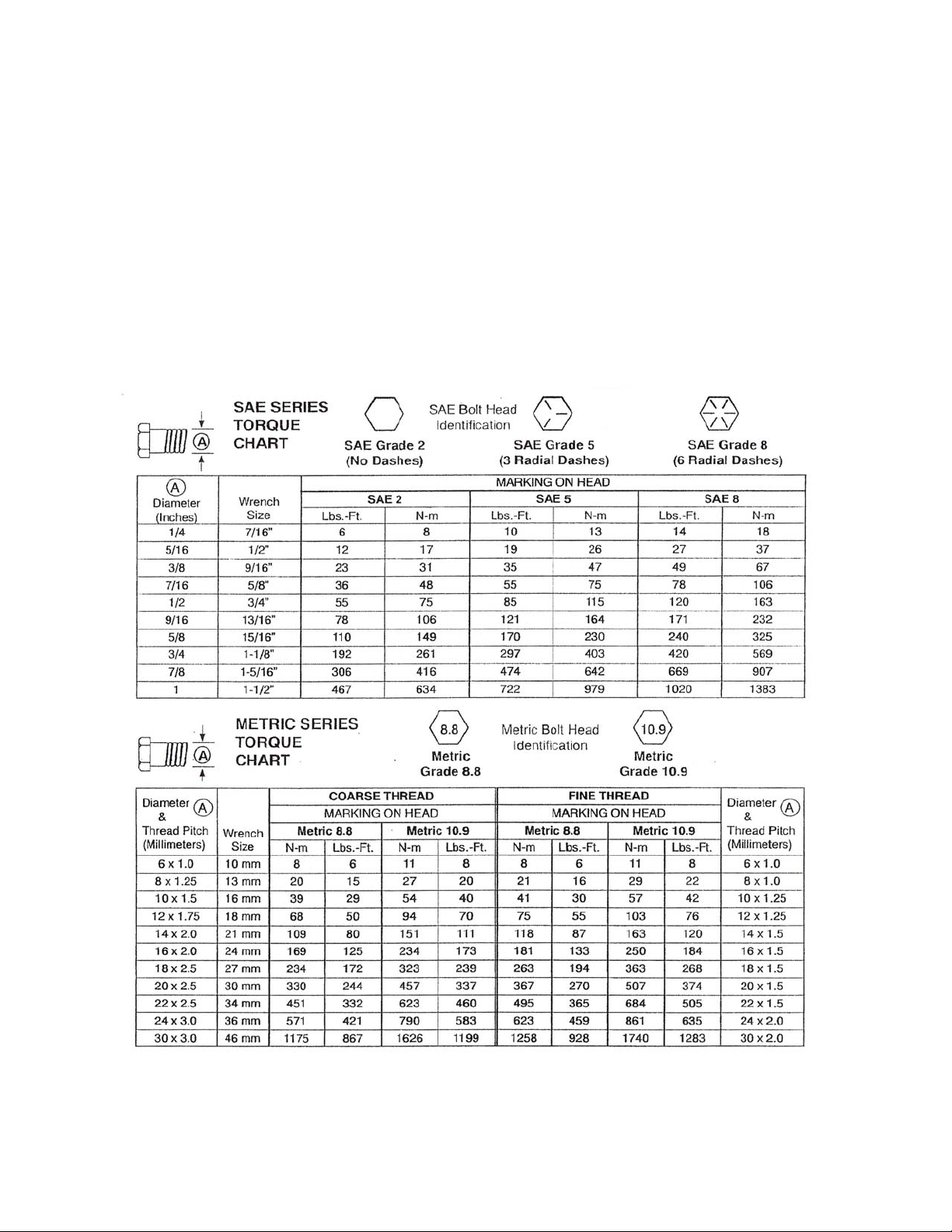
BOLT TORQUE CHART
Always tighten hardware to these values unless a different torque or tightening procedure is listed for a
specific application.
Fasteners must always be replaced with the same grade as specified in the manual parts list.
Always use the proper tool for tightening hardware. SAE for SAE hardware and Metric for metric
hardware.
Make sure fastener threads are clean and you start the thread engagement properly. All torque values
are given to specification used on hardware defined by SAE J1701 & J1701M (Jul 96).
Pg. 5
Page 6

TABLE OF CONTENTS
INTRODUCTION 2
EXPRESS WARRANTY 2
SPECIFICATIONS 3
GENERAL INFORMATION 4
BOLT TORQUE CHART 5
SAFETY RULES 7
SAFETY 7
SAFETY SIGNS 8
SET-UP INSTRUCTIONS 8-12
REPAIR PARTS LIST
Main Frame and Upper Bar 13
Front Axle Assembly 13
Tie-Down Bracket and Adjustable Header Mount 14
Adjustable Upper Bar Mount 14
Rear Axle Assembly 15-16
Rear Fender Assembly 16
Light Kit 17-18
INITIAL OPERATION / MAINTENANCE 19
SERVICE / MAINTENANCE RECORD 20
Pg. 6
Page 7

SAFETY RULES
ATTENTION! BECOME ALERT! YOUR SAFETY IS INVOLVED!
Safety is a primary concern in the design and manufacture of our products. Unfortunately, our efforts to
provide safe equipment can be erased by an operator’s single careless act. In addition, hazard control
and accident prevention are dependent upon the awareness, concern, judgment, and proper training of
personnel involved in the operation, transport, maintenance and storage of equipment.
Make certain that the operator(s), prior to operating is instructed in safe and proper use and reviews and
understands the manual(s) pertaining to this machine.
Read this manual before you operate this machine. If you do not understand any part of this manual, or
need more information, contact the manufacturer or your authorized dealer.
SAFETY
9 Understand that your safety and the safety of other persons are measured by how you service, and
operate this machine. Know the positions and functions of all controls before you try to operate them.
Make sure to check all controls in a safe area before starting your work.
9 The safety information given in this manual does not replace safety codes, federal, state or local laws.
Make certain your machine has the proper equipment as designated by local laws and regulations.
9 A frequent cause of personal injury or death is from persons falling off equipment and being run over. Do
not permit persons to ride on this machine.
9 Travel speeds should be such that complete control and machine stability is maintained at all times.
Where possible, avoid operating near ditches, embankments and holes. Reduce speed when turning,
crossing slopes and rough, slick or muddy surfaces.
9 Collision of high speed road traffic and slow moving machines can cause personal injury or death. On
roads, use flasher lights according to local laws. Keep slow-moving-vehicle emblem visible. Pull over to
let faster traffic pass.
9 Make sure that the header is fastened securely to the transport before moving.
9 Make sure that everyone is clear of equipment before applying power or moving the machine. NEVER
position yourself under or near header when mounting on header transport.
9 Never adjust, service, clean or lubricate the header transport until all power if shut off.
9 Make sure that the implement is fastened securely to the tractor by using the proper hitch pin, clip and
safety chains.
9 Before unhooking the implement from the towing unit, be sure to properly block the wheels to prevent the
implement from moving.
9 Never overload the header transport. Overloading the header transport is dangerous and can cause
extensive damage.
9 Do NOT exceed speeds in excess of 25 MPH. The header transport is designed for heavy loads at slow
speeds. Also be sure slow moving vehicle emblem is attached to rear of wagon.
9 IMPORTANT: Use caution when transporting. Be alert of the transport unit’s overall width when
approaching obstacles, such as post signs and poles, along the road. Check the transport width of the
unit to ensure clearance before entering bridges.
9 COMPLY WITH ALL SAFETY WARNINGS AND CAUTIONS IN THIS MANUAL AND IN THE COMBINE
OPERATORS MANUAL.
9 WARNING: BE SURE ALL LIGHTS ARE WORKING PROPERLY BEFORE
Pg. 7
HIGHWAY TRAVEL.
Page 8
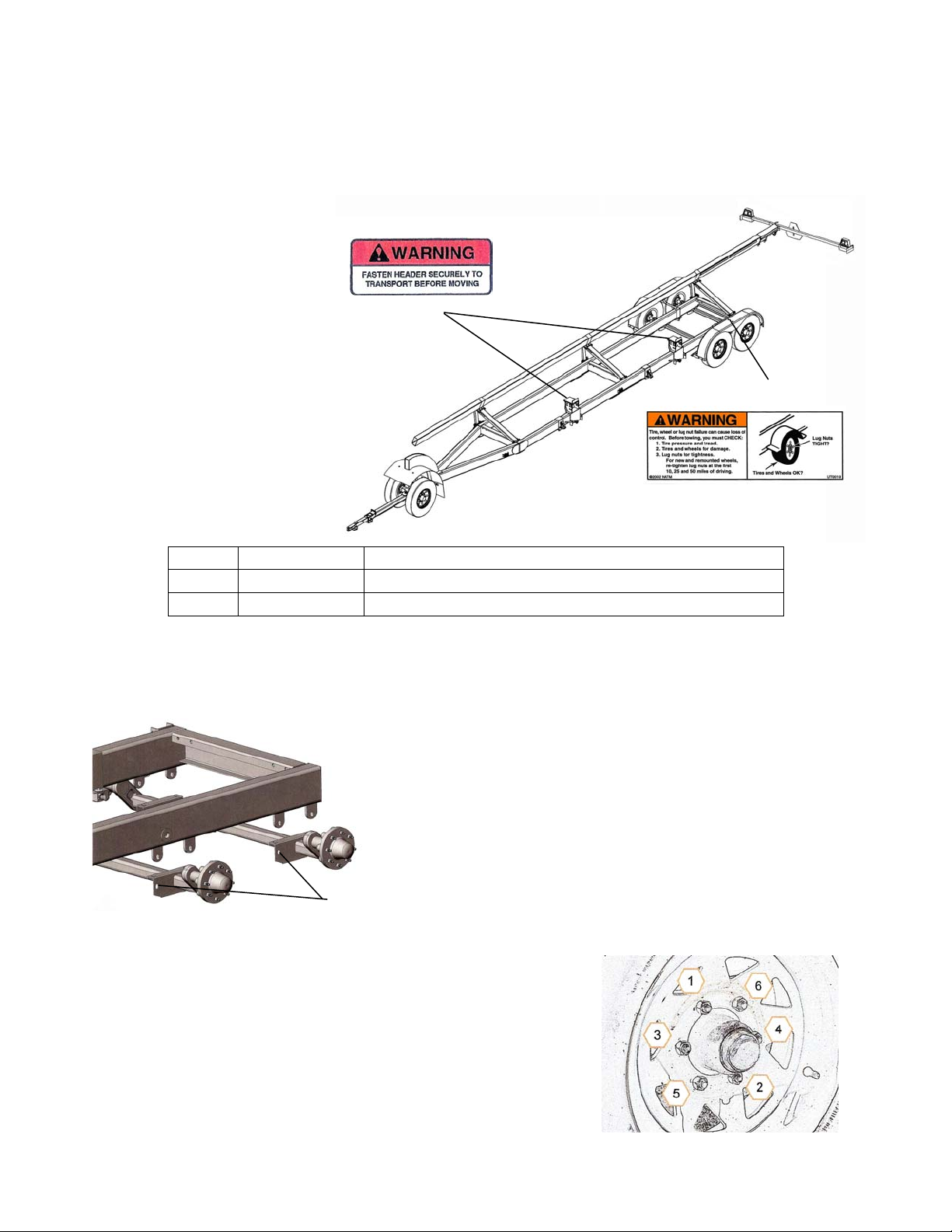
9 SAFETY SIGNS
ATTENTION: BECOME ALERT! YOUR SAFETY IS INVOLVED!
Replace Immediately If Damaged or Missing!
IMPORTANT: Install new
safety signs if the old signs
are destroyed, lost, painted
over or cannot be read.
When parts are replaced that
have safety signs, make sure
you install a new sign with
DW-108
each new part. New signs
are available from the
manufacturer or your
authorized dealer.
DECAL PARTS LIST
Item # Part # Description
1 DW-121 Warning: Tire, Wheel, Lug Nut
2 DW-108 Warning: Fasten Header Securely
SET-UP INSTRUCTIONS
IMPORTANT: Set-up work to be performed by qualified servicemen only.
1. Mounting the Rear Axles
Secure the Dura-Flex Axles to the axle mounts located on the
underside of the Header Transport Main Frame using four 5/8” x 13/4” Grade 5 bolts with eight 5/8” flat washers and four 5/8”
locknuts. NOTE: The axle should be positioned so the spindle
is located toward the rear of the axle centerline.
Align the holes on each side of the Dura-Flex Axle with the
tabs welded to the underside of the Main Frame.
2. Mounting the Tires
Secure one tire and wheel assembly to each of the rear hub
assemblies using the wheel nuts provided. Use a star pattern to
tighten the spindle nuts according to SAE standards.
DW-121
Pg. 8
Page 9

SET-UP INSTRUCTIONS (continued)
pp
Base Fender
ort Rail
Su
Fender
Support
Arm
L-Bracket
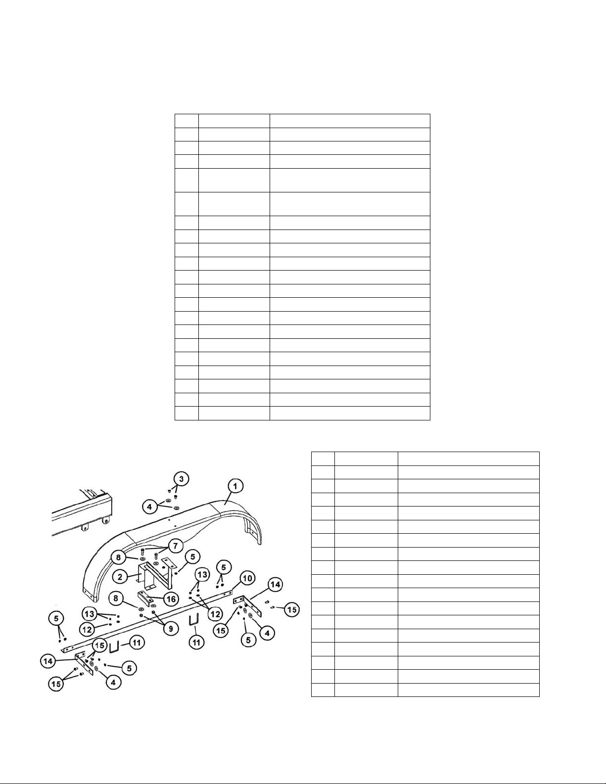
Mount one Fender L-Brackets to the front end of the fender using two 3/8” x 1” flange bolts, two 3/8”
washers and two 3/8” whiz nuts. Secure one Fender L-Bracket and Light Mounting Bracket to the rear
end of the fender using two 3/8” x 1” flange bolt, two 3/8” washers and two 3/8” whiz nuts. Secure the
other side of the L-Bracket to the Base Fender Support Rail using two 3/8” x 1” flange bolts and two 3/8”
whiz nuts. Repeat on opposite side of transport.
3. Mounting the Rear Fenders
Place one of the Base Fender Support Rail (left or right) on top
of the two rear axles between the main frame and spindle as
shown. Align the holes in the support rail with the rear axles and
loosely secure to each axle using one 3/8” x 3 1/2” x 3 1/2” UBolt, two 3/8” flat washers and two 3/8” lock nuts.
IMPORTANT: Be sure the vertical face of the support rail faces
the outside of the transport (toward the tires) and the support rail
extends farther behind the second rear axle than it does the first
rear axle. If the support rail does not project farther behind the
second rear axle, the rail is located on the wrong side of the
transport and the other rail should be used.
Repeat on opposite side of transport.
Slide the Fender Support Arm across the header transport main
frame and loosely secure to the Angle Iron Support using two
1/2” x 1 1/2” Grade 5 bolts, two 1/2” washers and two 1/2” lock
nuts. Mount the Fender to the top of the Fender Support Arm
using two 3/8” x 1” flange bolts, two 3/8” rubber/metal washers
and two 3/8” whiz nuts. Be sure the side tear drop of the fender
is located toward the outside of the transport. Slide the Fender
Support Arm along the main frame until the fender is centered
above the tires to ensure proper clearance.
Repeat on opposite side of transport.
4. Mounting the Front Axle Assembly
Mount two wheels and tires to the hubs on the Ball Hitch Tongue
and Axle Assembly. Use a star pattern to secure the wheel rim
to the hub and tighten to SAE specifications. Once both wheels
are secured to the front axle, raise the spring loaded pin on the
Header Transport Main Frame and engage the ball hitch on the
Front Axle Assembly. (Be sure the ball is greased before
attaching to the gooseneck frame.) Once the ball hitch has
engaged the locking tube, lower the spring loaded pin into the
hole located on the Front Axle Assembly to prevent the
assembly from unlatching during transport.
Pg. 9
Page 10

SET-UP INSTRUCTIONS (continued)
Upper Bar Channel Support
5. Attaching the Adjustable Brackets and Upper Bar
Slide
Bracket
Secure the Upper Bar Channel Support to the left side of the
three cross frame channels on the Main Base Frame using one
5/8” x 6” pin and hair pin. Secure the Upper Bar Support Arm to
the vertical u-brackets located on the right side of the Main Base
Frame using one 5/8” x 6” pin and hair pin. Connect the channel
Support
Arm
arm to the support arm using one 5/8” x 6” pin and hair pin. The
support arms and channel arms can be adjusted and pinned to
obtain many different heights and positions.
IMPORTANT: Make sure that all three assemblies are
positioned at the same location and height to ensure the upper
bar will fit properly.
Secure the Upper Bar Slide Bracket to each the three channel arm using two 5/8” x 6” pins and hair pins.
Be sure to position all three slide brackets at the same position on the channel arm. Position the Upper
Bar on top of the three slide brackets and secure using the Upper Bar Clamps and two 1/2” washers and
two 1/2” lock nuts. The angle of the Upper Bar can be adjusted by removing and repositioning the 5/8” x
6” Hitch Pins in the Upper Bar Adjustable Brackets.
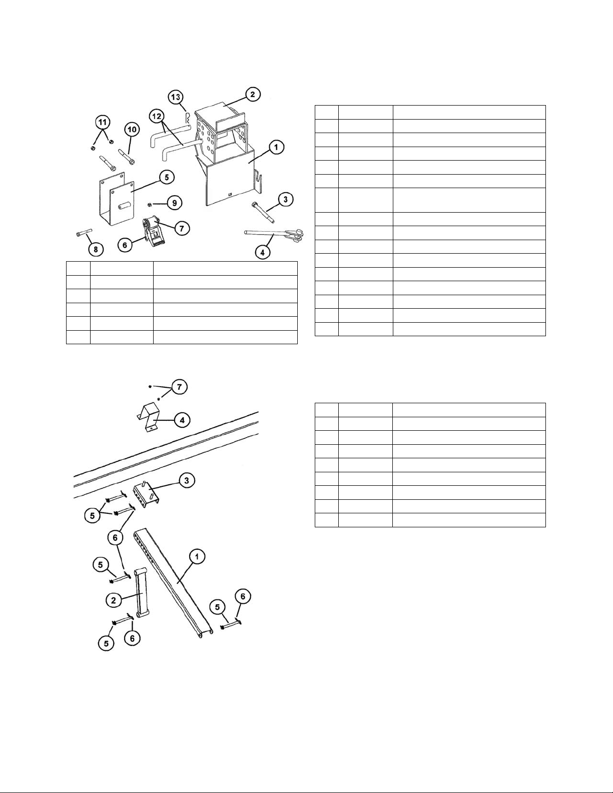
6. Attaching the Adjustable Header Mounts and Tie-Down
Brackets
Adjustable
Header
Mount
Place the Adjustable Header Mounts and Tie-Down Bracket
Assemblies on the outside left tube of the header transport main
frame as shown. Position one Adjustable Header Mount and
Tie-Down Bracket Assembly on each side of the center cross
member. Secure the Adjustable Header Mount to the outside
TieDown
Bracket
tube using one 3/4” x 6 1/2” Stove Bolt and Clamp Handle
Assembly.
Secure the Tie-Down Bracket to the outside tube using two 1/2”
x 5 1/2” Bolts and two 1/2” Lock Nuts. Do Not Tighten the 1/2” bolts on the top of the assembly, but allow
the Tie-Down Brackets to move freely along the outer tube. The Tie-Down Bracket can be secured with
the bolts either above or below the main frame tubing as long as the ratchet is positioned with the strap
directed upward.
Pg. 10
Page 11

SET-UP INSTRUCTIONS (continued)
7. Installing the Light Kit
A. Insert the Main Wiring Harness, end opposite the Flat-
Four Connector End, through the grommet located at
the front of the gooseneck of the Header Transport Main
Frame and exit the A-Frame behind the gooseneck.
B. Extend the Main Wiring Harness along the inside right
side of the Header Transport Main Frame. Reinsert the
Main Wiring Harness through the grommet located along
the front of the A-Frame and extend the harness through
the main frame tubing toward the rear of the transport.
C. Exit the Main Wiring Harness at the grommet located
behind the rear axles.
D. Secure the Light Enhancer to the inside face of the rear
Main Frame using two self-tapping screws. Connect the
end of the Main Wiring Harness to the corresponding
connector end of the Light Enhancer.
E. Place the extension bracket at the rear end of the Upper
Bar. Attach using the two angle iron supports and
secure with four 1/2” x 7” bolts, washers and nuts.
F. Place the Light Mounting Bracket at the end of the Exension Bracket Arm so the Light Mounting
Bracket is level or horizontal and extends toward the center of the header transport. Secure
using two 1/2” x 1 1/4” Grade 5 Flange Bolts and Flange Nuts.
G. Slide the extendable portion of the Telescoping Arm into the Light Mounting Bracket and tighten
the Handle Nut until the bracket is secure. Extend the arm until the light assembly is within 16” of
the outer extremity of the unit.
H. Mount one light assembly at the end of the Light Mounting Bracket (L/H light) and another
assembly at the end of the Telescoping Arm (R/H light). Secure each light assembly using four
small self-tapping screws. Each light assembly should be mounted so the single amber light is
positioned toward the outside of the header, and the amber and red lights are facing rearward.
Secure the SMV Emblem to the Light Mounting Bracket using two 1/4” x 1” Bolts and Lock Nuts.
Be sure the SMV Emblem remains visible from the rear during highway transport.
I. Place one amber reflective decal at the outward and front side of both the Telescoping Arm and
Light Mounting Bracket as shown. Place one Red and Orange Reflective Decal on the rearward
end of the Telescoping Arm and Light Mounting Bracket. The red reflective decal should be
placed directly above the orange decal.
J. The Main Wiring Harness should already be installed in the Main Frame Base Unit and connected
to the Light Enhancer attached to the rear of the Main Frame Base Unit. Connect each light to
the Light Enhancer using the Light Wiring Harness. Using the enclosed self tapping screws,
secure the Wire Cover over the Light Wire Harness along the upper bar.
Pg. 11
Page 12

SET-UP INSTRUCTIONS (continued)
8. Placing the Amber, Red and Orange Reflective Decals
Place the reflective decals as shown below.
9. Installing the Safety Chain Around the Ball Hitch Axle
Weldment
Bolt the ring end of the safety chain to the underside of the
gooseneck using one 3/4” x 5” Grade 8 Bolt and 3/4” Lock
Nut. Loop the chain around the Strap Weldment located on
the back side of the front axle.
Amber Decal
Amber Decal Amber Decal
Amber Decal
Amber Decal
Red Decal
Orange Decal
Amber Decal
Pg. 12
Page 13

Main Frame and Upper Bar
# Part # Description
1 HHMF2 Header Transport Main Frame
1 HHMF2L Transport Main Frame (for units
equipped with 48' upper bar)
Front Axle Assembly
PARTS LIST
# Part # Description
2 UB-24H 4" x 8" x 24' Upper Bar (takes two
plus splice plate to make 48' bar)
2 UB-42H 4" x 8" x 42' Upper Bar
2 UB-38H 4" x 8" x 38' Upper Bar
2 UB-32H 4” x 8” x 32’ Upper Bar
3 SP-24H Splice Plate (2 pcs)
4 12312B 1/2” x 3 1/2” Bolt
5 12-W 1/2” Regular Washer
6 12-LN 1/2” Lock Nut
# Part # Description
1 OT-HC Outer Tongue Weldment
2 IT-610NS Inner Tongue Weldment
3 TL-610NS Tongue Latch
4 78214-BS 7/8” x 2 1/4” Bolt with spacer
5 LS-610 Latch Shaft, 1” dia. x 5 3/4”
6 SB-212 Spacer Blocks
7 SS-615NS Small Spring in Latch
# Part # Description
8 124BG5 1/2” x 4” Grade 5 Bolt
9 12LN 1/2” Lock Nut
10 FS-HC1 Front Spindle
11 27001500 Grease Seal
12 25580 Large Bearing (0170012C)
13 104082 Small Bearing
14 HC-SW Spindle Washer
15 SN-HC1 Slotted Spindle Nut
16 HC-CP Cotter Pin
17 3160333 Hub, 6 Bolt w/cups & studs
18 HCWS-1 Wheel Stud
19 WN-HC1 Wheel Nut
20 502019 Dust Cap
21 WR-156-6HC Wheel Rim, 15x6, 6 hole
21 WR-166-6HC Wheel Rim, 16x6, 6 hole
22 ST225-75E 15” New Tire (TB-3500A)
22 ST235-85D 16” New Tire (TB-6000A)
23 25520 Large Race (not shown)
24 67010 Small Race (not shown)
Pg. 13
Page 14
PARTS LIST
# Part # Description
1 AB-L2 Lower Adjustable Bracket
2 AB-U2L Upper Adjustable Bracket, Left
2 AB-U2R Upper Adjustable Bracket, Right
2 AB-U2L-MD R/H Upper Adj. Bracket, MacDon
2 AB-U2R-MD L/H Upper Adj. Bracket, MacDon
Adjustable Upper Bar Mount
Tie-Down Bracket and Adjustable Header Mount
# Part # Description
3 SB34612 Stove Bolt, 3/4” x 6 1/2”
4 CHA2 Clamp Handle Assembly
5 TDMB-2 Tie Down Mounting Bracket
6 RA-1 Ratchet
7 TDS-1 Tie-Down Strap and Hook Assy
7 TDS-1L Tie-Down Strap and Hook Assy
w/D-Ring Strap (MacDon Heads)
8 12234G8B 1/2” x 2 3/4” Grade 8 Bolt
9 12NLN 1/2” Nylon Lock Nut
10 12512G5B 1/2” x 5 1/2” Grade 5 Bolt
11 12LN 1/2” Lock Nut
12 3412P 3/4” x 12” Pin
13 HC-CP Cotter Pin
14 TDB-3 Tie Down Bracket Assy Complete
15 AHM-2 Adj. Header Mount Complete
# Part # Description
1 UBCM-3 Upper Bar Channel Mount
2 UBSA-3 Upper Bar Support Arm
3 UBSM-3 Upper Bar Slide Mount
4 UBC-3 Upper Bar Clamp
5 HP-586 5/8” x 6” Pin
6 316HP 3/16” Hair Pin
7 12LN 1/2” Lock Nut
8 12-WR 1/2” Regular Washer
Pg. 14
Page 15

(For Units Equipped WITHOUT Rear Brakes)
# Part # Description
1 7350881 Dura-Flex Axle Weldment
(TB-3500A)
1 7350881H Dura-Flex Axle Weldment
(TB-6000A)
2 58134G5B 5/8” x 1 3/4” Grade 5 Bolt
3 58FW 5/8” Flat Washer
4 58LN 5/8” Lock Nut
5 27001500 Grease Seal (TB-3500A)
(For Units Equipped WITH Optional Rear Brakes)
PARTS LIST
Rear Axle Assembly
# Part # Description
5 DL600 Grease Seal (TB-6000A)
6 25580 Large Bearing
7 104082 Small Bearing (TB-3500A)
7 15123 Small Bearing (TB-6000A)
8 HC-SW Spindle Washer
9 SN-HC1 Slotted Spindle Nut
10 HC-CP Cotter Pin
11 3160333 Hub, 6 Bolt (TB-3500A)
11 H-1206-S Hub, 6 Bolt (TB-6000A)
12 HCWS-1 Wheel Stud
13 WN-HC1 Wheel Nut
14 502019 Dust Cap (TB-3500A)
14 DC-250 Dust Cap (TB-6000A)
15 WR-156-
6HC
15 WR-166-
6HC
16 ST225-75E 15” New Tire (TB-3500A)
16 ST235-85D 16” New Tire (TB-6000A)
Rear Axle Assembly
Wheel Rim, 15x6 6 hole, HC
(TB-3500A)
Wheel Rim, 16x6 6 hole, HC
(TB-6000A)
# Part # Description
1 7350881B Dura-Flex Axle Weldment
complete with brakes (TB-3500H)
1 7350881BH Dura-Flex Axle Weldment
complete with brakes (TB-6000H)
2 58134G5B 5/8” x 1 3/4” Grade 5 Bolt
3 58FW 5/8” Flat Washer
4 58LN 5/8” Lock Nut
5 27001500 Grease Seal (HHS-30B, HHS-
36B)
5 DL600 Grease Seal (HHS-41B)
6 25580 Large Bearing
7 104082 Small Bearing (TB-3500H)
7 15123 Small Bearing (TB-6000H)
Pg. 15
Page 16
PARTS LIST
Rear Axle Assembly (continued)
(For Units Equipped WITH Optional Rear Brakes)
# Part # Description
8 HC-SW Spindle Washer
9 SN-HC1 Slotted Spindle Nut
10 HC-CP Cotter Pin
11 3160121G Hub, 6 Bolt with brake drum with cups
and studs (TB-3500H)
11 HD-1206-S Hub, 6 Bolt with brake drum with cups
and studs (TB-6000H)
12 HCWS-1 Wheel Stud
13 WN-HC1 Wheel Nut
14 502019 Dust Cap (TB-3500H)
14 DC-250 Dust Cap (TB-6000H)
15 WR-156-6HC Wheel Rim, 15x6 6 hole (TB-3500H)
15 WR-166-6HC Wheel Rim, 16x6, 6 hole (TB-6000H)
16 ST225-75E 15” New Tire (TB-3500H)
16 ST235-85D 16” New Tire (TB-6000H)
17 3160629G 12” Electric Brake (L/H) (TB-3500H)
17 3160630G 12” Electric Brake (R/H) (TB-3500H)
17 7705123 12” Electric Brake (L/H) (TB-6000H)
17 7705124 12” Electric Brake (R/H) (TB-6000H)
18 25520 Large Race (not shown)
19 67010 Small Race (TB-3500H)
19 15245 Small Race (TB-6000H)
Rear Fender Assembly
# Part # Description
1 WF-1 Wheel Fender
2 FSA-2-15 Fender Support Arm (TB-3500A)
2 FSA-2-16 Fender Support Arm (TB-6000A)
3 381G5B 3/8” x 1” Grade 5 Bolt
4 38RMW 3/8” Rubber Metal Washer
5 38WN 3/8” Whiz Nut
7 12112G5B 1/2” x 1 1/2” Grade 5 Bolt
8 12-RW 1/2” Regular Washer
9 12LN 1/2” Lock Nut
10 BFSR-L Base Fender Support Rail (left)
10 BFSR-R Base Fender Support Rail (right)
11 38312312UB 3/8” x 3 1/2” x 3 1/2” U-Bolt
12 38-FW 3/8” Flat Washer
13 38LN 3/8” Lock Nut
14 FLB-1 Fender L-Bracket
15 381FB 3/8” x 1” Flange Bolt
16 AIS-2 Angle Iron Support
Pg. 16
Page 17

PARTS LIST
Light Kit Assembly
(For Transports Equipped WITHOUT Rear Brakes)
# Part # Description # Part # Description
1L RLT-L Light Assembly (L/H) 17 12114-G5-FB 1/2” x 1 1/4” Grade 5 Flange Bolt
1R RLT-R Light Assembly (R/H) 18 127-HB 1/2” x 7” Hex Bolt
2* LWH-HHC Light Wiring Harness (rear only) 19 14LN 1/4” Lock Nut
3* LE-1B Light Enhancer (speaker) 20 12-FN 1/2” Flange Nut
4* MWH-HHC Main Wiring Harness with Flat
Four Connector End
5 LMB-1 Light Mounting Bracket 23 14STS 1/4” Self Tapping Screw
6 TA-1 Telescoping Arm 24 12-WR 1/2” Regular Washer
7 HDN-12 Handle Nut 25 UBWC-2 Upper Bar Wire Cover
8 EB-1 Extension Bracket 26 WHB-1 Wire Harness Storage Bracket
9 AIS-2 Angle Iron Support 27 RCW-1 Rubber Cap for Storage Bracket
10 SMV-1 SMV Emblem 28 1434G5B 1/4” x 3/4” Grade 5 Bolt
11 GR-134 Rubber Grommet (large) 29 OMST-1 Manual Storage Container
12 WC-1 Wire Clip
13 RD-A1 Amber Reflective Decal
14 RD-R1 Red Reflective Decal
15 RD-O1 Orange Reflective Decal
16 141-CB 1/4” x 1” Bolt
21 12-N 1/2” Regular Nut
22 38STS Self Tapping Screw
* NOTE: For Models TB-3500A and TB-6000A equipped with optional rear brakes, please see the
following page for Wiring Harness changes and optional Brake-Away Kit and Switch.
Pg. 17
Page 18

PARTS LIST
Light Kit Assembly
(For Transports Equipped WITH Optional Rear Brakes)
# Part # Description
1 MWH-HS Main Wiring Harness with 7-Prong Connector End
2 MBH-2 Main Brake Harness (blue, white)
3 BHE-2 Brake Harness Extension (black, white) for Optional 4-wheel brakes
4 LHE-L Light Harness Extension, Long (brown, green, yellow, white)
5 LE-1B Light Enhancer
6 LWH-HHC Light Wiring Harness (rear only)
7 BAW-1C Optional Brake Away Kit (white, black, blue)
8 BAS-1 Optional Brake Away Switch with cable (black, blue)
Pg. 18
Page 19
INITIAL OPERATION / MAINTENANCE
BE CERTAIN THAT ALL POWER IS SHUT OFF BEFORE SERVICING THE HEADER TRANSPORT
Before the header transport is put into service:
9 Has the Slow-Moving Vehicle Emblem been properly positioned at the rear of the header
transport?
9 Have all danger, warning, caution and important signs on the equipment been read and
understood? If employees or others use or are near this equipment, make sure that they also
have read and understood all danger, warning, caution and important signs on the equipment and
have also read the operator’s manual.
9 Are all braces, bolts, nuts, lug bolts and lug nuts properly fastened?
9 Has the header transport been properly fastened to the towing unit? Use a good quality hitch pin
with clip and safety chains.
9 Are the rear amber extremity lights properly positioned? Extend lights within 16” of the left and
right extremities of the header.
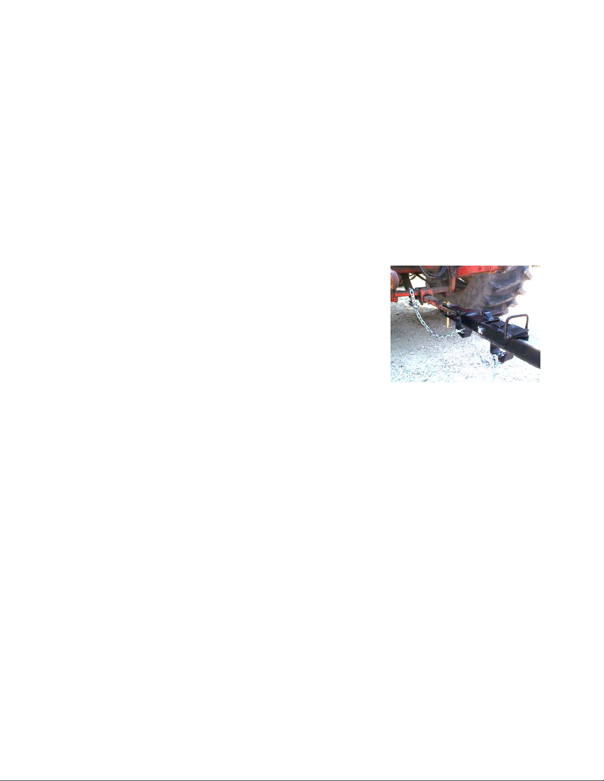
SAFETY CHAIN USER INSTRUCTIONS
a) Secure the safety chain by looping it around the tongue
support located on the underside of the Outer Tongue. Run
the chain through the intermediate support located on the
underside of the inner tongue and connect to the towing
machine’s attaching bar.
b) Do Not allow more slack than necessary for articulation.
c) Do Not use any intermediate support as the attaching point.
d) Store the safety chain by securing it around the tongue.
e) Replace the safety chain if one or more links or end fittings are
broken, stretched or otherwise damaged or deformed.
OPERATING INSTRUCTIONS/MAINTENANCE
Adjust the brackets on the header transport to best fit your make and model header. When
mounting the header, NEVER position yourself under or near the header. Securely fasten the
header to the header transport.
Do not exceed the load and size limits of the unit.
Keep the tires properly inflated. Both under inflation and over inflation can greatly reduce tire life.
Inspect bracing and welds periodically and repair immediately if needed. Failure to repair could
cause extensive damage and greatly reduce the life of the unit.
Repack the bearings in the hub assembly once a year or as needed. Use a good quality bearing
lubricant such as Bearing Gard MK1 or equivalent.
Grease the ball using the zerk on the front gooseneck assembly every 8 hours or as needed.
Be sure to check the hub nuts often and keep them properly tightened.
BRAKING SYSTEM REQUIREMENTS:
Tow Loads Safely
Stopping distance increases with speed and weight of towed loads, and on slopes. Towed loads with or
without brakes that are too heavy for the tractor or are towed too fast can cause loss of control. Consider
the total weight of the equipment and its load.
Observe these recommended maximum road speeds, or local speed limits which may be lower:
If towed equipment does not have brakes, do not travel more than 32 km/h (20 mph) and
do not tow loads more than 1.5 times the tractor weight.
If towed equipment does have brakes, do not travel more than 40 km/h (25 mph) and do
not tow loads more than 4.5 times the tractor weight.
Ensure the load does not exceed the recommended weight ratio. Use additional caution when towing
loads under adverse surface conditions, when turning, and on inclines.
Pg. 19
Page 20

SERVICE / MAINTENANCE RECORD
Date Description Notes
Pg. 20
 Loading...