

Page 1

Talc Applicator Installation Manual
For Seed Tender Models 275 & 375
J. & M. Mfg. Co., Inc.
284 Railroad Street - P.O. Box 547
Fort Recovery, OH 45846
Ph: (419) 375-2376 Fax: (419) 375-2708
www.jm-inc.com
12/19/2013
Page 2

Step 1.
Measure from the top of the shell frame and make a mark on the front right side leg at 35” for the Model 375
Seed Tender and 42” for the Model 275 Seed Tender. is mark is for the height of the Talc Holding Container.
Next using the Talc Holding Container as a guide, mark 2 holes on the side of the leg. Drill both holes with a
7/16” bit. Once the holes are drilled, fasten the Talc Holding Container with (2) 3/8”x 1” Serrated Flange Hex
Nuts and Bolts. Tighten the hardware once nished.
42” (275ST)
35” (375ST)
Step 2.
Using the Talc Control Valve Body Assembly mark (2) holes in the front le leg gusset. e bracket should be
placed at the highest point possible on the front leg gusset. Once marked, drill 2 holes with a 7/16” drill bit.
Attach the Control Valve Body Assembly with (2) 3/8” x 1” Serrated Flange Hex Head Nuts and Bolts. Tighten
hardware once nished.
Page 3
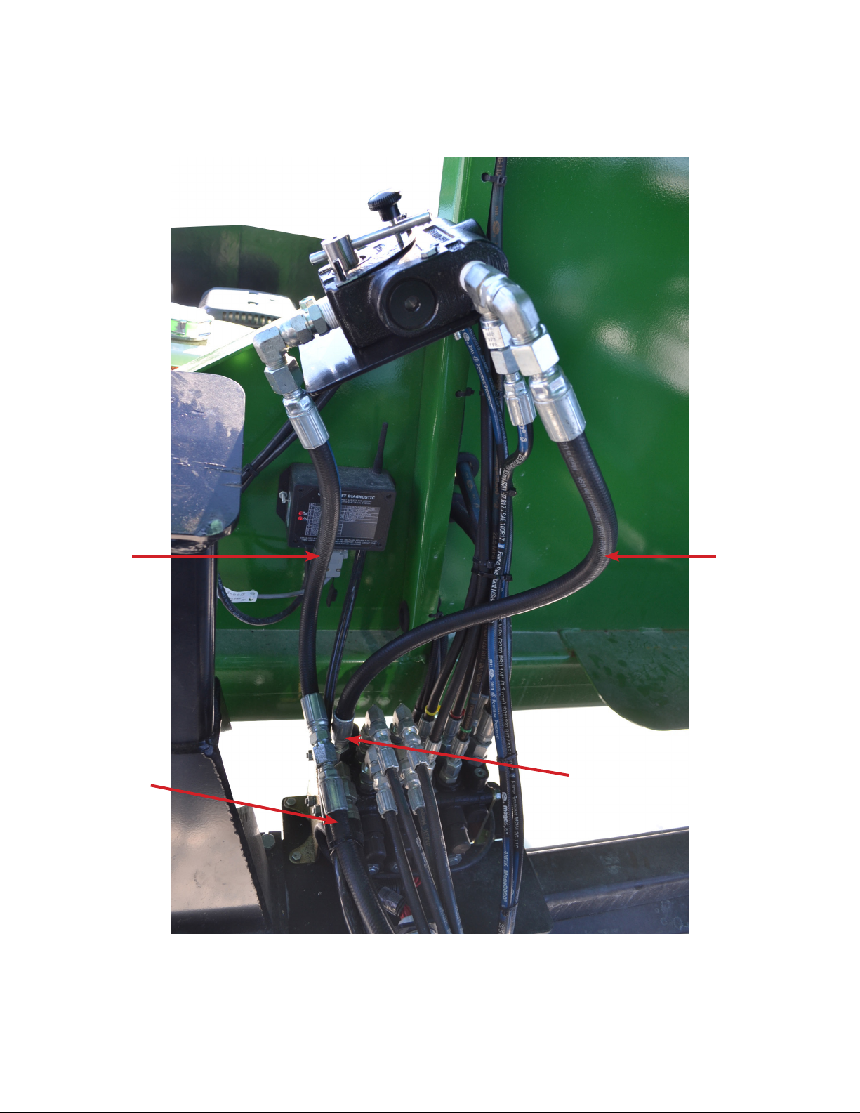
Step 3.
On the Hydraulic Spool Valve remove the “Return” hose on the valve body for the conveyor. Install the 1/2” by
17” hydraulic hose from the valve body to the Talc Applicator Control Valve. Connect hose to #3 on the talc
applicator valve body. Tighten all ttings once installed.
#3
17” Hydraulic
Hose
Conveyor
Return Hose
#4
17” Hydraulic
Hose
Remove Conveyor Return
Hose and 90 Deg. Fitting.
Step 4.
Install the last 1/2” x 17” hose. is hose connects to # 4 on the Talc Applicator Valve Body and to the Conveyor
Return Hose, which was removed from the Hydraulic Valve Body in step 3. Tighten all ttings once installed.
Note: 1/4” Hoses will be installed in step 8.
Page 4
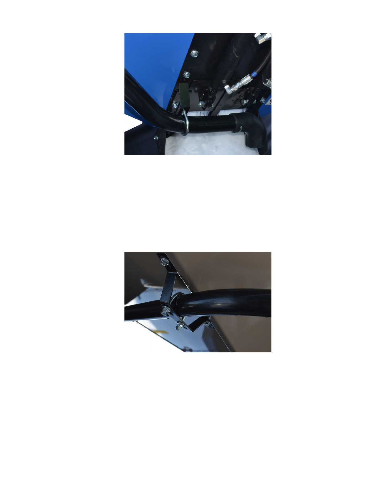
Step 5.
For 375 ST Model
Fasten the Transfer Tube to the Talc Holding Container using
the supplied bracket. Start installing the bracket by removing
the two bolts shown in the image above. Now fasten the bracket
to the door with the two nuts that were just removed. Install
the 3/8” x 3” U-bolt. Use (2) 3/8” serrated ange hex nuts and
(2) 3/8” lock nuts to fasten the U-bolt to the bracket. Tighten
hardware once installed.
Step 5.
For 275 ST Model
Fasten the Transfer Tube to the Talc Holding Container using the supplied bracket. Two 3/8” clearance holes will need
to be drilled into the shell assembly to install the bracket.
Use (2) 3/8” x 1” hex bolts and nut to fasten the bracket to
the shell assembly. Install the 3/8” x 3” U-bolt. Use (2) 3/8”
serrated ange hex nuts and (2) 3/8” lock nuts to fasten the
U-bolt to the bracket. Tighten hardware once installed.
Page 5
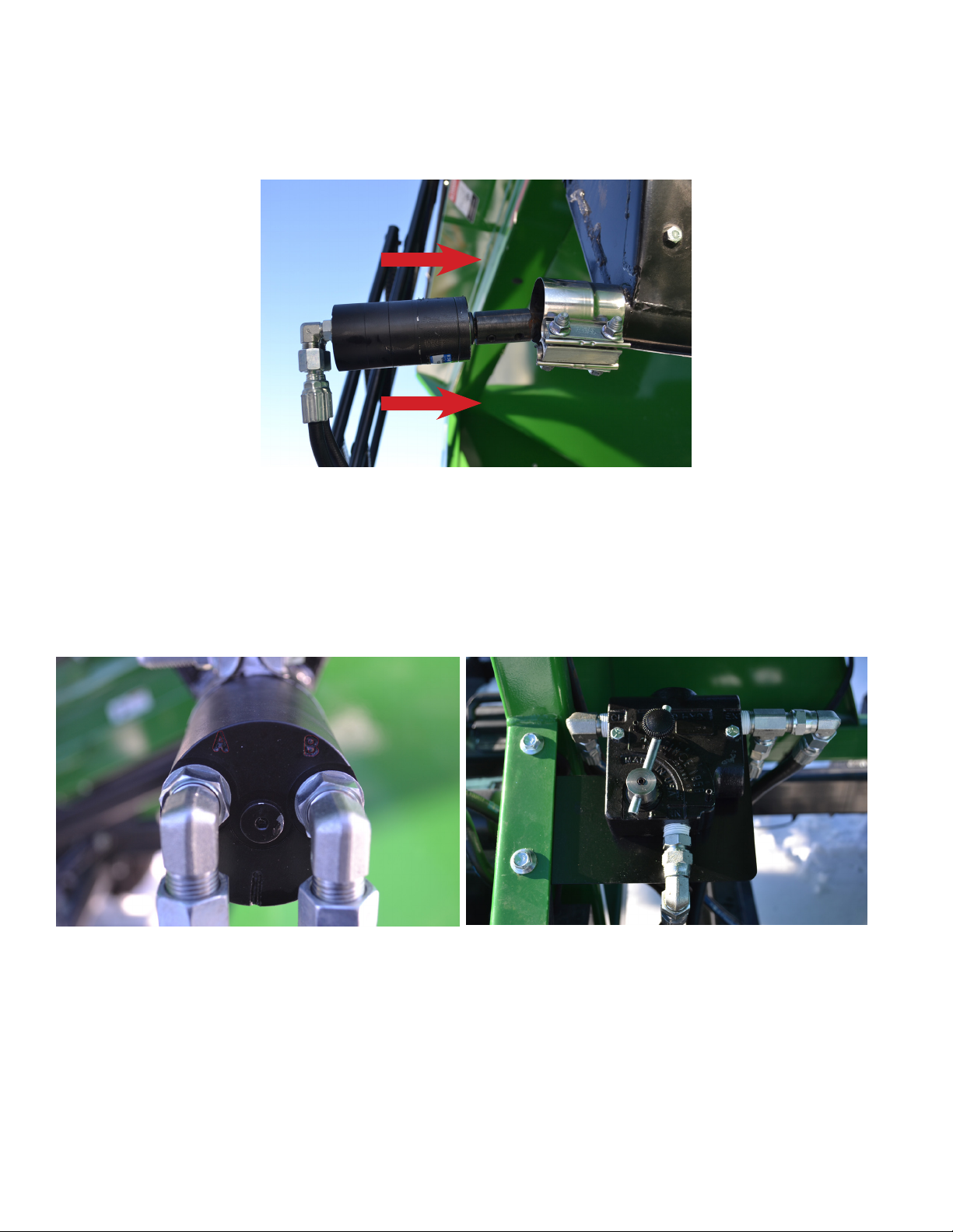
Step 6.
Install the auger through the Talc Holding Container into the Talc Transfer Tube. Attach the motor to the auger
with the supplied set screw.
Attach the Motor to the Talc Holding Container using the supplied Exhaust Clamp. Tighten hardware once nished.
Note: When installing motor make sure the key-way is installed correctly.
Step 7.
Install both 1/4” x 107” Hydraulic Hoses from the Talc Motor to the Talc Control Valve Body. Hose coming
from Port A runs to Port 1 and Port B runs to Port 2. Route the hose through the conduit on the frame. Tighten
ttings once installed.
#1
#2
Step 8.
Use zip ties to fasten hydraulic hoses where necessary. Hose’s should be fastened where they will not rub any
moving components or catch any debris during transit.
 Loading...