

Page 1

Manual
Sp e e d Te n d e r
OPERATOR’S MANUAL
MODEL
284 Railroad Street - P.O. Box 547 | Fort Recovery, OH 45846 | Ph: (419) 375-2376 | Fax: (419) 375-2708
Rev. 9.17.2019
J&M Manufacturing Co, Inc
www.jm-inc.com
Page 2

Page 3

Table Of Contents
4 ....................................................................................To the Dealer
5 .............................................................................General Information
6 .....................................................................................Safety Rules
7 ...................................................................................Specications
8 ..........................................................................................Decals
10 ......................................................................Bolt Torque Specications
11 .....................................................................................Operations
17 ................................................................................General Service
18 ........................................................................Hydraulic Power Service
19 .................................................................................... Tire Service
20 ..........................................................................Wheel Bearing Service
21 ...............................................................................Conveyor Service
24 ..................................................................................Brakes Service
27 ...............................................................................Troubleshooting
29 ....................................................................................... Controls
30 ................................................................................Throttle Control
31 ................................................................................... Valve Wiring
32 .............................................................................. Lights and Wiring
36 .............................................................................. Intercomp Wiring
37 ...............................................................................Scale Display Box
37 ................................................................................Scale Bar Mount
37 ...........................................................................Non-Scale Bar Mount
38 .............................................................................A-Frame and Hitch
39 .....................................................................................Gooseneck
40 ..................................................................................Hydraulic Jack
41 ......................................................................Brakes and Hub Assembly
42 ........................................................................................ Chassis
44 .....................................................................................Swing Arm
46 ......................................................................................Conveyor
47 ....................................................................... Conveyor Discharge End
48 .............................................................................Conveyor Idler End
50 ...........................................................................................Shell
51 ...............................................................................Spare Tire Mount
52 .........................................................................................Ladder
53 .................................................................................Hydraulic Door
54 ...................................................... Hydraulics Schematic for Aluminum Valve
56 .................................................Hydraulics Schematic for Black Intercomp Valve
58 .................................................................................Talc Applicator
59 ..................................................Talc Hydraulics Schematic for Aluminum Valve
60 .............................................Talc Hydraulics Schematic for Black Intercomp Valve
61 ..................................................................................Spring Return
62 .......................................................................................Roll Tarp
3
Page 4

To the Dealer
TO THE DEALER
Read manual instructions and safety rules. Make sure all items on the Dealer’s Pre-Delivery and Delivery Check Lists are completed before
releasing equipment to the owner.
The dealer must complete the Warranty Registration found on the Dealer Portal website located at dealer.jm-inc.com and return it to J&M
Mfg. Co., Inc. at the address indicated on the form. Warranty claims will be denied if the Warranty Registration has not been submitted.
EXPRESS WARRANTY:
J&M Mfg. Co. Inc. warrants against defects in construction or materials for a period of ONE year. We reserve the right to inspect and decide
whether material or construction was faulty or whether abuse or accident voids our guarantee.
Warranty service must be performed by a dealer or service center authorized by J&M Mfg. Co., Inc. to sell and/or service the type of
product involved, which will use only new or remanufactured parts or components furnished by J&M Mfg. Co., Inc. Warranty service will
be performed without charge to the purchaser for parts or labor based on the Warranty Labor Times schedule. Under no circumstance will
allowable labor times extend beyond the maximum hours indicated in the Warranty Labor Times schedule for each warranty procedure.
The purchaser will be responsible, however, for any service call and/or transportation of the product to and from the dealer or service
center’s place of business, for any premium charged for overtime labor requested by the purchaser, and for any service and/or maintenance
not directly related to any defect covered under the warranty. Costs associated with equipment rental, product down time, or product
disposal are not warrantable and will not be accepted under any circumstance.
Each warranty term begins on the date of product delivery to the purchaser. Under no circumstance will warranty be approved unless (i)
the product warranty registration card has been properly completed and submitted to the equipment manufacturer, and (ii) a warranty
authorization number has been issued by the equipment manufacturer. This Warranty is eective only if the warranty registration card is
returned within 30 days of purchase.
This warranty does not cover a component which fails, malfunctions or is damaged as a result of (i) improper modication or repair, (ii)
accident, abuse or improper use, (iii) improper or insucient maintenance, or (iv) normal wear or tear. This warranty does not cover
products that are previously owned and extends solely to the original purchaser of the product. Should the original purchaser sell or
otherwise transfer this product to a third party, this warranty does not transfer to the third party purchaser in any way. J&M Mfg. Co.,
Inc. makes no Warranty, express or implied, with respect to tires or other parts or accessories not manufactured by J&M Mfg. Co., Inc.
Warranties for these items, if any, are provided separately by their respective manufacturers.
THIS WARRANTY IS EXPRESSLY IN LIEU OF ALL OTHER WARRANTIES OR CONDITIONS, EXPRESS, IMPLIED OR STATUTORY, INCLUDING ANY
IMPLIED WARRANTY OF MERCHANTABILITY OR FITNESS FOR PARTICULAR PURPOSE.
In no event shall J&M Mfg. Co., Inc. be liable for special, direct, incidental or consequential damages of any kind. The exclusive remedy
under this Warranty shall be repair or replacement of the defective component at J&M Mfg. Co., Inc’s. option. This is the entire agreement
between J&M Mfg. Co., Inc. and the Owner about warranty and no J&M Mfg. Co., Inc. employee or dealer is authorized to make any
additional warranty on behalf of J&M Mfg. Co., Inc.
The manufacturer reserves the right to make product design and material changes at any time without notice. They shall not incur any
obligation or liability to incorporate such changes and improvements in products previously sold to any customer, nor shall they be
obligated or liable for the replacement of previously sold products with products or parts incorporating such changes.
SERVICE:
The equipment you have purchased has been carefully manufactured to provide dependable and satisfactory use. Like all mechanical
products, it will require cleaning and maintenance. Lubricate the unit as specied. Observe all safety information in this manual and safety
signs on the equipment.
For service, your authorized J&M dealer has trained mechanics, genuine J&M service parts, and the necessary tools and equipment to
handle all your needs.
Use only genuine J&M service parts. Substitute parts may void warranty and may not meet standards required for safety and satisfactory
operation. Record the model number and serial number of your equipment in the spaces provided:
Model No: LC290 SpeedTender Serial No: ________________________ Date of Purchase: ______________________
Purchased From: ________________________________________________________________________________
Provide this information to your dealer to obtain correct repair parts.
4
Page 5

General Information
TO THE OWNER:
The purpose of this manual is to assist you in operating and maintaining your seed tender in a safe manner. Read it carefully. It furnishes
information and instructions that will help you achieve years of dependable performance and help maintain safe operating conditions. If
this machine is used by an employee or is loaned or rented, make certain that the operator(s), prior to operating:
1. Is instructed in safe and proper use.
2. Reviews and understands the manual(s) pertaining to this machine.
Throughout this manual, the term IMPORTANT is used to indicate that failure to observe can cause damage to equipment. The terms
CAUTION, WARNING and DANGER are used in conjunction with the Safety-Alert Symbol, (a triangle with an exclamation mark), to indicate
the degree of hazard for items of personal safety. When you see this symbol, carefully read the message that follows and be alert to the
possibility of personal injury or death.
This Safety-Alert symbol indicates a hazard and means
ATTENTION! BECOME ALERT! YOUR SAFETY IS INVOLVED!
DANGER
WARNING
CAUTION
IMPORTANT
NOTE
Indicates an imminently hazardous situation that, if not avoided, will result in death or serious injury.
Indicates a potentially hazardous situation that, if not avoided, could result in death or serious injury,
and includes hazards that are exposed when guards are removed.
Indicates a potentially hazardous situation that, if not avoided, may result in minor or moderate injury.
Indicates that failure to observe can cause damage to equipment.
Indicates helpful information
.
SAFETY RULES:
ATTENTION! BECOME ALERT! YOUR SAFETY IS INVOLVED!
Safety is a primary concern in the design and manufacture of our products. Unfortunately, our eorts to provide safe equipment can
be erased by an operator’s single careless act. In addition, hazard control and accident prevention are dependent upon the awareness,
concern, judgment, and proper training of personnel involved in the operation, transport, maintenance and storage of equipment.
Make certain that the operator(s), prior to operating is instructed in safe and proper use and reviews and understands the manual(s)
pertaining to this machine. Also make certain that the operator(s) reviews and understands the operator’s manual of the tow vehicle
prior to hooking up or operating the SpeedTender.
Read this manual before you operate this machine. If you do not understand any part of this manual, or need more information,
contact the manufacturer or your authorized dealer.
Safety Rules Continued on Next Page
5
Page 6

Safety Rules
1. Understand that your safety and the safety of other persons are measured by how you service and operate this machine. Know the
positions and functions of all controls before you try to operate them. Make sure to check all controls in a safe area before starting
your work.
2. The safety information given in this manual does not replace safety codes, federal, state, or local laws. Make certain your machine has
the proper equipment as designated by local laws and regulations.
3. A frequent cause of personal injury or death is from persons falling o equipment and being run over. Do not permit persons to ride
on this machine.
4. Secure SpeedTender safety chain to towing vehicle before transporting. Do not transport without safety chains being attached to
tow vehicle.
5. Make sure that the conveyor is resting on the conveyor support with spring latch in place before transport.
6. Use good judgment when transporting SpeedTender on a highway. Always maintain complete control. Regulate speed to road
conditions. Do not transport unit with rear compartment full and front compartment empty. The unit may not be properly balanced,
osetting the tongue weight of the SpeedTender.
7. When transporting on public roads, the conveyor must be in the forward position to meet with lighting and visibility marking requirements.
8. Do not travel faster than 10 mph. during o highway travel. Drive slowly over rough ground, hill sides, and around curves to avoid
tipping. Use extreme care when operating close to ditches, fences, or on hillsides.
9. Use care when moving or operating SpeedTender near electric lines as serious injury or death can result from contact.
10. Never adjust, service, clean, or lubricate SpeedTender until all power is shut o and the battery is disconnected. Keep all safety
shields in place.
11. Carbon monoxide can cause severe nausea, fainting, or death. Do not operate engine in closed or conned work area.
12. Explosive fuel can cause res and severe burns. Stop engine before lling fuel tank.
13. Hot parts can cause severe burns. Do not touch engine while operating or just after stopping.
14. Hydraulic oil leaking under pressure can penetrate skin and cause infection or other injury.
15. To prevent personal injury when working with hydraulic power unit:
a. Relieve all pressure before disconnecting uid lines.
b. Before applying pressure, make sure all connections are tight and components are in good condition.
c. Never use your hand to check for suspected leaks under pressure. Use a piece of cardboard or wood for this purpose.
16. Make sure that everyone is clear of equipment before applying power or moving the SpeedTender.
17. Before lling the SpeedTender, make certain that no one is inside the grain tanks. Never allow children, or anyone, in, near, or on the
SpeedTender during transport or during loading and unloading of grain. Be aware that moving grain is dangerous and can cause
entrapment, resulting in severe injury or death by suocation.
18. Before unhooking the SpeedTender from the transport vehicle, be sure to properly block the wheels to prevent the SpeedTender
from moving.
19. When using the conveyor swing option be sure to stand clear of the swinging conveyor at all times.
6
Page 7

Specications
Capacity
(Total)
290 Seed
Units
Weight
(Empty)
6,100 lbs. 1,650 lbs. 22’ Long, 8”
Tongue Weight
(Loaded) Conveyor
Tube Conveyor
A
B
C
A
B
C
Unloading
Rate Conveyor Axles Engine
30 Bushels/
Minute
D JK
D JK
49’ (Front to
Rear Swing)
Two (2), 7,000 lb. Torsion-Flex
Axles with Electric Brakes
A-Frame Option Gooseneck Option
A 5’-1” 2’-10”
B 1’-10” (Max.) 3’-3” (Max.)
B 1’-6” (Min.) 2’-7” (Min.)
C 21’-3” 23’-5”
D 9’-3” 9’-3”
E 3’-10” 3’-10”
F 17’-11” 17’-11”
G 8’-6” 8’-6”
H 16’-4” (Max.) 16’-4” (Max.)
H 8’-7” (Min.) 8’-7” (Min.)
I 17’-4” (Max.) 17’-4” (Max.)
I 12’-10” (Min.) 12’-10” (Min.)
J 9’-9” 9’-9”
K 11’-0” 11’-0”
13 HP Honda Motor
with Electric Start
H
Max.
E
H
Min.
I
Max.
I
Min.
GF
7
Page 8
4
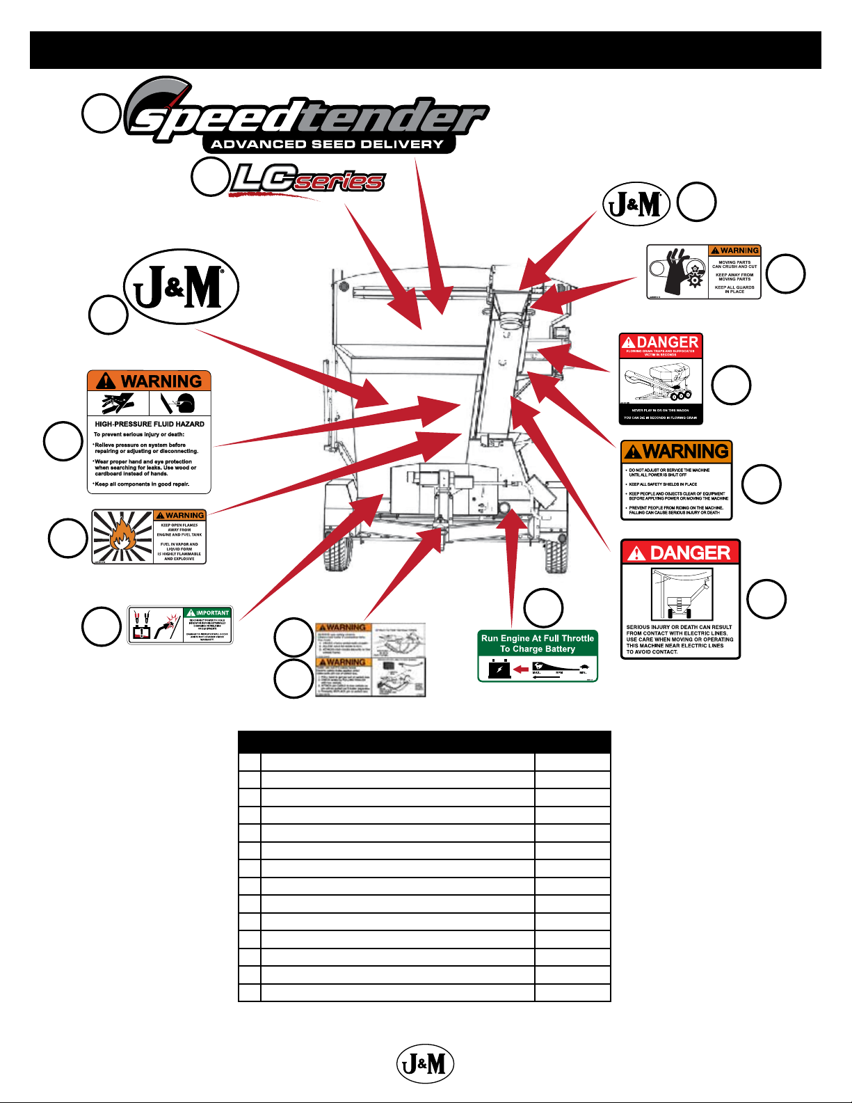
Decals
1
2
14
13
3
12
5
6
9
7
8
Description Part No.
1 SpeedTender Advanced Seed Delivery JM0040057
2 LC Series Decal JM0049466
3 J&M Oval Decal (Large) 9-1/2” x 15” JM0015151
4 Warning, High Pressure Fluid Hazard Decal 4” x 4” JM0010163
5 Warning, Keep Open Flames Away Decal JM0014983
6 Important, Disconnect Power To Scale Decal JM0040056
7 Warning, Always Use Safety Chains Decal JM0014995
8 Warning, Trailer Can Roll Decal JM0014997
9 Run Engine At Full Throttle To Charge Battery Decal JM0032425
10 Danger, Electric Lines Decal JM0015099
11 Warning, Do Not Adjust (4 Bullets) Decal JM0018040
12 Danger, Flowing Grain Traps ST Decal JM0014969
13 Warning, Moving Parts Can Crush and Cut Decal JM0014993
14 J&M Oval Decal (Medium) 5-1/2” x 8-1/2” JM0010179
11
10
8
Page 9
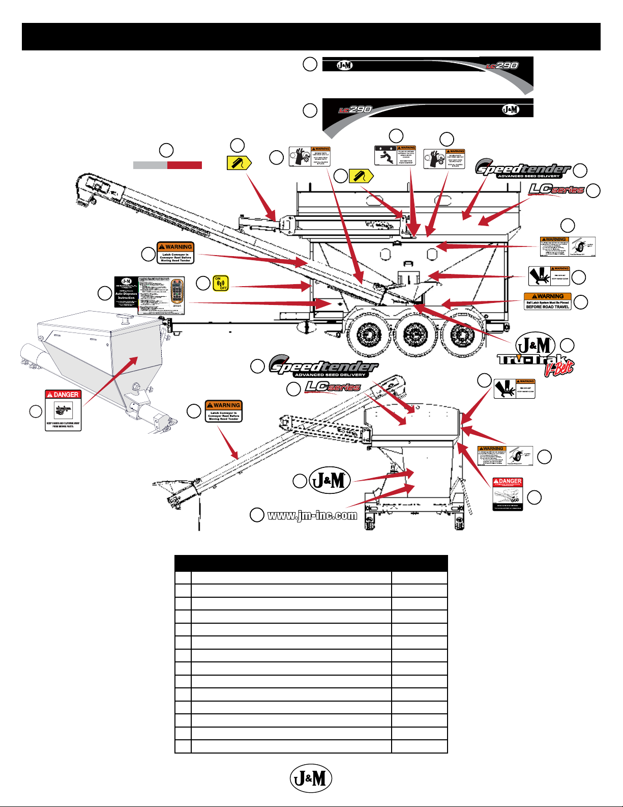
Decals
15
16
28
26
25
17
25
27
18
19
13
13
18
1
2
20
21
22
23
1
21
2
3
23
24
Description Part No.
15 LC290 Conveyor Side Stripe JM0050432
16 LC290 Opposite Conveyor Side Stripe JM0050433
17 2” x 18” Red and White Reective Strip JM0015079
18 Grease Point Decal JM0040055
19 Warning, Falling Or Lowering Decal JM0014992
20 Warning, Tire Wheel or Lug Nut Failure Decal JM0014996
21 Warning, Pinch Point Decal JM0014994
22 Warning, Ball Latch System Decal JM0040058
23 J&M Oval, Tru-Trak V-Belt Combo Decal JM0037730
24 www.jm-inc.com Decal JM0019239
25 Warning, Latch Conveyor Decal JM0040054
26 Auto Dispense Instructions Decal JM0037816
27 On/O Decal (ST) JM0014974
28 Danger, Keep Hands and Clothing Away Decal JM0018035
20
12
9
Page 10

Bolt Torque Specications
Always tighten hardware to these values unless a dierent torque or tightening procedure is listed for specic application. Fasteners must
always be replaced with the same grade as specied in the manual parts list. Always use the proper tool for tightening hardware. Make
sure fastener threads are clean and you start thread engagement properly. Use these values when tightening all bolts and nuts with
the exception of wheel nuts.
SAE Fasteners
Coarse Thread Series
Grade 5 Grade 8
Diameter and Pitch (Inches) Dry Oiled Dry Oiled
1/4”-20 8 ft-lbs 6 ft-lbs 12 ft-lbs 9 ft-lbs
5/16”-18 17 13 25 18
3/8”-16 30 23 45 35
7/16”-14 50 35 70 55
1/2”-13 75 55 110 80
9/16”-12 110 80 150 110
5/8”-11 150 110 220 170
3/4”-10 260 200 380 280
7/8”-9 430 320 600 460
1”-8 640 480 900 680
Fine Thread Series
Diameter and Pitch (Inches) Clamp Load (Lbs.) Tightening Torque Clamp Load (Lbs.) Tightening Torque
1/4”-28 10 ft-lbs 7 ft-lbs 14 ft-lbs 10 ft-lbs
5/16”-24 19 14 29 20
3/8”-24 35 25 50 40
7/16”-20 55 40 80 60
1/2”-20 90 65 120 90
9/16”-18 120 90 170 130
5/8”-18 180 130 240 180
3/4”-16 300 220 420 320
7/8”-14 470 360 660 500
Stud and Wheel Nut Torque Specications
Always tighten hardware to these values unless a dierent torque or tightening procedure is listed for specic application. Fasteners must
always be replaced with the same grade as specied in the manual parts list. Always use the proper tool for tightening hardware. Make
sure fastener threads are clean and you start thread engagement properly. Use these values when tightening all studs and wheel
nuts.
Stud Tightening Torque
1/2”-20 80 ft-lbs
9/16”-18 170 ft-lbs
5/8”-18 350 ft-lbs
3/4”-16 400 ft-lbs
20mm 475 ft-lbs
22mm 640 ft-lbs
TIGHTENING WHEEL NUTS: Torque 9/16”-18 lug nuts on wheels to 170 ft-lbs after the rst 10, 25, and 50 miles of driving, then recheck
torque every 50 hours or every year, whichever comes rst. Failure to do so may damage wheel nut seats. Once seats are damaged it
will become impossible to keep nuts tight.
10
Page 11

Operations
Preparing the Towing Vehicle
1. Before towing the SpeedTender, refer to towing vehicle’s operator’s manual for information concerning hitch capacities, hitch
adjustments, and tire ination.
2. Towing vehicle must be equipped with proper electric braking components.
NOTE: The SpeedTender is equipped with LED lights. The towing vehicle may require a asher upgrade for lights to operate
properly.
3. Do not exceed towing vehicle’s GVWR (Gross Vehicle Weight Rating) or GCWR (Gross Combination Weight Rating), or the maximum
hitch load.
Preparing SpeedTender
1. Hydraulics: Check routing of all hydraulic hoses. Hoses should not be kinked, twisted or rubbing against sharp edges. Check all
hoses and ttings for hydraulic leaks. Tighten, repair, or replace as required.
2. Lubrication: Lubricate SpeedTender as outlined in “General Service” on page 17. Refer to engine operator’s manual for proper
uid levels in engine.
3. Tires/Wheels: Check tire pressures and maintain at recommended operating pressure. It is important to check wheel nut/bolts for
proper torque as recommended. Refer to “Tire Service” on page 19 for proper tire pressure and wheel torque specications.
Connecting SpeedTender to the Towing Vehicle
WARNING: Do not stand between the SpeedTender and tow vehicle when hooking up.
NOTE: The SpeedTender comes standard with a 2-5/16” ball coupler and has an optional 3” lunette eye. Also, the SpeedTender
oers an optional gooseneck frame in place of the A-Frame. The gooseneck frame can feature either a 2-5/16” ball coupler or a
5th wheel hook up.
1. Back tow vehicle up to SpeedTender.
2. Align the vehicle’s ball or lunette eye with the coupler or ring on the SpeedTender.
3. Lift tongue latch lever.
4. Lower jack to set SpeedTender coupler down on ball or lunette eye hook.
5. Latch coupler and insert pin. Check to make sure that coupler is securely latched.
6. A-Frame - Pivot jack to transport position and pin in place.
Gooseneck - Raise the “drop leg” of the jack.
7. Attach 7-way plug to tow vehicle. Check the length of the SpeedTender 7-way plug to make sure it is long enough to turn, but not
too long to touch the ground.
NOTE: Check to make sure that lights are in proper operating condition and repair or replace if necessary.
8. Connect the brake breakaway cable to towing vehicle.
9. Attach safety chains to tow vehicle by crossing chains. Allow enough slack in chains to allow for turning.
10. Test the brakes and all the lights on the SpeedTender.
WARNING: Check safety chains for broken, stretched or damaged link or end ttings. Replace chains if found to be
damaged. Do not weld safety chains.
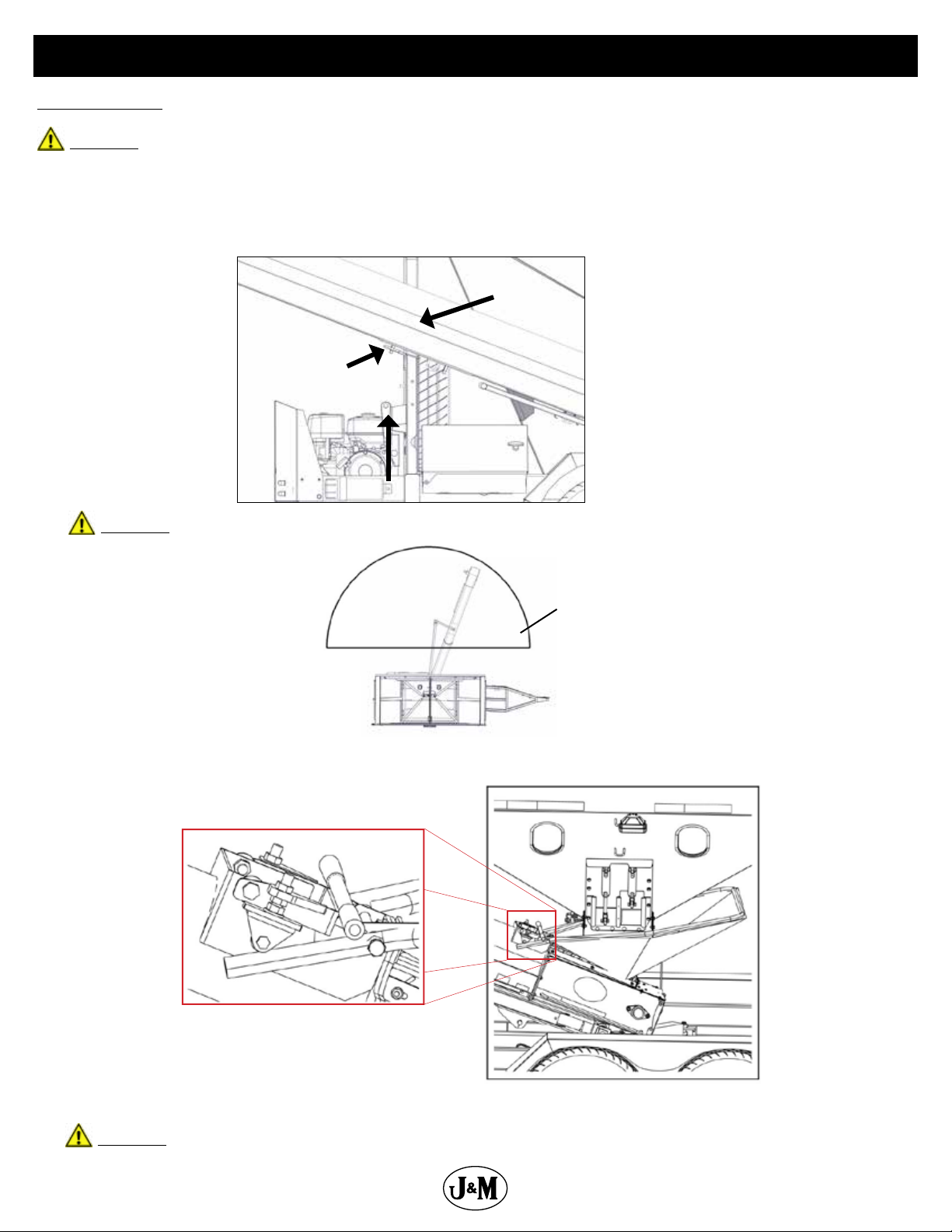
Transporting
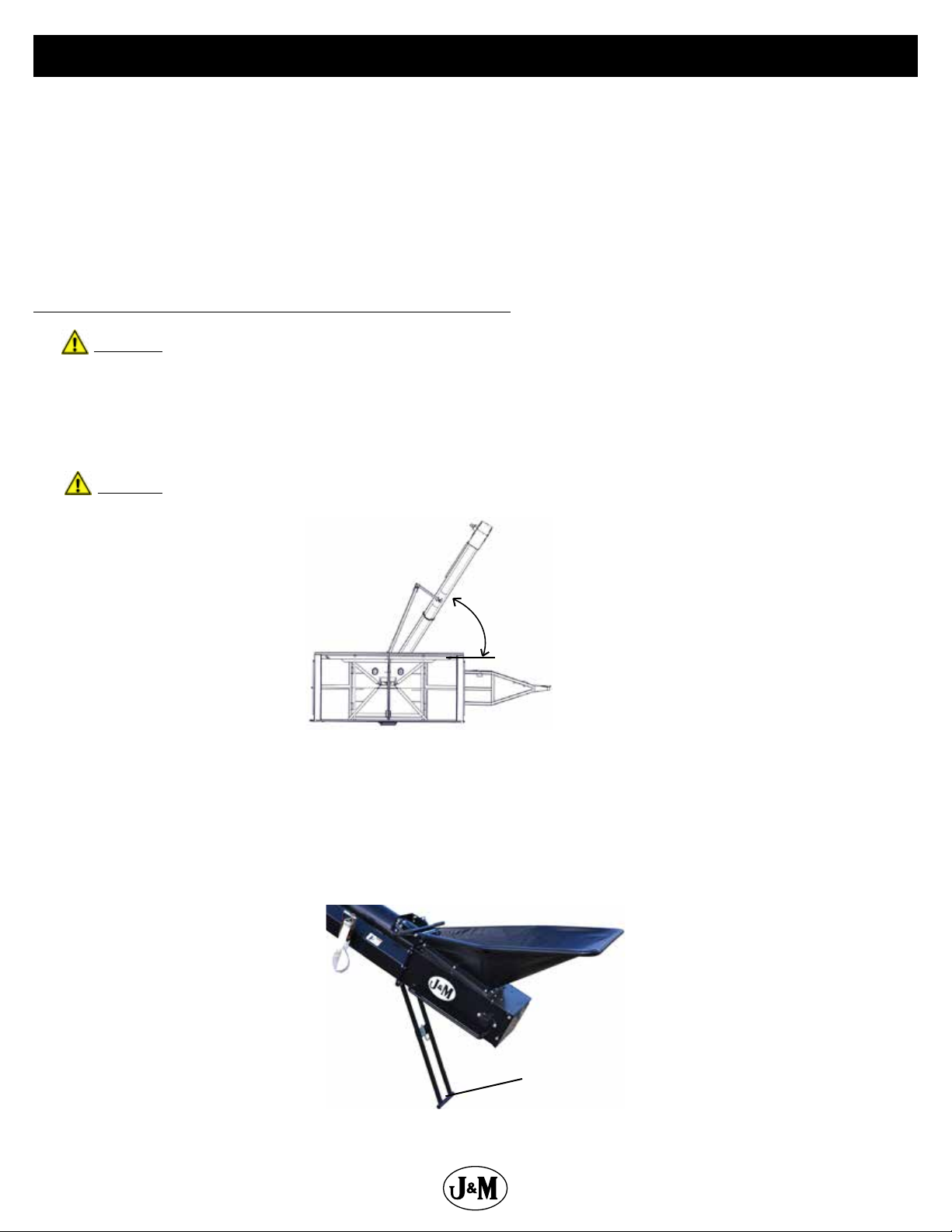
1. Move the jack to the horizontal position before transporting.
2. Ensure the conveyor is in the conveyor rest and strapped down.
3. Ensure the collapsible hopper is in the down position with the vinyl hopper cover applied.
4. When transporting the SpeedTender on public roads, it is recommended to have the
conveyor in the forward-facing position. The rearward-facing position may not comply
with state law for lighting and marking requirements.
WARNING: Travel at a safe speed to maintain complete control of towing vehicle and SpeedTender at all times.
11
Page 12
Operations
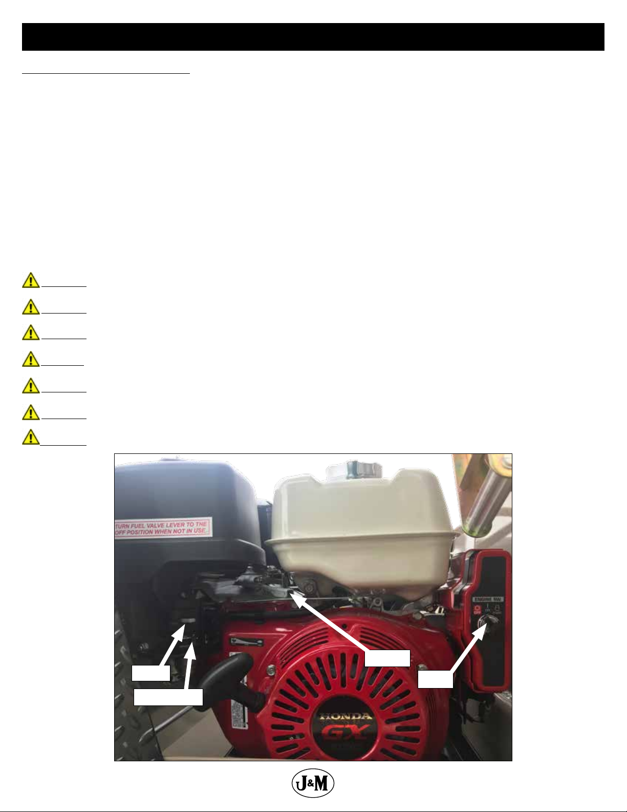
Hydraulic Power Unit Operation
Ensure all ttings and hardware are in proper operating condition. Replace if worn or broken. Check engine uid levels and sight gauge
on reservoir for proper operating levels.
1. Slide the fuel shut-o lever to the “ON” position.
2. Slide choke to the “ON” position.
3. Turn the key to the start position. Once engine starts, release key.
4. After starting, allow the engine to warm up. Slide choke to the “OFF” position and increase throttle speed.
5. The engine must throttle at, or above 80% throttle for 3 seconds to begin charge. After the 3 seconds at 80% throttle the battery will
continue to charge until the engine is turned o.
6. To turn the engine o, slide the fuel shut-o lever to the “OFF” position.
7. Turn key o.
NOTE: In extremely cold weather, it is best to allow engine and hydraulics to warm up before increasing throttle speed.
NOTE: If a hydraulic leak appears, turn o immediately and take appropriate action.
NOTE: See engine operator’s manual for more details on upkeep and service.
WARNING: Purge hydraulic system of air before operating SpeedTender to prevent serious injury or death.
WARNING: Wear proper hand and eye protection when searching for leaks. Use wood or cardboard instead of hands.
WARNING: Explosive fuel can cause res and severe burns. Stop engine before lling fuel tank.
WARNING: Carbon monoxide can cause severe nausea, fainting or death. Do not operate engine in an enclosed or conned area.
WARNING: Hot parts can cause severe burns. Do not touch engine while operating or just after stopping.
WARNING: Acid from battery can cause res and severe acid burns. Make sure to charge battery in well-ventilated area.
WARNING: Make sure to relieve hydraulic pressure before working on hydraulic system.
12
Choke
Fuel Shut-o
Throttle
Key
Page 13
Operations
Field Operation
WARNING: The SpeedTender must be hooked to the towing vehicle during loading and unloading.
1. Position the SpeedTender next to the planter/drill so the conveyor will reach the planter box.
2. Release the ratchet strap from the conveyor.
3. Start the hydraulic power unit and increase throttle speed. Allow hydraulic uid to warm up.
4. Raise the conveyor o the conveyor rest using the handheld control.
Conveyor
Conveyor Rest
Ratchet Strap
WARNING: When operating the hydraulic swing option, do not stand in the operating range of the conveyor.
Operating Range
5. Check to make sure the hopper is in the up position.
Hopper Up
6. Open door on SpeedTender using the supplied remote.
WARNING: Empty the rear compartment rst to prevent the chance of ipping the SpeedTender.
13
Page 14
Operations
7. Use the handheld controller or wireless remote to start the conveyor.
8. Fill the planter/drill to desired level then repeat.
NOTE: Adjusting engine throttle will regulate conveyor speed.
9. Close door on SpeedTender before the last planter seed box is full so you can completely empty collapsible hopper and conveyor.
10. Position conveyor above conveyor rest and lower to allow its full weight on the conveyor rest.
11. Lock down conveyor using the ratchet strap.
12. Collapse the hopper to the down position and apply the vinyl hopper cover.
13. Slide the fuel shut-o lever to the “OFF” position. This will allow the engine to shuto by running out of gas.
14. Turn the key to the “OFF” position.
Filling SpeedTender From Another Wagon or Bulk Container
WARNING: The SpeedTender must be hooked to the towing vehicle during loading and unloading.
1. Release ratchet strap from conveyor.
2. Start the hydraulic power unit and increase throttle speed. Allow hydraulic uid to warm up.
NOTE: Make sure collapsible hopper is in the down position.
3. Raise the conveyor o the conveyor rest using the handheld control.
CAUTION: If you are parked on an incline, the conveyor may swing freely. It is advised that you do not use SpeedTender
on uneven ground.
4. Rotate the conveyor to 45°.
5. Lower the conveyor so you can remove the telescoping spout from the discharge end of the conveyor.
6. Remove pins and raise up both handles to release ball from latch system. Slide the ball away from the middle of the tender, then
swing the collapsible hopper end out from under the SpeedTender shell.
7. Position the discharge end over the SpeedTender.
8. Lock the conveyor in place. The conveyor is equipped with a stand. (It is recommended for use whenever possible to maximize
conveyor performance and for easier access to discharge point on bulk seed containers).
45°
Conveyor
Stand
14
Page 15
Operations
9. Lock collapsible hopper in the up position.
10. Position the wagon or bulk seed container over the collapsible hopper.
11. Use the handheld controller or wireless remote to start the conveyor.
12. Fill the SpeedTender to desired level.
WARNING: Fill the front compartment rst to help prevent the chance of ipping.
13. Run the conveyor until the collapsible hopper is empty.
14. When nished loading seed into the SpeedTender, move the wagon or bulk seed container away from conveyor.
15. Collapse the hopper to the down position and apply the vinyl hopper cover.
16. With the conveyor at a 45° angle, swing the conveyor hopper back under the tank and slide ball back into latch system. Replace both pins
on latch handles.
17. Position conveyor above the conveyor rest and lower to allow its full weight on the rest.
18. Lock down conveyor using the ratchet strap.
19. Slide the fuel shut-o lever to the “OFF” position. This will allow the engine to shuto by running out of gas.
20. Turn the key to the “OFF” position.
Cleaning out Collapsible Hopper and Conveyor
WARNING: The SpeedTender must be hooked to the towing vehicle during loading and unloading.
1. Release strap from conveyor.
2. Start the hydraulic power unit and increase throttle speed. Allow hydraulic uid to warm up if it is cold outside.
NOTE: Ensure collapsible hopper is in the down position.
3. Raise the conveyor out of conveyor rest using the handheld control.
CAUTION: If you are parked on an incline, the conveyor may swing freely. Use of the SpeedTender on uneven ground is
not advised.
4. Rotate the conveyor to 45°.
5. Lower the conveyor so you can remove the telescoping spout from the discharge end of the conveyor.
6. Swing the collapsible hopper end out from under the SpeedTender shell.
7. Place the collapsible hopper in the up position.
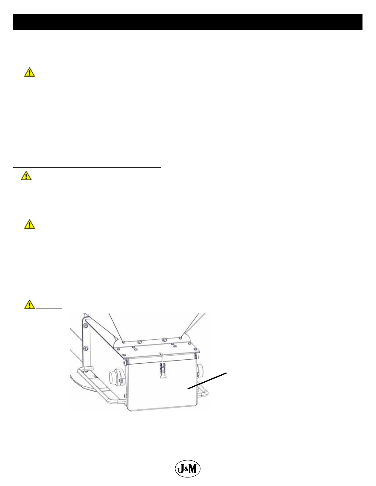
8. With the discharge end lower than the collapsible hopper end, place the discharge end into a 5 gallon bucket. Using the handheld
controller, start the conveyor and run until completely empty.
9. Lower the collapsible hopper end back down to the ground. This will allow you to open the conveyor clean out door.
CAUTION: Ensure all power is shut o before opening conveyor clean out door.
Conveyor Clean
Out Door
10. Place collapsible hopper in the down position
11. With the conveyor at a 45° angle, swing the conveyor hopper back under the tank and slide ball back into latch system. Replace both
pins on latch handles.
15
Page 16
Operations
12. Position conveyor above conveyor rest and lower to allow its full weight on the conveyor rest.
13. Tighten strap and ensure it is secured.
14. Ensure the collapsible hopper is in the down position and apply the vinyl hopper cover.
15. Slide the fuel shut-o lever to the “OFF” position. This will allow the engine to shuto by running out of gas.
16. Turn the key to the “OFF” position.
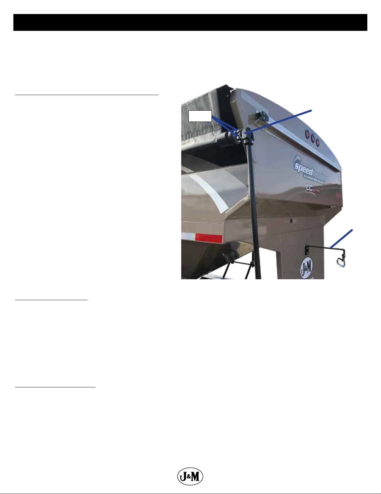
Adjusting the Tarp Tension in Hanger Bracket
1. Fully unroll the tarp as shown on the right.
2. Remove the two bolts that hold the tarp u-joint on the
splined shaft.
3. Remove the u-joint from the splined shaft.
4. Rotate u-joint and handle three or four spline teeth.
5. NOTE: Rotate clockwise to tighten the tarp or
counterclockwise to loosen it.
6. Slide the u-joint and handle back onto the spline shaft.
7. Replace and tighten the two bolts.
Bolts
U-Joint
Hanger
Bracket
Basic Scale Operations
1. Turn the scale “ON” by pressing the on/o button. The display shows “Hello” then the current weight value is displayed.
2. Press G/N to access the gross mode. (Live scale weight is displayed in the G/N weighing mode.)
3. In the gross mode, press the ZERO/CLEAR key to zero the indicator when the SpeedTender is empty.
4. After initial amount is placed on the scale, press the TARE Key. (Weight is tared o and goes into net mode, showing weight).
5. Load or unload material as needed (Shows + when loading and a – value when unloading).
6. When the display reaches the proper amount, stop loading or unloading.
7. Repeat steps 2 through 4 until complete.
NOTE: For more information, refer to the scale manual.
Basic Remote Operations
1. For instructions on pairing your remote or setting up the auto dispense feature, see the instructions decal on the inside of the scale
display box.
2. When using the optional Intercomp WC3-D remote, additional instructions can also be found in the Intercomp Operator’s Manual
provided with your SpeedTender.
16
Page 17

General Service
Daily Service (5 -10 Hours of Use)
NOTE: J&M recommends the following service to be performed daily (every 5-10 hours of use)
1. Grease the conveyor bearings every 10 hours. Use only two pumps of grease per bearing.
NOTE: Excess lubrication of these bearings will result in premature failure.
NOTE: The conveyor has four bearing that need greased (two at each end). See “Conveyor Service” on page 21.
2. Check your belt for proper tracking every 10 hours of use and before every season. For steps to properly track your belt see ”Adjusting Conveyor
Belt Tracking” on page 23.
NOTE: When checking the belt for tracking you should empty out the conveyor clean out door. See “Cleaning out Collapsible
Hopper and Conveyor” on page 15.
3. Check hydraulic oil level.
4. Inspect for oil leaks and repair as appropriate.
5. Check all hoses, ttings, bolts, and hardware to make sure that they are secure and properly tightened.
6. Check engine oil level. See engine operator’s manual for details on oil levels, oil types and service intervals.
7. Check SpeedTender brakes and lights before towing.
8. Check the SpeedTender periodically for cracks in welds and for other structural damage. Fix cracked welds immediately.
NOTE: Failure to have cracked welds xed immediately could result in extensive damage to the SpeedTender and greatly
reduce its life.
9. Ensure tires are properly inated. Tire care guidelines can be found in “Tire Service” on page 19.
10. Ensure wheel lug nuts are properly torqued. See “Bolt Torque Specications” on page 10.
11. Ensure the conveyor hopper guard is in place. Do not remove.
12. Clean out the conveyor at the end of every day of use.
End of the Year Service
IMPORTANT: When the SpeedTender is not going to be used for a length of time, J&M recommends that you store the
SpeedTender in a dry, protected place. Leaving your SpeedTender outside and open to the weather will shorten its life.
1. Grease the conveyor bearings. Use only two pumps of grease per bearing.
NOTE: Excess lubrication of these bearings will result in premature failure.
NOTE: The conveyor has four bearing that need greased (two at each end). See “Conveyor Service” on page 21.
2. Grease pivot points on boom arm before storage.
3. The wheel bearings need to be cleaned, inspected, repacked, and adjusted. Use a number 2 wheel bearing grease to repack the bearings.
4. Inspect and service the brakes (magnets and shoes). They must be changed when they become worn or scored to prevent
inadequate vehicle braking. Clean the backing plate, magnet arm, magnet, and brake shoes. Make certain all the parts removed
are replaced in the same brake and drum assembly. Inspect the magnet arm for any loose or worn parts. Check shoe return springs,
hold down springs, and adjuster springs for stretching or deformation and replace if required.
5. If equipped with talc, be sure to empty talc box entirely and run the talc auger to completely empty talc from the auger pipe.
6. Ensure wheel lug nuts are properly torqued. See “Bolt Torque Specications” on page 10.
7. Ensure tires are properly inated. Tire care guidelines can be found in “Tire Service” on page 19.
8. Remove all seed from inside the seed tanks.
9. Clean out the conveyor at the end of every season. See “Cleaning out Collapsible Hopper and Conveyor” on page 15.
10. Tension and track the conveyor belt. See “Adjusting Conveyor Belt Tracking” on page 23.
11. Check the SpeedTender periodically for cracks in welds and for other structural damage. Have cracked welds xed immediately.
NOTE: Failure to have cracked welds xed immediately could result in extensive damage to the SpeedTender and greatly
reduce its life.
12. Check hydraulic hoses for wear and replace if needed.
13. Ensure the conveyor hopper guard is in place.
14. Remove battery from the SpeedTender and place in a cool, dry place.
NOTE: Attaching a trickle charger to the battery will help ensure a long life for your battery.
IMPORTANT: Be sure to disconnect the scales from the battery before charging.
15. Change hydraulic oil lter element with either a NAPA 1552 or a FRAM P1654A Filter.
16. Top o hydraulic oil tank with good quality hydraulic AW 32 oil.
NOTE: If the hydraulic oil appears to be “milky” in color, it should be changed immediately. Otherwise, the hydraulic oil should
be changed every 2-3 years. If the environment is extremely dusty or dirty the hydraulic oil should be changed more often.
17. Check motor oil level. See engine operator’s manual for details on oil levels, oil types, and service intervals.
18. Retract all hydraulic cylinders to prevent the piston rods from rusting.
19. Touch up spots where paint has worn away (use good quality primer paint - especially before applying graphite paint to the inside
of the shell).
17
Page 18

General Service
Removing From Storage
1. Grease the conveyor bearings. Use only two pumps of grease per bearing.
NOTE: Excess lubrication of these bearings will result in premature failure.
NOTE: The conveyor has four bearings that need greased (two at each end). See “Conveyor Service” on page 21.
2. Grease pivot points on boom arm.
3. Ensure wheel lug nuts are properly torqued. See “Bolt Torque Specications” on page 10.
4. Ensure tires are properly inated. Tire care guidelines can be found in “Tire Service” on page 19.
5. Check your belt for proper tracking every 10 hours of use and before every season. For steps to properly track your belt see ”Adjusting Conveyor
Belt Tracking” on page 23.
NOTE: When checking the belt for tracking you should empty out the conveyor clean out door. See “Cleaning out Collapsible
Hopper and Conveyor” on page 15.
6. Check oil level.
7. Inspect for hydraulic oil leaks and repair as appropriate.
8. Check all hoses, ttings, bolts, and hardware to ensure they are secure and properly tightened.
9. Check engine oil level. See engine operator’s manual for details on oil levels, oil types, and service intervals.
10. Check SpeedTender brakes and lights before each time you tow.
11. Ensure the conveyor hopper guard is in place.
12. Reattach battery and check to ensure it is fully charged.
IMPORTANT: Be sure to disconnect the scales from the battery before charging.
Hydraulic Power Service
Daily (every 5 hours of use):
1. Check oil level.
2. Inspect for oil leaks and repair as necessary.
3. Check all hoses, ttings, bolts and hardware to ensure they are secure and properly tightened.
4. Check motor oil level. See engine operator’s manual for details on oil levels, oil types, and service intervals.
Once per season (every 20-25 hours of use):
Change hydraulic oil lter element with either a NAPA 1552 or a FRAM P1654A Filter.
Every two to three years (every 75-80 hours of use):
Drain oil reservoir and rell with clean, good quality hydraulic AW 32 oil. (It is not recommended to rell with tractor hydraulic oil).
Replacing hydraulic parts:
Refer to “Hydraulics Schematic for Aluminum Valve” on page 54 or “Hydraulics Schematic for Black Intercomp Valve” on page 56 for
proper part description and part number for replacement.
Purge air from system as follows:
1. Disconnect the rod end clevis of all cylinders in a circuit and block up cylinders so the rod can completely extend and retract without
contacting any other components.
2. Pressurize the system and maintain system at full pressure for at least 5 seconds after cylinder rods stop moving. Check that all
cylinders have fully extended or retracted.
3. Check hydraulic reservoir and rell as needed.
4. Pressurize system again to reverse the motion of step 2. Maintain pressure on system for at least 5 seconds after cylinder rods stop
moving. Check that cylinders have fully extended or retracted.
5. Check for hydraulic leaks using cardboard or wood.
6. Repeat steps 2, 3, 4 and 5 (3 to 4 times).
7. Depressurize hydraulic system and connect cylinder rod clevises to their mating lugs.
18
Page 19
Tire Service
Tire Pressure
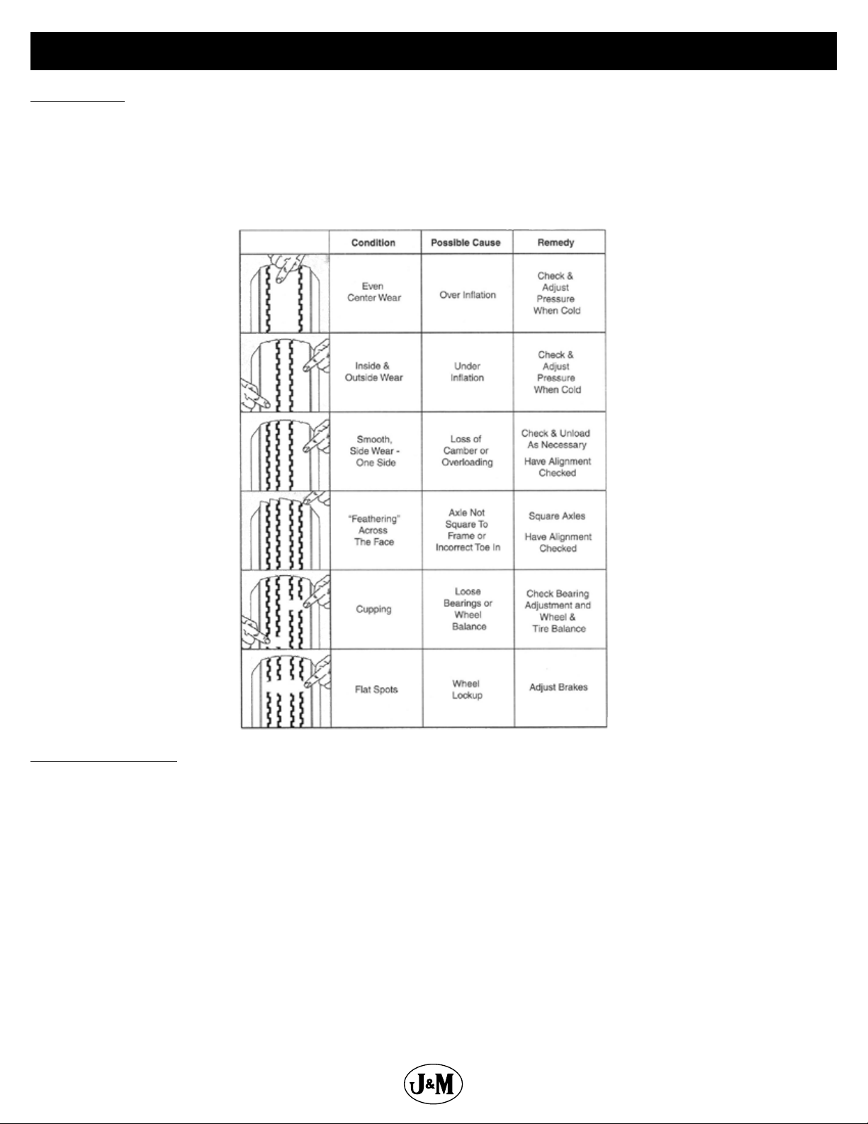
The following is to be used as a general guide for tire ination. Figures can vary depending on specic brand of tire used. It is important
that tires are inspected before and after unit is loaded. Start with the minimum pressure indicated. The tire should stand up with no
side wall buckling or distress as tire rolls. Do not exceed maximum recommended tire pressure. 235-85-R16 tires are standard on the
SpeedTender and should be inated to 80 psi. J&M also recommends rotating your tires front to back (not side to side) every 1,200
miles or 12 months (whichever comes rst) for longer tire life. The image below is a troubleshooting chart used to ensure the tires wear
evenly.
Tightening Lug Nuts
Torque 9/16”-18 lug nuts on wheels to 170 ft-lbs after the rst 10, 25, and 50 miles of driving, then recheck torque every 50 hours or every
year, whichever comes rst. Failure to do so may damage wheel nut seats. Once seats are damaged, it will become impossible to keep
nuts tight.
19
Page 20

Wheel Bearing Service
Clean, inspect, and repack the wheel bearings every 12 months or 12,000 miles. Use a number 2 wheel bearing grease to repack the
bearings.
Bearing Inspection and Service:
1. Jack up SpeedTender.
2. Remove wheel lug nuts.
3. Remove wheel from hub.
4. Remove grease cap.
NOTE: Be careful not to dent or cut a hole in grease cap.
5. Remove the cotter pin, nut, and washer.
6. Wiggle the hub to take the outer wheel bearing out.
7. Pull hub assembly straight o the axle. If you want to reuse the grease seal, (which is not recommended), be careful to support the
weight of the hub so that the end of the axle does not ruin the rubber part of the grease seal.
8. To remove the inner bearing, you must remove the grease seal.
9. Remove inner bearing.
10. Wash all grease and oil from the bearing cone using a suitable solvent. Dry the bearing with a clean, lint-free cloth and inspect each
roller completely. If any pitting, scalding, or corrosion is present, then the bearing must be replaced. The bearing cups inside the
hub must be inspected.
NOTE: Bearings must always be replaced in sets of a cone and a cup.
11. Repack inner bearing with new grease.
A. Place a moderate amount of grease in the palm of one hand.
B. Hold the inner bearing, large side down, in your other hand.
C. Using the edge of the bearing like an ice cream scoop, work it in until you see fresh grease come out of the top side of the
bearing.
D. Rotate 1/8 of a turn and repeat until the whole bearing is full of fresh grease.
12. Place the inner bearing in the back of the wheel hub and add a liberal dose of grease.
13. Position the new wheel seal in its recess and lightly set it with a hammer.
NOTE: Be careful to not deform the metal part of the seal.
14. Slide the hub assembly onto the spindle and push it back into position.
15. Grease the outer bearing by hand, repeating the procedure used with the inner bearing in step 11.
16. Slide the outer bearing and the spindle washer onto the spindle and into the hub recess.
17. Install and bottom out the spindle nut, then back it o 1/4 turn.
18. Reinstall the spindle nut and replace the cotter pin with a new one.
NOTE: If the castle nut does not line up with the hole in the spindle, then loosen the nut slightly until it does.
19. Pack the bearing cap with fresh grease and lightly drive it into the hub recess with a hammer.
20. Reinstall the wheel onto the hub and torque the wheel lug nuts. See “Bolt Torque Specications” on page 10.
Bearing cup replacement:
1. Place the hub on a at work surface with the cup to be replaced on the bottom side.
2. Using a brass drift punch, carefully tap around the small diameter end of the cup to drive it out.
3. After cleaning the hub bore area, replace the cup by tapping it with the brass drift punch. Be sure the cup is seated all the way up
against the retaining shoulder in the hub.
20
Page 21

Conveyor Service
Grease Conveyor Bearings
Grease the conveyor bearings every 10 hours of operation and before storage. Use only two pumps of grease per bearing.
NOTE: Excess lubrication of these bearings will result in premature failure.
NOTE: The conveyor has four bearings that need grease (two at each end).
Grease Point
Grease Swing Arm
Grease pivot points on boom arm every 50 hours and before storage.
Grease Points
21
Page 22

Conveyor Service
Conveyor belt must run in the center of the pulley at both the discharge end and the collapsible hopper end. Failure to do so will lead
to unnecessary wear and shortening of belt life. We recommend that you check your belt for proper tracking every 10 hours of use and
before every season.
Checking the belt tracking at collapsible hopper end:
1. Open clean out door located under collapsible hopper to see if the belt is centered on the pulley.
2. If the belt tracking is centered, close the clean out door. If tracking needs adjustment, “Adjusting Conveyor Belt Tracking” on the next
page.
Checking the belt tracking at discharge end:
1. Remove the 12 bolts located at the discharge end (as displayed in the diagram below).
2. Remove the discharge pan and rubber discharge pan to see if the belt is centered on the pulley.
3. If the belt tracking is centered, reinstall the head pan. If tracking needs adjustment, see “Adjusting Conveyor Belt Tracking” on the
next page.
Discharge Pan
Bearing
Mounting Plate
Jam Nut
Adjustment Bolt
Remove
Loosen these
bolts when adjusting belt tension.
Procedure same for each side.
A
Remove
Conveyor
Clean Out Door
B
22
Measurements A & B need to be the same.
Page 23

Conveyor Service
Adjusting Conveyor Belt Tracking
1. Loosen, but do not remove, the four bolts on the two bearing mounting plates located at the collapsible hopper end of the
conveyor (as shown in the picture below).
NOTE: Only adjust conveyor in normal position, do not adjust in self-ll position.
2. Operate the conveyor at a slow speed.
CAUTION: Keep hands and clothing away from moving parts.
3. Loosen jam nut on adjustment bolt.
4. Tighten the adjustment bolt slowly until belt is running in the center of the pulley.
NOTE: Do not loosen the adjustment bolt.
5. Tighten all bolts on bearing mounting plate as well as the jam nuts on the adjustment bolts.
6. Repeat at discharge end.
7. When belt is running in center of the pulley on both ends of conveyor, allow the SpeedTender to run for 10 minutes and recheck
the belt for proper tracking.
Jam Nut
Bearing
Mounting Plate
Adjustment Bolt
Jam Nut
Loosen these bolts when adjusting
belt tension. Typical each side.
Belt Tensioning
NOTE: You need to adjust your belt tension at least once a year.
1. Remove the head pan and head pan gasket.
2. Loosen, but do not remove, the four bolts on the two bearing mounting plates located at the discharge end of the conveyor.
3. Loosen jam nut on adjustment bolt at discharge end.
4. Torque threaded adjustment bolt to 23 ft-lbs.
5. Operate the conveyor at a slow speed.
CAUTION: Keep hands and clothing away from moving parts.
6. If the belt is tracking properly go to next step. If tracking needs adjustment, see “Adjusting Conveyor Belt Tracking” above.
7. Open the clean out door located under collapsible hopper to see if the belt is centered on the pulley. If the tracking is centered, close
the clean out door, tighten all hardware and go to next step. If tracking is o, see “Adjusting Conveyor Belt Tracking” above.
8. Run the belt at medium speed for 10 minutes and recheck the tracking at both the discharge and collapsible hopper end. If the
belt is still tracking in the center of both pulleys, reinstall the head pan. If tracking needs adjustment, see “Adjusting Conveyor Belt
Tracking” above.
23
Page 24

Brakes Service
The SpeedTender is equipped with electric brakes. They need to be inspected and serviced immediately if a loss of performance is
experienced. You need to service your SpeedTender brakes at least once a year with normal use.
How to use your electric brakes properly:
Your SpeedTender brakes are designed to work in synchronization with your tow vehicle brakes. Never use your tow vehicle or
SpeedTender brakes alone to stop the combined load.
Your SpeedTender and tow vehicle will seldom have the correct amperage ow to the brake magnets to give you comfortable, safe
braking unless you make proper brake system adjustments. Changing trailer load and driving conditions, as well as uneven alternator
and battery output, can mean unstable current ow to your brake magnets. It is therefore imperative that you maintain and adjust your
brakes as set forth in this manual, use a properly modulated brake controller, and perform the synchronization procedure noted below.
In addition to the synchronization adjustment detailed below, electric brake controllers provide a modulation function that varies the
current to the electric brakes with the pressure on the brake pedal or amount of deceleration of the tow vehicle. It is important that your
brake controller provide approximately 2 volts to the braking system when the brake pedal is rst depressed and gradually increases
the voltage to 12 volts as brake pedal pressure is increased. If the controller “jumps” immediately to a high voltage output, even during a
gradual stop, then the electric brakes will always be fully energized and will result in harsh brakes and potential wheel lockup.
To synchronize:
To ensure safe brake performance and synchronization, read the brake controller manufacturer’s instruction completely before
performing the synchronization procedure.
Make several hard stops from 20 mph on a dry, paved road that is free of sand and gravel. If the SpeedTender brakes lock and slide,
decrease the gain setting on the controller. If they do not slide, slightly increase the gain setting, Adjust the controller just to the point of
impending brake lockup and wheel skid.
How to adjust electric brakes:
1. Park the SpeedTender on rm and level ground.
2. Block the trailer tires on the opposite side securely so that no forward or rearward movement is possible.
3. Jack up the SpeedTender.
4. Secure the front and rear of the trailer on jack stands of adequate capacity.
5. At the back of the wheel, on the brake backing plate, there is a small rubber plug near the bottom of the backing plate. Pry out this
plug to give access to the star wheel adjuster.
6. Insert the brake adjuster tool and maneuver it so that the tool engages with the teeth in the star wheel. The star wheel looks like a
gear with exposed teeth on the perimeter.
7. Turn the adjuster until the brake locks up (you can no longer rotate the wheel by hand). This centers the brake shoes on the brake
drum in the correct position.
8. Back o the star wheel 8-10 clicks or as specied by the manufacturer. The wheel should spin freely with no apparent drag to slow
it down. A slight scraping noise is normal as the wheel turns.
9. Repeat this procedure for all the wheels.
When to adjust brakes:
1. After the rst 200 miles of operating when the brake shoes and drums have “seated.”
2. At 3,000 mile intervals or once a year, whichever comes rst.
Brake Cleaning and Inspection:
Your SpeedTender brakes must be inspected and serviced at yearly intervals, (or more often as use and performance requires). Magnets
and shoes must be changed when they become worn or scored, which causes inadequate vehicle braking. Clean the backing plate,
magnet arm, magnet, and brake shoes. Make certain all the parts removed are replaced in the same brake and drum assembly. Inspect
the magnet arm for any loose or worn parts. Check shoe return springs, hold down springs, and adjuster springs for stretching or
deformation and replace if required.
24
Page 25

Brakes Service
Brake Shoe and Lining Inspection:
A simple visual inspection of your brake linings will tell if they are usable. Replacement is necessary if the lining is worn (to within 1/16” or
less), contaminated with grease or oil, or abnormally scored or gouged. Hairline heat cracks are normal in bonded linings and should not
be cause for concern. When replacement is necessary, it is important to replace both shoes on each brake and both brakes of the same
axle. This will help retain the “balance” of your brakes.
Acceptable
Hairline Cracks
Replacing Brake Linings:
1. Remove the brake shoe retract spring.
2. Remove the shoe hold down assembly by holding the back of the pin with one hand and pushing against the spring and twisting
with a hold down spring tool until the cup is released.
3. Remove both shoes together leaving the adjuster assembly and spring intact.
4. Clean the backing plate and lever arm.
5. Inspect magnet arm for any loose or worn parts.
6. Replace springs that are broken, bent, or weak.
7. Apply a light lm of lubricant to the anchor pin and shoe rest pads & backing plate areas that are in contact with the lever arm.
8. Attach the adjuster screw and spring to the new brake shoes. The star wheel and adjuster must be positioned as before.
9. Install the new shoes on the backing plate and reinstall shoe retract spring.
After replacement of brake shoes and linings, the brake must be re-burnished to seat in the new components. This should be done by
applying the brakes 20-30 times from an initial speed of 40 mph, slowing the vehicle to 20 mph. Allow ample time for brakes to cool
between applications. This procedure allows the brake shoes to seat into the drum surface.
Brake Lubrication:
Before reassembling, apply a light lm of lubrication or similar grease, or anti-seize compound on the brake anchor pin, the actuating
arm bushing and pin, and the areas of the backing plate that are in contact with the brake shoes and magnet lever arm. Apply a light lm
of grease on the actuating block mounted on the actuating arm.
Troubleshooting:
Mechanical causes are ordinarily obvious, bent or broken parts, worn out linings or magnets, seized lever arms or shoes, scored drums,
loose parts, etc. Most electric brake malfunctions that cannot be corrected by either brake adjustments or synchronization adjustments
can generally be traced to electrical system failure. Voltmeter and ammeter are essential tools for proper troubleshooting of electric
brakes.
How to Measure Voltage:
System voltage is measured at the magnets. Connect the voltmeter to the two magnet lead wires at any brake. This may be
accomplished by using a pin probe inserted through the insulation of the wires dropping down from the chassis or by cutting the
wires. The engine of the towing vehicle should be running when checking the voltage (so that a low battery will not aect the
readings).
Brake Magnet Inspection:
Your electric brakes are equipped with high quality electromagnets that are designed to provide the proper force and friction. Your
magnets should be inspected and replaced if worn unevenly or abnormally (as shown below). Even if wear is normal as indicated by your
straightedge, the magnets should be replaced if any part of the magnet coil has become visible through the friction material facing of
magnet. It is also recommended that the drum armature surface be re-faced when replacing magnets. Magnets should also be replaced
in pairs - both sides of an axle.
Straight Edge
Abnormal Wear
(Replace)
Normal Wear
25
Page 26

Brakes Service
Voltage in the system should begin at 0 volts. As the controller bar is slowly actuated, the voltage should gradually increase to
approximately 12 volts, which is referred to as modulation. No modulation means when the controller begins to apply voltage to brakes,
it applies an immediate high voltage, which causes the brakes to apply instantaneous maximum power.
The threshold voltage of a controller is the voltage applied to the brakes when the controller rst turns on. The lower the threshold
voltage, the smoother the brakes will operate. Threshold voltage in excess of 2 volts (quite often found in heavy duty controllers) can
cause grabbing, resulting in harsh braking.
How to Measure Amperage:
System amperage is the amperage being drawn by all brakes on the trailer. The engine of the towing vehicle should be running when
checking amperage.
Measure system amperage on the blue wire of the controller, which is the output to the brakes. The blue wire must be disconnected and
the amp meter put in series into the line. System amperage draw should be as noted in the table below. Make sure your ammeter has
sucient capacity and note polarity to prevent damaging your amp meter.
Brake Size Amps/Magnet Two Brakes Four Brakes Six Brakes Magnet Ohms
12 X 2 3.0 6.0 12.0 18.0 3.2
Replacing brake magnet:
1. Orient the magnet over the lever arm post such that the magnet leads are in the correct position for routing.
2. Push the magnet over the lever arm post by compressing the magnet spring between the magnet and the lever arm.
3. Insert the magnet clip in the slot of the magnet. Be sure to orient the magnet clip so it will “snap” into place.
4. Press down on the magnet and install the magnet clip.
5. Be sure that the magnet moves up and down freely on the lever arm post.
6. Route the wiring in the same manner noted on removal. Be sure that wires cannot bind, pinch, or rub. Manually actuate lever arm to
ensure there is no interference.
7. Install strain relief bushing, allowing enough slack in the wiring to allow the lever arm to move without straining the wires. Be sure
the wire cannot come in contact with the armature.
8. Connect the magnet leads to the trailer wiring harness and then reinstall hub and drum.
Brake Drum Inspection:
There are two areas of the brake drum that are subject to wear and require inspection. These two areas are the drum surface where the
brake shoes make contact during stopping and the armature surface where the magnet contacts (only in electric brakes).
The drum surface should be inspected for excessive wear or heavy scoring. If worn more than .020” oversized, or if the drum has worn out
of round by more than .015”, then the drum surface should be turned. If scoring or other wear is greater than .090” on the diameter, the
drum must be replaced. When turning the drum surface, the maximum re-bore diameter for a 12” brake drum is 12.090”
The machined inner surface of the brake drum that contacts the brake magnet is called the armature surface. If the armature surface is
scored or worn unevenly, it should be refaced to a 120 micro inch nish by removing not more than .030” of material. To ensure proper
contact between the armature face and the magnet face, the magnets should be replaced whenever the armature surface is refaced. The
armature surface should be refaced whenever the magnets are replaced.
26
Page 27

Troubleshooting
Problems Solutions
Unit sways during travel a. Check tire pressure.
b. Check tow vehicle for loosened hitch parts.
c. Check tow vehicle’s hitch height.
d. Reduce towing speed.
e. Check wheel lug nuts.
f. Check wheel bearings for adjustment (see ”Wheel Bearing Service” on page 20).
Tires show excessive wear a. Check tire pressure.
b. Rotate tires (see “Tire Service” on page 19).
c. Check wheel bearings for adjustment (see “Wheel Bearing Service” on page 20).
Wheel makes grinding or squeaking noise a. Service wheel bearings (see “Wheel Bearing Service” on page 20).
Noisy when brakes are being applied a. Properly adjust brakes.
b. Replace any weak or broken springs in brakes.
c. Replace the brake linings if excessively worn or contaminated.
d. Check wheel bearings for adjustment (see “Wheel Bearing Service” on page 20).
No brakes a. Properly adjust brakes.
b. Check for short in electric circuit.
c. Replace any brake magnets that are worn or defective.
Weak brakes a. Properly adjust brakes.
b. Replace any excessively worn or contaminated linings.
c. Check for short in electric circuit.
d. Replace bent backing plate.
Dragging brakes a. Properly adjust brakes.
b. Replace any weak or broken springs in brakes.
Locking brakes a. Replace any weak or broken springs in brakes.
b. Replace any excessively worn or contaminated linings.
Grabbing brakes a. Replace any excessively worn or contaminated linings.
Surging brakes a. Trailer is not adequately grounded.
Belt is not moving - Hydraulic pump is not
producing sucient pressure or volume to belt
motor
Belt is not moving - Obstructed conveyor a. Ensure conveyor is not clogged.
Belt has insucient output speed or RPM -
Hydraulic pump is not producing sucient
pressure or volume to belt motor
Belt has insucient output speed or RPM - Belt is
slipping
Belt has insucient output speed or RPM - Air in
hydraulic system
Belt has insucient output speed or RPM - Leak in
motor, valve body, or bypass valves
Excessive wear to belt edge - Tracking is o a. Adjust belt tension and tracking (see “Adjusting Conveyor Belt Tracking” on page 23).
a. Check for pinched or leaking hydraulic line.
b. Allow hydraulic oil to warm up.
c. Increase engine RPM.
d. Charge battery or plug in to tow vehicle.
e. Hydraulic uid level low.
f. Hydraulic lter clogged.
g. Check for proper oil viscosity.
h. Check hydraulic output pressure.
a. Check for pinched or leaking hydraulic lines.
b. Allow hydraulic oil to warm up.
c. Increase engine RPM.
d. Hydraulic uid level low.
e. Hydraulic lter clogged.
f. Check for proper oil viscosity.
g. Repair or replace worn out pump.
a. Adjust belt tension and tracking (see “Adjusting Conveyor Belt Tracking” on page 23).
b. Check telescoping spout and conveyor for a clog.
c. Remove material from clean out door.
a. Bleed air out of hydraulic system and ll reservoir (see “Hydraulic Power Service” on page 18).
b. Look for leaking or cracked ttings.
a. Replace or repair motor, valve body, or bypass valves.
b. Check for proper oil viscosity.
c. Clean and lubricate the brake assemblies.
27
Page 28

Troubleshooting
Problems Solutions
Excessive wear to belt edge - Rubber skirting is
worn or out of place
Swing arm will not move up or down - Engine RPM
slow
Swing arm will not move up or down - Hydraulic
pump is not producing sucient pressure or
volume to hydraulic cylinder
Hydraulic unit squeals a. Check sight glass on hydraulic unit reservoir and ll if necessary.
Hydraulic unit has poor performance at high RPM a. Clean pressure relief in control valve or replace.
a. Replace rubber skirting.
b. Adjust rubber skirting.
a. Increase engine RPM.
a. Check for pinched or leaking hydraulic lines.
b. Allow hydraulic oil to warm up.
c. Increase engine RPM.
d. Hydraulic uid level low.
e. Hydraulic lter clogged.
f. Check for proper oil viscosity.
g. Check if hydraulic pump is worn out.
h. Ensure battery is fully charged.
i. Check wiring to valve body and hydraulic pump.
b. Run engine at reduced speed for 5-10 minutes to warm up oil.
c. Clean/replace ller cap/breather.
d. Clear obstruction in suction hose.
e. Replace plugged/dirty oil lter element.
b. Check sight glass on hydraulic unit reservoir and ll if necessary.
c. Replace plugged/dirty oil lter element.
d. Charge battery.
28
Page 29

Controls
Description Part No.
1 Onboard Intercomp Controller (WC3-D) JM0041055
2 Intercomp Remote JM0041056
3 Onboard Controller (LC Series and c450) JM0051370
4 5 Switch Yellow Remote with 44’ Cord (SPT-AF2) JM0014991
5 Avery Weigh-Tronix 640XL Indicator (640XLI) JM0007293
6 Wireless J&M Mega Remote with Green Button (SPT-WC1-D) JM0036049
7 SpeedTender Wireless Receiver JM0041573
8 J&M Wireless Mega Remote and SpeedTender Wireless Receiver Kit JM0041574
9 10’ PC Interface Cable JM0015402
10 DPDT On-O-On Switch (Three Position Switch) JM0037124
11 DPST On-O Switch (Two Position Throw Switch) JM0028114
12 DPDT On-On (Momentary Switch - Must Hold Switch to Stay On) JM0037125
Note: When replacing Conveyor On/O
switch, both JM0028114 & JM0037125
will work. If operator wants to switch
between on and o, select JM0028114. If
operator wants to only run conveyor while
holding the switch, select JM0037125.
29
Page 30

Throttle Control
Description Part No.
1 Adapter for Kar-Tech Receiver - Throttler Control (113991) JM0038428
2 #10-24 x 1” Z Round Head Phillips Screw JM0037646
3 #10-24 Z Nylon Locking Hex Nut JM0016030
4 RMC 3500 Linear Motor JM0038427
5 Throttle Control Motor Tube Clamp JM0038430
6 Cable Coupler w/ Clip for Seed Tender Throttle Control JM0041943
7 Spring For Throttle Control JM0045234
8 Throttle Wire Barrel w/ Screw for Seed Tender Throttle Control JM0045232
The remote throttle option for the Kar-Tech Wireless System only works with the wireless J&M Mega Remote. This remote and receiver
combination provides the output required to drive the throttle control via the 2-wire Deutsch connection. Press the up navigation button
on the remote to increase the throttle. Press the down navigation button to decrease the throttle. Both buttons will only be activated
when the conveyor is running.
NOTE: Remote throttle control is not available when the user is setting up Auto Dispense weight and door selection in the remote.
30
Page 31

Valve Wiring
P
E
N
Conveyor
Up/Down
Swing
Front Door
Rear Door
Conveyor
• Use a good set of Allen wrenches when changing orices.
• The cartridge should be tightened with 25 ft-lbs of torque.
• The coil nut should be tightened with 5 ft-lbs of torque.
• There is a spring, poppet valve, and ball bearing at the bottom of each coil.
• The top coil operates the bottom port.
F
G
D
A C
B
H
J
Connector
M
L
K
Letter Function
A N/A
B N/A
C Conveyor Swing Front
D Conveyor Swing Rear
E Conveyor Up
F Conveyor Down
G Rear Door Up
H Front Door Down
J Power
K Front Door Up
L Rear Door Down
M N/A
N Conveyor Start
P Ground
• The bottom coil operates the top port.
• When changing cartridge make sure all functions are at rest.
• The lettering on the coils should always be facing up.
Letter Function
A N/A
B N/A
C Conveyor Swing Front
D Conveyor Swing Rear
E Conveyor Up
F Conveyor Down
G Rear Door Up
H Front Door Down
J Power
K Front Door Up
L Rear Door Down
M N/A
N Conveyor Start
P Ground
31
Page 32

Lights and Wiring
This table will be used for the following section, Lights and Wiring, on Pages 32-35:
Description Part No.
1 2-1/2” Red Round LED Light/Reector Assembly (RRLA1) JM0001905
2 2-1/2” Red Round LED Light/Reector (RRLR1) JM0001901
3 Round Grommet for LED 2-1/2” Light/Reector JM0001902
4 2-1/2” Amber Round LED Light/Reector Assembly (ARLA1) JM0001908
5 2-1/2” Amber Round LED Light/Reector JM0001895
6 Red Oval Brake Light LED Assembly (BLSTOA1) JM0001903
7 Red Oval Brake Light LED (BLSTOL1) JM0007114
8 Oval Grommet for Brake Light LED (OVLG1) JM0001897
9 SpeedTender LED Field Light with Weather Pack Connectors JM0050942
10 ST Main Harness (419-475) JM0033700
11 ST Front Chassis Wiring Harness (419-385) JM0019963
12 ST Front Top Lights Harness (419-380) JM0020364
13 ST Rear Top Lights Harness (419-390) JM0019964
14 V-Belt A-Frame 7-Way Trailer Connection JM0046142
15 V-Belt Gooseneck 7-Way Trailer Connection JM0046143
16 Breakaway Switch with Cable (BAS-1) JM0001843
17 ST Flood Light Harnesses (Sold As A Pair) (419-410) JM0019965
31 42 5
86 7
9
32
Page 33

To A-Frame or
Gooseneck Harness
L
A
Valve Bank
Power
To Onboard
Controller
M
To Battery
Lights and Wiring
To Rear Top
ST Main Harness (419-475) (JM0033700)
10
A
A
B
Front
Marker
Lights
To Scale Box
Indicator
C
I
D
To Electric Brakes
J
K
E
To Rear
Left Round
Red Marker
Light
F
K
G
To Left
Brake Light
H
G
Harness
I
To Rear
Right Round
Red Marker
Light
To License
Plate Light
J
To Right
Brake Light
M
F
E
D
C
A
B
L
33
Page 34

Lights and Wiring
ST Front Chassis Wiring Harness (419-385) (JM0019963)
11
B
White
Tan
12
P
8”30”3”
43”
65”
3”
P
To Front Top
Harness
N
To Front Lower
Marker Light
O
To Front Lower
Marker Light
B
ST Front Top Lights Harness (419-380) (JM0020364)
White
2”
Tan
101”
54”
R
To Front Top Marker Light
54”
N
O
P
R
B
N
Q
K
A B
Q
To Front Top Marker Light
ST Rear Top Lights Harness (419-390) (JM0019964)
13
White
2”
Tan
S
118”
7” 7”
7”
7”
T
U
To Rear Top
Marker Lights
P
K
S
T
U
34
Page 35

Lights and Wiring
V-Belt A-Frame 7-Way Trailer Connection (JM0046142)
14
V-Belt Gooseneck 7-Way Trailer Connection (JM0046143)
15
3”167”150”
V
L
16”
W
Light Blue
Dark Blue
Tail Lights
Brown
L
To Main Harness
12V Battery
Red
To
Onboard
Controller
W
V
Breakaway Switch with Cable (BAS-1)
16
(JM0001843)
ST Flood Light Harnesses (419-410) (JM0019965)
17
170”
X
402”
Black
Black
Black
White
Black
White
Flood
6”
Light
Left Turn & Brake
Yellow
Ground
White
To Tank Flood Light (JM0037154)
To Auger/Conveyor
Flood Light (JM0037154)
Y
Right Turn & Brake
Green
Electric Brakes
Blue
X
Y
Onboard
Controller
Scale Wiring
Scale Display/ Interface
Power Cord
Plug-in
Receiver Plug-in
Wireless
A
Weigh Bar
Plug-ins
Print Plug-in
(Optional)
35
Page 36

OPEN
SHIFT
CLOSE
JM0041055
Intercomp Wiring
JM0041056
PRINT
EXPORT
HOLD
SCALE
MENU
SETUP
TARE
GROSS
NET
CONTROLS
M+
BIN
RM
Load Cells
16030
LIGHTS
UP
TALC
POSITION
LEFT
UP
DOOR 1 DOOR 2
DOWN
CONV
CONTROLS
DOWN
SHIFT
RIGHT
DOWN
WC3-D
START
ENGINE
STOP
CONTROLS
UP
UP
OPEN
ROLL TARP
CLOSE
JM0041714
Door 3: OR4-B
Door 3: OR4-A
Conveyor Front Swing: OR2-B
Conveyor Rear Swing: OR2-A
Conveyor Speed
Conveyor Up: OR1-B
Conveyor Down: OR1-A
Door 2: OR4-B
Door 2: OR4-A
Talc.
Work Light
Work Light
12 Volt Power
Engine Start
Roll Tarp
Engine Stop
36
Page 37

6
5
4
2
1
3
7
4
1
3
2
Scale Display Box
Description Part No.
1 Chrome T-Handle Non-Locking JM0001911
2 Seed Tender Scale Box Door JM0046652
3 1/2” Shoulder Dia x 3/8” Shoulder Length x 3/8”-16 Socket Shoulder Bolt JM0009998
4 3/8”-16 Gr2 Z Centerlock Hex Nut JM0001512
5 Seed Tender Scale Box JM0046678
6 3/8”-16 x 1” Gr5 Z SF Hex Bolt JM0002092
7 3/8”-16 Gr5 Z SF Hex Nut JM0002152
8 Seed Tender Scale Mount Bracket JM0031823
9 3/8”-16 x 3/4” Gr5 Z SF Hex Bolt JM0001750
10 640XL Scale Box Assembly JM0029945
Scale Bar Mount
Description Part No.
1 Seed Tender Scale Mount Weldment (SMST4W) JM0009966
2 3/8”-16 Gr2 Z Centerlock Hex Nut JM0001512
3 1/2”-13 x 1-3/4” Gr5 Z Hex Bolt JM0002101
4 1/2” ID, 1-3/8” OD Z Flat Washer JM0003082
5 1/2”-13 Gr5 Z SF Hex Nut JM0002153
6 Avery Weigh-Tronix 2-1/8” Weigh Bar (WB218) JM0002797
6 Intercomp 2-1/8” Weigh Bar JM0041719
7 3/8”-16 x 3-1/2” Gr5 Z Hex Bolt JM0001986
Non-Scale Bar Mount
Description Part No.
1 Seed Tender Non-Scale Weldment JM0002514
2 1/2”-13 x 1-3/4” Gr5 Z Hex Bolt JM0002101
3 1/2” USS Flat Washer JM0003082
4 1/2”-13 Gr5 Z SF Hex Nut JM0002153
37
Page 38

1
2
3
4
5
6
8
A-Frame and Hitch
2
1
7
10
9
2
Description Part No.
1 5/8”-11 x 2” Gr8 Z Hex Bolt JM0001771
2 5/8”-11 Gr2 Z Centerlock Hex Nut JM0002146
3 Seed Tender - Chassis A-Frame Weldment JM0002481
4 5,000 lb Max Lift Capacity Jack (TWL-178T) JM0001480
5 1/4” x 3/4” Self Tapping Screw JM0001570
6 Breakaway Switch with Cable (BAS-1) JM0001843
7 2-5/16” Ball Coupler 21,000lb (BHST375) JM0001893
8 1/4” x 1-3/4” Lynch Pin JM0001478
9 Lunette Eye (30,000# 3” Forged Eye) JM0015884
10 5/8”-11 x 6” Gr8 Z Hex Bolt JM0001603
11 12,500 Lb Safety Chain (SCST375) JM0015061
* Two chains for both
bumper pull & gooseneck
11
38
Page 39

Gooseneck
4
5
1
2
6
7
98
3
10
2219 20 21 23
11
12
13
14
15
16
17
9
18
Description Part No.
1 Breakaway Switch with Cable (BAS-1) JM0001843
2 Square Gooseneck Coupler Tube 30,000 LB CAP JM0007076
3 12,500 Lb Safety Chain (SCST375) JM0015061
4 Gooseneck Frame Weldment (290, 390) JM0029497
5 ST Cover Plate (4-11/16” x 7-1/2” x 4-3/4”) JM0034699
6 Jack Brace for ST Gooseneck JM0034697
7 Gooseneck Manual Jack with Custom Mounting Plate (10,000#) JM0007078
8 5/8”-11 x 2” Gr8 Z Hex Bolt JM0001771
9 5/8”-11 Gr2 Z Centerlock Hex Nut JM0002146
10 3/8”-16 Gr5 Z SF Hex Nut JM0002152
11 3/8”-16 x 3/4” Gr5 Z SF Hex Bolt JM0001750
12 Jack Crank Extension Tube JM0014132
13 Jack Coupler JM0029606
14 3/8”-16 x 2-1/2” Gr5 Z Hex Bolt JM0001647
15 3/8” x 2-1/2” Wire Lock Pin (38212WLP) JM0014929
16 3/8”-16 x 1-1/2” Gr5 Z Hex Bolt JM0001659
17 Square U-bolt 4-1/8” Inside Width x 6” Length, 5/8”-11TH JM0014190
18 5/8”-11 x 1-1/2” Gr5 Z Hex Bolt JM0002103
19 1/4”-20 Gr5 Z SF Hex Nut JM0001630
20 Jack Crank Locator JM0025756
21 1/4”-20 x 1-1/4” Gr5 Z SF Hex Bolt JM0001646
22 3/8”-16 Gr2 Z Centerlock Hex Nut JM0001512
23 Gooseneck Jack Handle JM0007061
39
Page 40

Hydraulic Jack
1
2
3
4
5
9
6
7
10
11
12
13
19
18
22
21
20
14
15
16
17
8
Description Part No.
1 WR Series Hydraulic Motor with Keyway and Pinhole (15100F30N6AAAAA) JM0010469
1 Seal Kit for 15100F30N6AAAAA WR Series Hydraulic Motor JM0042773
2 1/2” Male JIC x 1/2: Male NPT; Straight JM0015201
3 3/8” Shoulder Dia x 1-3/4” Shoulder Length x 5/16”-18 Socket Shoulder Bolt JM0033449
4 3/8” x 2-1/2” Wire Lock Pin (38212WLP) JM0014929
5 Square U-bolt 4-1/8” Inside Width x 6” Length, 5/8”-11TH JM0014190
6 5/8”-11 x 2” Gr8 Z Hex Bolt JM0001771
7 Gooseneck Manual Jack with Custom Mounting Plate (10,000#) JM0007078
8 5/8”-11 x 5” Gr5 Z Hex Bolt JM0016682
9 Hydraulic Jack Motor Coupler JM0026086
10 5/16”-18 Gr2 Z Centerlock Hex Nut JM0002143
11 ST Cover Plate (4-11/16” x 7-1/2” x 4-3/4”) JM0034699
12 Jack Brace for ST Gooseneck JM0034697
13 3/8”-16 Gr5 Z SF Hex Nut JM0002152
14 3/8”-16 x 3/4” Gr5 Z SF Hex Bolt JM0001750
15 5/8”-11 Gr2 Z Centerlock Hex Nut JM0002146
16 ST A-Frame Hydraulic Jack Mount Plate JM0028546
17 ST A-Frame Hydraulic Jack Mount Weldment JM0028541
18 1/4”-20 Gr2 Z Centerlock Hex Nut JM0001505
19 Brand Hydraulics Monoblock Hand Valve with Power Beyond JM0037802
20 1/2” Male JIC x 3/4” Male ORB; 90 Degree Elbow JM0039216
21 1/2” Male JIC x 5/8” Male ORB; 90 Degree Elbow JM0039215
22 1/4”-20 x 2-1/2” Gr5 Z Hex Bolt JM0001506
40
Page 41

Brakes and Hub Assembly
12 131110 147 8 964 531 2
15
Description Part No.
1 Rubber Plug for Dust Cap JM0039538
2 Dust Cap for EZ Grease (7,000lb) JM0035957
2 Aluminum Wheel Dust Cap JM0049437
3 9/16”-18 Conical Lugnut (4WS) (ST) JM0008525
3 9/16 RH 7/8 Hex 2.40 XL (Lug Nut to Aluminum Wheel) JM0044721
4 Spring Steel Retaining Clip JM0051458
5 Special 1” Jam Nut for 5.2k, 7k Axles JM0035955
6 D Washer (1” ID) JM0039578
7 14125A Roller Bearing JM0039542
8 Bearing Cup for Superior Gearbox (14-20”) (414276) JM0025077
9 7K Hub-Drum with Studs, Nuts and Races JM0041461
10 Stud 9/16”-18 x 2-13/16” JM0020625
11 Cup, Large Inner, 12 Ton, 25520 JM0018102
12 Tapered Bearing Cone 25580, 12 Ton JM0018104
13 2-1/4” ID Grease Seal 10-36 JM0035951
14 RH Brake Assembly Complete for SpeedTender (ST375RAC) JM0035974
14 LH Brake Assembly Complete for SpeedTender (ST375LAC) JM0035973
15 7,000 lb. Axle with Brakes JM0001957
41
Page 42

Chassis
10
11
12
13
1
8
2
3
9
18 17
4
5
6
7
19
14
27
26
18
25
24
18
17
16
15
1
16
17
22
18
4
17
23
42
20
21
Page 43

Chassis
Description Part No.
1 Front Driver Side Fender Mount (SpeedTender) JM0002339
2 Front Passenger Side Fender Mount (SpeedTender) JM0002336
3 Rear Passenger Side Fender Mount (SpeedTender) JM0002490
4 Rear Driver Side Fender Mount (SpeedTender) JM0002491
5 Two Wheel Diamond Plate Fender Weldment (71”) JM0005874
6 235-85-R16 Load Range E - 8 Bolt Tire JM0003232
7 Wheel Rim, 8 hole, 16” x 6” (16x6-8) JM0003233
7 Aluminum Wheel Rim, 8 Hole, 16” x 6” (16x6-8) JM0049426
8 Wheel & Tire (235-85-R16 Load Range E - 8 Bolt Tire and 16x6-8 Hole Wheel Rim) JM0009977
8 Wheel & Tire (235-85-R16 Load Range E - 8 Bolt Tire and 16x6-8 Hole Aluminum Wheel Rim) JM0049427
9 7,000 lb. Axle with Brakes JM0001957
10 5/8”-11 x 2” Gr8 Z Hex Bolt JM0001771
11 5/8”-11 Gr2 Z Centerlock Hex Nut JM0002146
12 Wiring Hanger Tab (Seed Tender Chassis) JM0002346
13 1-3/4” x 1/4” Oval Grommet (Seed Tender) JM0007124
14 2-1/2” Amber Round LED Light/Reector Assembly (ARLA1) JM0001908
15 2-1/2” Amber Round LED Light/Reector JM0001895
16 Round Grommet for LED 2-1/2” Light/Reector JM0001902
17 3/8”-16 x 1” Gr8 Z SF Hex Bolt JM0001509
18 3/8”-16 Gr5 Z SF Hex Nut JM0002152
19 3/8”-16 Gr2 Z Centerlock Hex Nut JM0001512
20 3/8” ID, 1” OD Z Flat Washer JM0003061
21 J&M Mud Flap JM0001910
22 2-1/2” Red Round LED Light/Reector (RRLR1) JM0001901
23 Red Oval Brake Light Assembly (BLSTOA1) JM0001903
24 Seed Tender Bumper (98-3/4”) JM0002500
25 Red Oval Brake Light LED (BLSTOL1) JM0007114
26 Oval Grommet for Brake Light LED (OVLG1) JM0001897
27 2-1/2” Red Round LED Light/Reector Assembly (RRLA1) JM0001905
43
Page 44

Swing Arm
1
2
3
4
5
6
7
8
9
11
10
18 14
12
4
15
13
19
16
14
11
17
10
20
30
31
32
17
33
21
34
16
35
25
26
27
22
28
23
29
24
10
37
36
21
44
Page 45

Swing Arm
Description Part No.
1 5/16”-18 x 2-1/2” Gr5 Z Hex Bolt JM0028310
2 5/16”-18 Gr2 Z Centerlock Hex Nut JM0002143
3 1-1/4” ID x 2” OD Bronze Washer JM0040435
4 1-1/4” x 1-1/2” x 2”LG Sleeve Composite Bearing JM0040288
5 Upper Boom Pivot Weldment JM0001605
6 1”-8 Gr5 Z Hex Jam Nut JM0001705
7 1”-8 x 9” Gr8 Z Hex Bolt JM0001708
8 1-1/4”-12 Gr5 Z Castle Hex Nut JM0010113
9 Swivel Arm JM0040253
10 3/8”-16 x 3/4” Gr5 Z SF Hex Bolt JM0001750
11 1-1/4” x 6-3/4” Pin w/ Keeper Weldment JM0040322
12 Horizontal Axis Boom Pivot Pin Weldment JM0002456
13 Swing Arm “C” Weldment JM0040283
14 Upper Support Arm (LC Series) JM0040408
15 1-1/4”-7 Gr5 Z Hex Nut JM0001700
16 1”-14 Gr5 Z Nylon Locking Hex Jam Nut JM0040430
17 Bottom Support Arm (LC Series) JM0040287
18 4” x 6” Welded Cylinder JM0040425
19 1-3/4” ID Bronze Bushing (2” OD x 1” Length) (EB-134) JM0002244
20 7/16” x 2-3/4” Z Roll Pin JM0009895
21 1” x 3” Clevis Pin with Cotter Pins JM0019407
22 Parallel Linkage Spool Assembly (LC Series) JM0040192
23 Conveyor Swing Sprocket Weldment (LC Series) JM0040445
24 Guard - Conveyor Swing Sprocket JM0040567
25 Pin Conveyor Swing (1-3/4” x 14”) JM0040354
26 3/8”-16 x 1” Gr5 Z SF Hex Bolt JM0002092
27 1/2”-13 Gr2 Z Centerlock Hex Nut JM0001511
28 1/2”-13 x 1-3/4” Gr5 Z Hex Bolt JM0002101
29 3/8”-16 Gr5 Z SF Hex Nut JM0002152
30 LC Chain Track for Swing Arm JM0040244
31 Scrubber Plate for Seed Tender Conveyor Swing JM0040268
32 Shim - Scrubber Plate JM0040393
33 Scrubber Holder for Conveyor Swing Door Rack (LC Series) JM0040306
34 3/8”-16 x 1/2” Gr5 Z SF Hex Bolt JM0040150
35 3” x 14” Welded Cylinder (No Rod, Clevis) JM0041255
36 Adjustable Cylinder Mount Weldment (LC Series) JM0040907
37 1-1/4”-12 Gr5 Z Hex Jam Nut JM0002158
45
Page 46

Conveyor
2
5
4
3
1
6
7
8
9
10
11
12
Description Part No.
1 8” Tube Conveyor (22’ V-Guide Belt) (Complete) JM0040130
2 Conveyor Hopper Support Tube JM0040345
3 LC Series Seed Tender Collapsible Vinyl Hopper Cover JM0041070
4 LC Series Seed Tender Conveyor Hopper Tarp JM0041069
5 8” Tube Conveyor, V-Guide Weldment Lower Section JM0027363
6 Conveyor Support Stand JM0002212
7 Leg Spring Plunger JM0002789
8 #8-32 x 1/2” Slotted Hex Washer Head Machine Screw JM0012333
9 #8-32 Z Nylon Locking Hex Nut JM0012334
10 12” x 508” V-guide Conveyor Belt JM0044704
11 3/8”-16 Gr2 Z Centerlock Hex Nut JM0001512
12 3/8”-16 x 1-3/4” Gr5 Z Hex Bolt JM0002097
46
Page 47

Conveyor Discharge End
19
18
17
16
13
12
11
10
9
8
7
6
5
4
3
2
1
14
11
4
20
15
22
21
5
9
24
23
12
13
Description Part No.
1 WR Series Hydraulic Motor with Keyway and Pinhole (15100F30N6AAAAA) JM0010469
1 Seal Kit for 15100F30N6AAAAA WR Series Hydraulic Motor JM0042773
2 Hydraulic Motor Mount (DMST375W) JM0002225
3 1/2” Shoulder Dia x 3/8” Shoulder Length x 3/8”-16 Socket Shoulder Bolt JM0009998
4 1/4”-20 x 3/4” Gr5 Z SF Hex Bolt JM0001642
5 1/4”-20 Gr5 Z SF Hex Nut JM0001630
6 Motor to Roller Connector JM0022054
7 3/8” Shoulder Dia x 1-3/4” Shoulder Length x 5/16”-18 Socket Shoulder Bolt JM0033449
8 3/8”-16 x 1-1/4” Gr5 Z Carriage Bolt JM0001639
9 1-1/4” Flange Bearing (2 bolt) (ST) (114BST375) JM0001811
10 3/8”-16 Gr5 Z SF Hex Nut JM0002152
11 3/8”-16 x 3/4” Gr5 Z SF Hex Bolt JM0001750
12 5/8”-11 Gr5 Z SF Hex Nut JM0002151
13 5/8”-11 x 7-1/2” Gr5 Z Hex Bolt JM0001631
14 SpeedTender LED Field Light with Weather Pack Connectors JM0050942
15 Clamp for 8” Telescoping Spout (8C2SS) JM0002870
16 Belt Conveyor Discharge Cover (ST375HP) JM0002772
17 Belt Conveyor Discharge Rubber Pad (ST375HPG) JM0002771
18 5/16”-18 Gr2 Z Centerlock Hex Nut JM0002143
19 Drive Side Tension Bracket Weldment (ST375DBTW) JM0002235
20 Top Skirting JM0021988
21 8” V-Guide Bottom Brush JM0029585
22 Drive Roller For V Guide Belt JM0021425
23 Motor Side Tension Bracket Weldment (ST375BTW) JM0002234
24 2 Bolt Flange Bearing Safety Cap (1-1/4” Diameter) JM0015906
47
Page 48

Conveyor Idler End
1
2
3
4
5
6
7
8
9
10
5
13
14
15
16
2
17
18
19
20
21
22
23
18
34
33
1
24
25
30
32
29
31
28
27
26
11
12
48
18
13
2
35
16
15
17 39
237 38
37
36
5
Page 49

Conveyor Idler End
Description Part No.
1 Conveyor Hopper Support Tube JM0040345
2 3/8”-16 x 1-1/4” Gr5 Z Carriage Bolt JM0001639
3 Conveyor Guard Weldment JM0002466
4 Inner Rubber Clamp-Hopper End 1-1/4” x 21-5/8” (1142158P) JM0002767
5 3/8”-16 x 1” Gr5 Z Carriage Bolt JM0001632
6 8” V-Guide Bottom Brush JM0029585
7 Tube Conveyor Roll, V-Guide, Idler JM0021426
8 1/4”-20 Gr5 Z SF Hex Nut JM0001630
9 1/4”-20 x 3/4” Gr5 Z SF Hex Bolt JM0001642
10 #8-32 Z Nylon Locking Hex Nut JM0012334
11 #8-32 x 1/2” Slotted Hex Washer Head Machine Screw JM0012333
12 Adjustable Draw Latch (A1-11-502-10) JM0010512
13 3/8”-16 Gr5 Z SF Hex Nut JM0002152
14 8” Tube Conveyor, V-Guide Weldment Lower Section JM0027363
15 2 Bolt Flange Bearing Safety Cap (1-1/4” Diameter) JM0015906
16 1-1/4” Flange Bearing (2 bolt) (ST) (114BST375) JM0001811
17 1/2” Shoulder Dia x 3/8” Shoulder Length x 3/8”-16 Socket Shoulder Bolt JM0009998
18 3/8”-16 Gr2 Z Centerlock Hex Nut JM0001512
19 Conveyor Hopper Brush Mount JM0027027
20 Seed Tender Cleanout Door JM0027026
21 1/2”-13 x 1-1/4” Gr5 Z Hex Bolt JM0001513
22 1/2” ID, 1-3/8” OD Z Flat Washer JM0003082
23 1/2”-13 Gr2 Z Centerlock Hex Nut JM0001511
24 Stainless Steel Roller Bearing (3/8” ID, 1-1/8” OD) JM0001828
25 3/4” OD, 13/32” ID x 3/8” Black Nylon Spacer JM0021981
26 3/8”-16 x 1-1/4” Gr5 Z Hex Bolt JM0016675
27 Hopper Handle Bearing Mount JM0002220
28 1/2”-13 x 2-1/2” Gr5 Z Carriage Bolt JM0014197
29 Slider Pad, Seed Tender Hopper Stop JM0014182
30 1/2”-13 Gr5 Z SF Hex Nut JM0002153
31 1/2”-13 Gr5 Z Acorn Hex Nut JM0001772
32 33/64” ID x 1” OD x 3/4”L Black UV Nylon Spacer JM0001962
33 Belt Conveyor Hopper Lock Weldment JM0002781
34 1/2”-13 Z Gr5 Hex Jam Nut JM0002157
35 Idler Tension Bracket Weldment (ST375ITBW) JM0002199
36 5/8”-11 Gr5 Z SF Hex Nut JM0002151
37 5/8”-11 x 3-1/2” Gr5 Z Hex Bolt JM0001650
38 2-1/2” Goose Ball - (Bolt-In) JM0040884
39 1/2”-13 x 3-1/2” Gr5 Z Hex Bolt JM0009914
49
Page 50

1
Shell
3
2
4
9
5
10
11
6
12
7
8
13
14
15
6
6
7
16
50
6
12V Battery used
7
17
20
18
21 22
19
23 24
25
26
27
Page 51

Shell
Description Part No.
1 Window Seal 3/4 “S” Strip JM0000254
2 Standard Inspection Window JM0000255
3 3/8”-16 x 1” Z Flat Head Phillips Screw JM0015500
4 3” x 17-1/2” Auger Rest Guide Plate UHMW JM0024456
5 Conveyor/Auger Pin Latch JM0042768
6 3/8”-16 x 1” Gr5 Z SF Hex Bolt JM0002092
7 3/8”-16 Gr5 Z SF Hex Nut JM0002152
8 2” x 42” Ratchet Strap - Long Handle JM0043363
9 3/8” x 2-1/2” Wire Lock Pin (38212WLP) JM0014929
10 Ball Handle Weldment JM0041266
11 5/8”-11 x 1-3/4” Gr5 Z Hex Bolt JM0016681
12 5/8” USS Flat Washer JM0003073
13 5/8”-11 Gr5 Z SF Hex Nut JM0002151
14 3/8”-16 Gr2 Z Centerlock Hex Nut JM0001512
15 1/2” Shoulder Dia x 3/8” Shoulder Length x 3/8”-16 Socket Shoulder Bolt JM0009998
16 Ball Support Assembly JM0040369
17 1/4”-20 x 6” Gr5 Z Hex Bolt JM0049441
18 Battery Box (SpeedTender) JM0001846
19 Engine Cover (Seed Tender) (ECST375) JM0000327
20 1/4”-20 Gr2 Z Centerlock Hex Nut JM0001505
21 1/2”-13 x 2” Gr8 Z Hex Bolt JM0001620
22 Neoprene Vibration Damping Mount with 5/8” Diameter Hole JM0001869
23 1/2” ID, 1-3/8” OD Z Flat Washer JM0003082
24 1/2”-13 Gr2 Z Centerlock Hex Nut JM0001511
25 1/4”-20 Gr5 Z Flange Nut JM0001499
26 Manual Canister 4-1/4” Diameter JM0025266
27 1/4”-20 x 1” Gr5 Z Hex Bolt JM0002095
1
Not pictured in manual:
Description Part No.
Hydraulic Filter (NAPA 1552) (1552HF) JM0033705
Fuel Filter Basket (Honda Motor) JM0033704
Spare Tire Mount
Description Part No.
1 9/16” USS Flat Washer JM0050968
2 9/16”-18 Conical Lugnut (4WS) (ST) JM0008525
3 9/16”-18 x 7-1/2” Full Thread Stud JM0010068
2 3
51
Page 52

Ladder
6
5
4
1
2
3
7
8
9
10
8
6
1
11
7
Description Part No.
1 SpeedTender - Upper Ladder Assembly JM0002950
2 Gas Spring (15-1/4” Extended x 9-3/4” Retracted) (120 lbs) JM0001961
3 5/16”-18 Gr2 Z Centerlock Hex Nut JM0002143
4 3/8”-16 x 1” Gr5 Z Hex Bolt JM0001592
5 Ladder Brace (ST) JM0014959
6 3/8”-16 x 1” Gr5 Z SF Hex Bolt JM0002092
7 Seed Tender - Lower Ladder Assembly JM0002359
8 3/8”-16 Gr5 Z SF Hex Nut JM0002152
9 3/8” ID, 1” OD Z Flat Washer JM0003061
10 3/8”-16 Gr2 Z Centerlock Hex Nut JM0001512
11 Rubber Bumper (5/8” Diameter) JM0002920
52
Page 53

Hydraulic Door
4
2
3
1
7
6
5
8
9
Description Part No.
1 1/2”-13 Gr2 Z Centerlock Hex Nut JM0001511
2 1/2”-13 x 1-1/2” Gr5 Z Hex Bolt JM0002100
3 1-1/2” Bore x 7” Stroke Hydraulic Cylinder (157HC) JM0002882
4 3/8”-16 x 1” Gr5 Z SF Hex Bolt JM0002092
5 3/8”-16 Gr2 Z Centerlock Hex Nut JM0001512
6 3/8”-16 x 3/4” Gr5 Z Carriage Bolt JM0002172
7 Hydraulic Door Weldment (290, 390) JM0002883
8 3/8”-16 Gr5 Z SF Hex Nut JM0002152
9 SpeedTender Rubber Door Skirt for Standard and Talc JM0048679
53
Page 54

Hydraulics Schematic for Aluminum Valve
Swing Cylinder
9
1
1
1
2
5
6
3
6
4
Rear Door
Cylinder
7
6
Front Door
Cylinder
6
8
10
8
Boom Cylinder
8
12
13
14
16
10
11
15
8
23
24
1
25
22
20
21
20
19
17
18
28
29
30
31
32
33
27
34
26
35
54
Page 55

Hydraulics Schematic for Aluminum Valve
Description Part No.
1 1/2” x 210” Hydraulic Hose 210inch8M3k-8G-8FJX-8G-8FJX JM0041443
2 1/2” Male JIC x 1/2” Male JIC; Straight JM0041452
3 1/2” Male JIC x 1/2: Male NPT; Straight JM0015201
4 WR Series Hydraulic Motor with Keyway and Pinhole (15100F30N6AAAAA) JM0010469
4 Seal Kit for 15100F30N6AAAAA WR Series Hydraulic Motor JM0042773
5 1/4” Male NPT x 1/4” Female NPT-Swivel; 90 Degree Elbow JM0010301
6 1/4” x 194” Hydraulic Hose 194inch4M3k-4G-4MP-4G-6FJX JM0010300
7 1-1/2” Bore x 7” Stroke Hydraulic Cylinder (157HC) JM0002882
7 Seal Kit for 1-1/2” Bore x 7” Stroke Hydraulic Cylinder (JD571) JM0046352
8 1/4” x 194” Hydraulic Hose 194inch4M3k-4G-6MP-4G-6FJX JM0041444
9 3” x 14” Welded Cylinder (No Rod, Clevis) JM0041255
9 Seal Kit for 3” x 14” Welded Cylinder (No Rod, Clevis) JM0025404
10 3/8” Male JIC x 1/2” Male ORB; 90 Degree Elbow JM0037159
11 4” x 6” Welded Cylinder JM0040425
11 Seal Kit for 4” x 6” Welded Cylinder JM0046354
12 3/8” Male JIC x 3/8” Female JIC Swivel x 3/8” Male JIC Tee JM0037163
13 1/4” x 12” Hydraulic Hose 12inch4M3k-4G-4MP-4G-6FJX JM0010282
14 PC-37 Check Valve JM0018233
15 1/2” Male ORB x 3/8” Female NPT; 90 Degree Elbow JM0049446
16 3/8” Male JIC x 3/8” Male NPT; Straight JM0037167
17 1/2” x 34” Hydraulic Hose 34inch8M3k-8G-8FJX-8G-8FJX JM0010287
18 1/2” x 34” Hydraulic Hose 34inch8M3k-8G-6MPX-8G-8FJX JM0010285
19 Honda GX390 Engine JM0001749
20 Vonberg 2100 PSI Blowo Valve JM0037492
21 3/8” Male NPT x 3/8” Female NPT x 3/8” Female NPT x 3/8” Female NPT; Cross JM0027115
22 Pressure Gauge 0-3000 PSI (P562713) JM0037742
23 1/2” Male JIC x 3/4” Male NPT; 90 Degree Elbow JM0033775
24 1/2” Male JIC x 1/2” Male ORB; Extra Long 90 Degree Elbow (6801-LL-08-08) JM0046935
25 1/2” Male JIC x 1/2” Male ORB; 90 Degree Elbow JM0010297
26 Replacement Sleeve (6352012) (Solenoid) (Open/Close) (SL-1) JM0033735
27 Large Cartridge SV10-57 (Aluminum Valve Block) JM0033737
28 3/8” Male ORB x 3/8” Female NPSM, 0.042 Restrictor; Straight (6900-06-06-R.042) JM0033729
29 3/8” Male ORB x 3/8” Female NPSM Swivel; Straight JM0044256
30 3/8” Male JIC x 3/8” Male ORB; Straight JM0043614
31 3/8” Male ORB x 3/8” Female ORB; Straight Reducer JM0039051
32 Relief Valve 1800 PSI (for Aluminum Valve Block) JM0033733
33 Relief Valve 1600 PSI (for Aluminum Valve Block) JM0033734
34 Small Cartridge SV10-21 (Aluminum Valve Block) JM0033736
35 5 Function Aluminum Manifold Valve Block JM0029973
55
Page 56

Hydraulics Schematic for Black Intercomp Valve
Swing Cylinder
10
1
1
1
2
5
6
3
6
4
Rear Door
Cylinder
6
Front Door
Cylinder
7
6
8
9
8
8
Boom Cylinder
13
12
14
16
9
11
15
8
23
24
1
25
22
21
20
19
17
18
28
29
30
31
32
33
27
26
3534
56
Page 57

Hydraulics Schematic for Black Intercomp Valve
Description Part No.
1 1/2” x 210” Hydraulic Hose 210inch8M3k-8G-8FJX-8G-8FJX JM0041443
2 1/2” Male JIC x 1/2” Male JIC; Straight JM0041452
3 1/2” Male JIC x 1/2: Male NPT; Straight JM0015201
4 WR Series Hydraulic Motor with Keyway and Pinhole (15100F30N6AAAAA) JM0010469
4 Seal Kit for 15100F30N6AAAAA WR Series Hydraulic Motor JM0042773
5 1/4” Male NPT x 1/4” Female NPT-Swivel; 90 Degree Elbow JM0010301
6 1/4” x 194” Hydraulic Hose 194inch4M3k-4G-4MP-4G-6FJX JM0010300
7 1-1/2” Bore x 7” Stroke Hydraulic Cylinder (157HC) JM0002882
7 Seal Kit for 1-1/2” Bore x 7” Stroke Hydraulic Cylinder (JD571) JM0046352
8 1/4” x 194” Hydraulic Hose 194inch4M3k-4G-6MP-4G-6FJX JM0041444
9 3” x 14” Welded Cylinder (No Rod, Clevis) JM0041255
9 Seal Kit for 3” x 14” Welded Cylinder (No Rod, Clevis) JM0025404
10 3/8” Male JIC x 1/2” Male ORB; 90 Degree Elbow JM0037159
11 4” x 6” Welded Cylinder JM0040425
11 Seal Kit for 4” x 6” Welded Cylinder JM0046354
12 3/8” Male JIC x 3/8” Female JIC Swivel x 3/8” Male JIC Tee JM0037163
13 1/4” x 12” Hydraulic Hose 12inch4M3k-4G-4MP-4G-6FJX JM0010282
14 PC-37 Check Valve JM0018233
15 1/2” Male ORB x 3/8” Female NPT; 90 Degree Elbow JM0049446
16 3/8” Male JIC x 3/8” Male NPT; Straight JM0037167
17 1/2” x 34” Hydraulic Hose 34inch8M3k-8G-8FJX-8G-8FJX JM0010287
18 1/2” x 34” Hydraulic Hose 34inch8M3k-8G-6MPX-8G-8FJX JM0010285
19 Honda GX390 Engine JM0001749
20 Vonberg 2100 PSI Blowo Valve JM0037492
21 3/8” Male NPT x 3/8” Female NPT x 3/8” Female NPT x 3/8” Female NPT; Cross JM0027115
22 Pressure Gauge 0-3000 PSI (P562713) JM0037742
23 1/2” Male JIC x 3/4” Male NPT; 90 Degree Elbow JM0033775
24 1/2” Male JIC x 1/2” Male ORB; Extra Long 90 Degree Elbow (6801-LL-08-08) JM0046935
25 1/2” Male JIC x 1/2” Male ORB; 90 Degree Elbow JM0010297
26 Position Cartridge (Swing/Doors/Boom) (FA/VBBA-5) JM0050867
27 Position Coil/Solenoid Hyd (Swing/Doors/Boom) (FA/VBBA-5) JM0050868
28 3/8” Male ORB x 3/8” Female ORB; Straight Reducer JM0039051
29 3/8” Male ORB x 3/8” Female NPSM Swivel; Straight JM0044256
30 3/8” Male JIC x 3/8” Male ORB; Straight JM0043614
32 Pressure Relief Valve RV1 1800PSI (FA/VBBA-5) JM0050872
31 Pressure Relief Valve RV2 1600PSI (FA/VBBA-5) JM0050871
33 Conveyor Coil/Solenoid (FA/VBBA-5) JM0050869
34 Conveyor Cartridge (FA/VBBA-5) JM0050866
35 FORCE America Seed Tender Valve Bank Assembly JM0046936
57
Page 58

Talc Applicator
29
Description Part No.
1 Chrome T-Handle Non-Locking JM0001911
2 17 Deg. Talc Box Door (Electric & Hydraulic Motor) JM0037237
3 1/2” Shoulder Dia x 3/8” Shoulder Length x 3/8”-16 Socket Shoulder Bolt JM0009998
4 3/8”-16 Gr5 Z SF Hex Nut JM0002152
5 3/8” ID, 1” OD Z Flat Washer JM0003061
6 2” Exhaust Clamp with Fasteners (Electric & Hydraulic Motor) JM0037668
7 3/8”-16 x 3/4” Gr5 Z SF Hex Bolt JM0001750
8 Large Talc Box Screen (Electric & Hydraulic Motor) JM0037456
9 17 Deg. Talc Box Weldment (Electric & Hydraulic Motor) JM0037538
10 Large Agitator 17 Deg. (Electric & Hydraulic Motor) JM0037241
11 3/4” Shoulder Dia x 1” Shoulder Length x 5/8”-11 Hex Head Shoulder Bolt and Nut (SB-34) JM0003181
12 3/4” ID, 2” OD Z Flat Washer JM0010006
13 5/8”-18 Gr5 Z SF Hex Nut JM0043101
14 290 Flex Auger Flighting Weldment JM0042838
15 3/4” Nylon Flatwasher JM0035079
16 5/8” Keyed Shaft Coupling JM0042842
17 1/4”-28 x 3/8” Gr5 Z Hex Bolt JM0043100
18 290 Flex Auger Heat Bent PVC Pipe JM0042809
19 Hydraulic Talc Flow Control Mounting Bracket JM0043097
20 Talc Rotation Bracket Weldment (Electric & Hydraulic Motor) JM0038395
21 1/2”-13 Gr5 Z Hex Nut JM0002124
22 1/2”-13 x 1” Gr5 Z Hex Bolt JM0010225
23 Talc Mounting Bracket Weldment (Electric & Hydraulic Motor) JM0037272
24 1/4”-20 Gr2 Z Centerlock Hex Nut JM0001505
25 1/4”-20 x 2-1/2” Gr5 Z Hex Bolt JM0001506
26 Hydraulic Talc Spout Clamp JM0042542
27 SpeedTender Rubber Door Skirt for Standard and Talc JM0048679
28 White Drive Hydraulic Motor - 125032JL5C3AAAAA JM0042491
29 Weed Whip Cord 18” - Professional Extreme - 5/32” JM0038500
58
Page 59

Talc Hydraulics Schematic for Aluminum Valve
4
Conveyor
Return Hose
1
Hydraulic
Motor
7
1
2
4
3
5
Aluminum
Valve Bank
11
6
8
10
9
Flow Control
13
To Conveyor
Return Hose
12
Description Part No.
1 3/8” Male JIC x 3/8” Male O-ring; Extra Long 90 Degree Elbow (6801-LL-06-06) JM0039050
2 3/8” Male JIC x 3/8” Male O-ring; 90 Degree Elbow (6801-06-06-NWO) JM0026121
3 White Drive Hydraulic Motor - 125032JL5C3AAAAA JM0042491
4 1/4” x 116” Hydraulic Hose 116inch4M3K-4G-6FJX-4G-6FJX JM0042861
5 5 Function Aluminum Manifold Valve Block JM0029973
6 1/2” Female JIC x 3/8” Male JIC Reducer (2406-08-06) JM0026117
7 3/8” Male JIC x 1/2” Male NPT; 90 Degree Elbow (2501-06-08) JM0042849
8 Flow Control Talc Applicator FC51 - .5 (0-2 GPM) JM0026104
9 1/2” Male JIC x 1/2” Male NPT x 1/2” Male JIC Tee (2605-08-08-08) JM0026119
10 1/2” Male JIC x 1/2” Female JIC Swivel; 90 Degree Elbow (6500-08-08) JM0010296
11 1/2” x 30” Hydraulic Hose 30inch8M3K-8G-8FJX-8G-8FJX JM0042863
12 1/2” Male JIC x 1/2” Male NPT; 90 Degree Elbow (2501-08-08) JM0042847
13 1/2” x 20” Hydraulic Hose 20inch8M3K-8G-8MJ-8G-8FJX JM0042862
59
Page 60

Talc Hydraulics Schematic for Black Intercomp Valve
1
3
2
4
4
11
5
6
13 1412
7
8
9
10
60
Description Part No.
1 3/8” Male JIC x 3/8” Male ORB; Extra Long 90 Degree Elbow (6801-LL-06-06) JM0039050
2 3/8” Male JIC x 3/8” Male ORB; 90 Degree Elbow JM0026121
3 White Drive Hydraulic Motor - 125032JL5C3AAAAA JM0042491
4 1/4” x 84” Hydraulic Hose 84inch4M3K-4G-6FJX-4G-6FJX JM0051419
5 3/8” Male JIC x 3/8” Male ORB; Straight JM0043614
6 Intercomp Talc Block Assembly (FA/VBBA-TA) JM0051361
7 3/8” Male ORB x 3/8” Female ORB; Straight Reducer JM0039051
8 1/2” Male JIC x 3/4” Male NPT; 90 Degree Elbow JM0033775
9 5/16”-18 x 3-1/2” Socket Head Cap Screw JM0051418
10 1/2” Male JIC x 1/2” Male ORB; Extra Long 90 Degree Elbow (6801-LL-08-08) JM0046935
11 Talc O-Ring (FA/VBBA-TA) JM0051416
12 Talc Coil/Solenoid (FA/VBBA-TA) JM0051412
13 Talc Cartridge Proportional (FA/VBBA-TA) JM0051413
14 Talc Pressure Relief Valve (FA/VBBA-TA) JM0051415
Page 61

Spring Return
1 3 42
10
11
5
9
6
12
7
6
8
13
9
14
15
16
14 6 17 9
19
Description Part No.
1 Spring Return Housing for Seed Tender and Gravity Box Roll Tarp JM0002446
2 1/4”-20 Gr5 Z SF Hex Nut JM0001630
3 Spring Return Spring JM0000207
4 1/4”-20 x 3/4” Gr5 Z SF Hex Bolt JM0001642
5 3/8”-16 x 3” Gr5 Z Hex Bolt JM0001666
6 1-1/4” Idler Pulley (1/4” ID) JM0002439
7 1/4”-20 x 3/4” Gr5 Z Hex Bolt JM0001507
8 Spring Return Pulley Brace Plate JM0013484
9 1/4”-20 Gr2 Z Centerlock Hex Nut JM0001505
10 3/4” x 2” Plastic Spacer JM0002444
11 3/8”-16 Gr2 Z Centerlock Hex Nut JM0001512
12 1/4” ID, 3/4” OD Z Flat Washer JM0003090
13 1/4” x 1-1/2” x 2” Plastic Spacer - 2 Hole (Seed Tender and Gravity Box) JM0002443
14 1/4”-20 x 1-1/2” Gr5 Z Hex Bolt JM0002447
15 1/4”-20 x 1” Gr5 Z Hex Bolt JM0002095
16 2” Black Plastic Spacer (1/4” ID x 1/2” OD) JM0002442
17 Aluminum Spacer for Spring Return (1-3/8” x 2-3/16”) Rectangular JM0002445
18 Spring Return Cable (Seed Tender and Gravity Boxes) JM0010307
19 Spring Return Assembly for Seed Tenders and Gravity Boxes (ST375TSW) JM0002437
*Spring Return Cable not pictured in manual
*
61
Page 62

Roll Tarp
1
3 52 4
6
7
8
9
10
7 1716
1
11
12
13
14
15
19
19
20
21
22
13
23
24
25
16
18
4
19
26
27
62
Page 63

Roll Tarp
Description Part No.
1 Tightening Lip x 145-1/2” (290) JM0007039
2 9’6” x 11’7” Tarp with Rivets (290) JM0007020
3 3/16” Cable x 148” (290) JM0041578
4 92-1/4” Arched Tarp Bows (270, 290, 390) JM0010073
5 Tarp Stop Bracket (TSB-1) JM0000187
6 Spring Return Cable (Seed Tender and Gravity Boxes) JM0010307
7 Spring Return Assembly for Seed Tender (ST375TSW) JM0002437
8 93-1/4” Crank Handle (ST375CH) JM0002907
9 S-Cap Yellow - 1.062” ID x 1-1/2” x 1/16” JM0018963
10 1-1/4” x 148” Roll Tube (290) JM0007041
11 Roll Tarp Guide Roller JM0038446
12 1” USS Flat Washer JM0003063
13 3/8”-16 Gr2 Z Centerlock Hex Nut JM0001512
14 Universal Joint - Roll Tarp (SUJ-1) JM0001517
15 1/4”-20 Gr2 Z Centerlock Hex Nut JM0001505
16 3/8”-16 x 1-1/2” Gr5 Z Hex Bolt JM0001659
17 1/4”-20 x 2-1/2” Gr5 Z Hex Bolt JM0001506
18 3/8”-16 x 3/4” Gr5 Z SF Hex Bolt JM0001750
19 3/8”-16 Gr5 Z SF Hex Nut JM0002152
20 1” x 140” Square Tie-Down Tube (290) JM0007040
21 Tarp Stop Bracket (TSB-1) JM0000187
22 3/8”-16 x 1-3/4” Gr5 Z Hex Bolt JM0002097
23 1/2” ID 1-3/8” OD Z Flat Washer JM0003082
24 Crank Holder (Zinc Plated) (CH-1) JM0002967
25 Roll Tarp - Handle Hanger Rubber Flap JM0002551
26 Seed Tender Tarp Handle Holder Stando Weldment (THHSST375W ) JM0002903
27 3/8”-16 x 1” Gr5 Z SF Hex Bolt JM0002092
63
 Loading...