

Page 1

STANDARD GRAVITY BOX TARP INSTALLATION MANUAL
(Rev. 5/25/13)
J. & M. Mfg. Co., Inc.
P.O. Box 547 Fort Recovery, OH 45846
Ph: (419) 375-2376 Fax: (419) 375-2708
www.jm-inc.com
Page 2
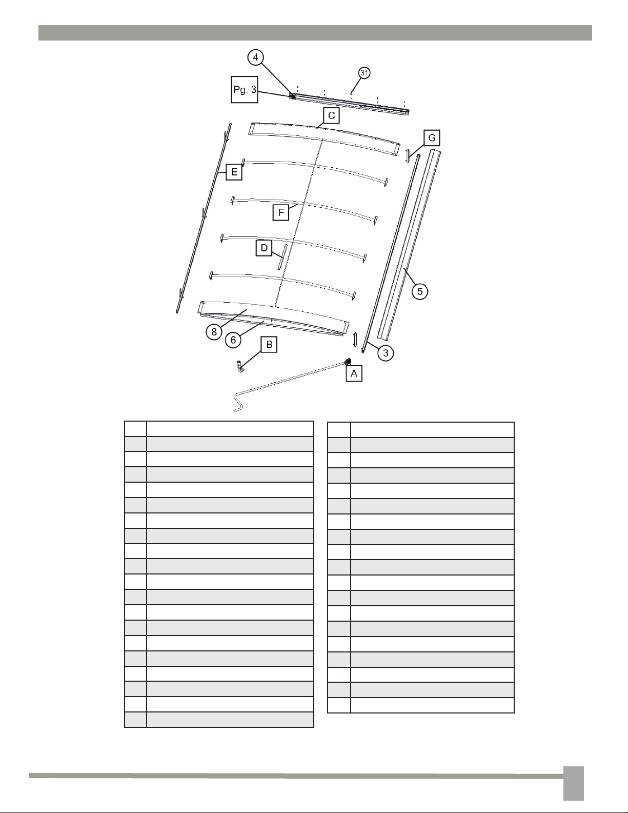
ROLL TARP ASSEMBLY
Front
# Description
1 Tarp Crank Handle Small
2 1” x 1” 14 GA Square Tubing
3 1.25” x 1.25” Roll Tube
4 Spring Return
5 Lip Lock
6 Back End Plate
7 Front End Plate
8 Back Endcap Arch
9 Front Endcap Arch
10 Nylon Strip
11 Tarp Bows
12 3/16” Diameter Ridge Cable
13 Stop Bracket
14 Prop Up Bar
15 Plastic Standoffs
16 J-Bolt
17 Canvas Tarp
18 Hanger Bracket
19 Hanger Bracket Hook
Back
# Description
20 1/4” Flange Nuts
21 1/4” x 1/2”
22 1/4”x 5/8”
23 1/4” Locknut
24 1/4” x 2 1/2”
25 1/4” x 3/4”
26 3/8” Flange Nuts
27 3/8” x 1” Flange
28 3/8” x 2”
29 3/8” locknut
30 1/4” x 1 1/2” Self Tapping
31 *1/4” x 3/4” Self Tapping
32 1/2” Locknut
33 1/2” x 1 1/4”
34 Small Cable Clamp
35 Large Cable Clamp
36 Universal Joint
37 1/4” Drive Rivet
*Only used on 440/540 & 680/760 Models
1
Page 3
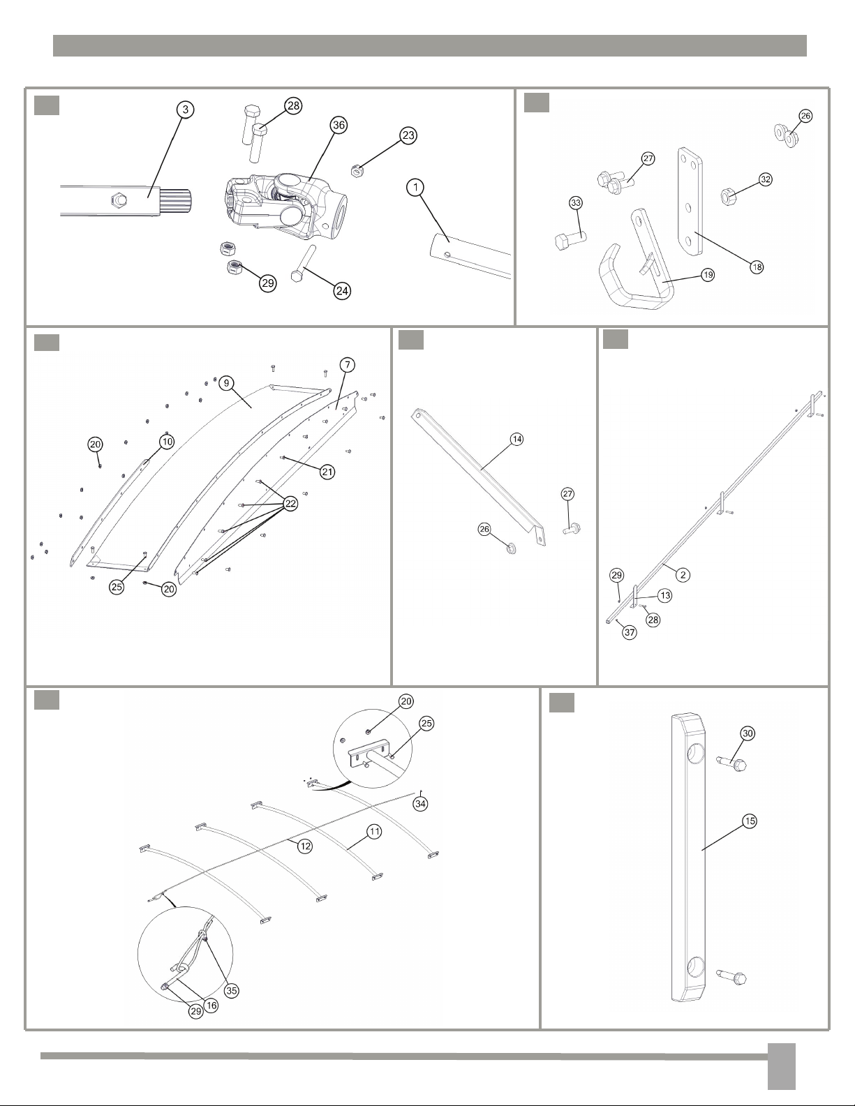
ROLL TARP ASSEMBLY
A
C
D
B
E
F
G
2
Page 4
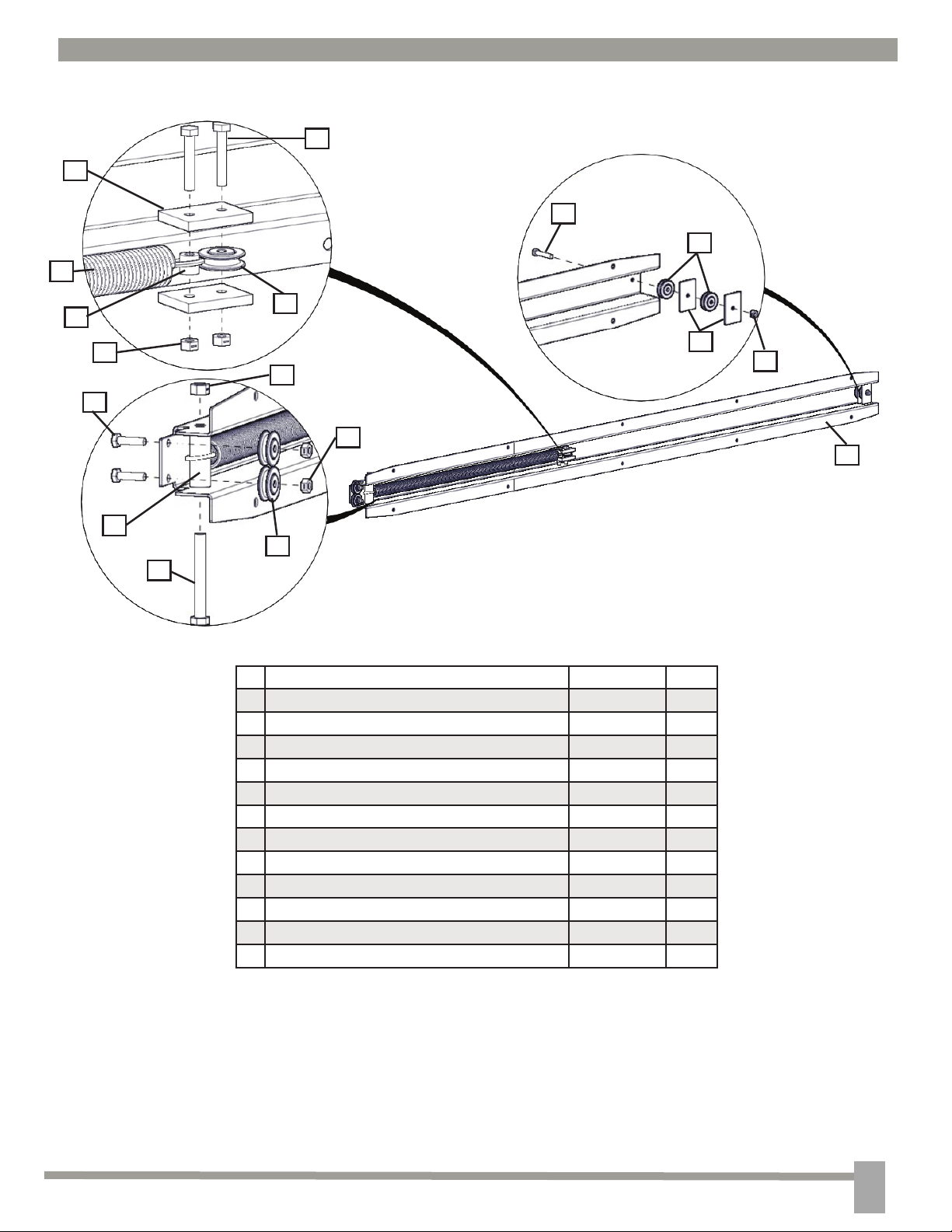
SPRING RETURN ASSEMBLY
2
6
2
3
8
7
5
1
10
9
3
4
5
11
5
12
3
# Description Part # Qty.
1 1/4-20 X 1.0 Grade 5 Zinc Hex Bolt JM0002095 2
2 1/4-20 X 1 1/2 Grade 5 Zinc Hex Bolt JM0002447 1
3 Roller Small JM0000200 5
4 Aluminum Spacer Square JM0000202 2
5 1/4-20 Grade 5 Zinc Centerlock Nut JM0001505 5
6 Rectangular Plastic Spacer JM0000205 2
7 Short Plastic Spacer JM0000206 1
8 Spring Return Spring JM0000207 1
9 3/8-16 X 3.0 Grade 5 Zinc Hex Bolt JM0001666 1
10 Tall Plastic Spacer JM0000209 1
11 3/8-16 Grade 5 Zinc Centerlock Nut JM0001512 1
12 Spring Return Housing JM0002446 1
3
Page 5
OCS (Opposite Chute Side)
STANCE
Back
Front
CS (Chute Side)
4
Page 6

STEP 1 - HANGER
1.1 Mark two holes using the Hanger Bracket as a template and drill with a 3/8” drill bit. These holes
should be centered on the back vertical face of the gravity box as low as possible.
1.2 Fasten the Hanger Bracket to the gravity box using two 3/8” x 1” serrated ange bolts and two 3/8” serrated ange nuts.
1.3 Fasten the Hanger Hook to the Hanger Bracket as shown above with a 1/2” x 1 1/4” bolt and a 1/2”
locknut. This should not be tightened all the way. The Hanger Hook needs to be able to swivel on the
Hanger Bracket.
5
Page 7

STEP 2 - ENDCAPS ASSEMBLY
2.1 Aside from the gravity box, match up the holes on the Front Endcap Arch with the top Front Endcap
Plate holes.
2.2 Install the Nylon Strip Opposite Chute Side (OCS) using 1/4” x 5/8” bolts and 1/4” serrated ange nuts.
2.3 Insert 1/4” x 1/2” bolts in the remaining holes. Fasten with 1/4” serrated ange nuts.
2.4 Repeat Steps 2.1 - 2.3 for the back endcap arch and plate.
-NOTE: Since there is no wind lip on the back endcap, it doesnt include a Nylon Strip so only 1/4”
x 1/2” bolts should be used.
6
Page 8

STEP 3 - PLACE LIP LOCK AND ENDCAPS
3.1 Rest the lip lock OCS and centered on the top of the Gravity Box.
3.2 Rest the assembled front and back Endcaps in place.
STEP 4 - ENDCAPS
440/540 & 680/760 Models
4.1 Using the lower holes on the front Endcap Plate
as a guide, drill holes through the front using a 1/4”
drill bit.
4.2 Insert 1/4” x 1/2” bolts and fasten using 1/4” ser-
rated fange nuts.
4.3 Repeat steps 4.1 & 4.2 for the back Endcap.
250 & 385 Models
4.1 Install the Spring Return onto the front Endcap
using only the bottom ve holes. Fasten using 1/4” x
1/2” bolts and 1/4” serrated ange nuts.
4.2 Drill holes with a 1/4” drill bit through the outer
lip of the sideboard using the top ve holes of the
Endplate/Spring Return as a guide.
4.3 Insert 1/4” x 3/4” bolts and fasten using 1/4” serrated fange nuts.
4.4 Repeat Steps 4.2 & 4.3 for the back endcap.
-NOTE: No spring return is installed on the
back so only 1/4” x 1/2” bolts should be used.
7
Page 9

STEP 5 - ENDCAPS CONTINUED
5.1 Use the four holes on the top of the front Endcap
as a guide to drill four holes from the top using a 1/4”
drill bit.
5.2 Insert 1/4” x 3/4” bolts and fasten with 1/4” ser-
rated ange nuts.
5.3 Repeat Steps 5.1 & 5.2 for the back Endcap.
STEP 6 - SPRING RETURN
NOTE: This step is only pertains to 440/540 & 680/760 Models
Install the Spring Return on the front of the gravity
box using ten 1/4” x 3/4” self tapping bolts. Be sure
the end with the cable loop is OCS. It should be
positioned up against the OCS corner brace. See the
chart below for model specic Spring Returm locations.
Model Spring Return Location
440 Above ladder - straddling Ripple
680 Below ladder - straddling Ripple
540 & 760 Above ladder - straddling Shell/
STEP 7 - KNEE BRACES
7.1 Mark the hole for the Knee Brace as centered
as possible using the Knee Brace as a guide. When
marking the hole push up on the Endcap to keep it
from sagging.
7.2 Drill the hole using a 3/8” bit.
7.3 Use a 3/8” x 1” serrated ange bolt and a 3/8”
serrated ange nut to fasten the knee brace. Be sure
that the knee breace applies upward pressure to the
Endcap.
7.4 Repeat Steps 7.1-7.3 for the remaining knee
brace under the opposite Endcap.
Sideboard Seam (as shown on left)
8
Page 10

STEP 8 - TARP BOWS
9.1 Position the Tarp Bows on top the Gravity
Box. Be sure to spread the Bows out evenly
from front to back.
9.2 Using the Tarp Bows as a guide, drill holes
with a 1/4 ” drill bit.
-NOTE: There may be existing holes
in the Lip Lock for the bows. If these
holes are not in the correct location, new
holes will have to be drilled through the
lip lock.
9.3 Insert 1/4” x 3/4” bolts and fasten with 1/4”
serrated ange nuts.
STEP 9 - CABLE
8.1 Tighten the Small Cable Clamp close to one end of the 3/16” diameter cable.
8.2 Pull the opposite end through the center hole of the front Endcap, over all of the Tarp Bows, then through
the center hole on the back Endcap.
8.3 With the remaining cable pulled through the back endcap, make the cable into a loop using the large
cable clamp but do not tighten.
8.4 Insert the J-Bolt into the the remaining center hole on the back Endplate and hand tighten it with a 3/8”
locknut.
8.5 Hook the cable loop around the J-Bolt and pull the cable taught over the Bows before tightening the
Large Cable Clamp .
8.6 Tighten the locknut until the cable is well taught over the bows.
-NOTE: Use a vise grips on the J-Bolt while tightening to keep it from spinning.
9
Page 11

STEP 10 - PLASTIC STANDOFFS
Using 1/4” x 1 1/2” self tapping screws mount
the Plastic Standoffs 2” below the drip edge and
right up against the corner brace as shown on
the left.
STEP 11 - 1” SQUARE TUBE
2”
11.1 Insert the 1” 14 ga Square Tube into the tarp sleeve on the opposite side of the stiffening patch (see pg. 11,
Step 13 for a picture of the stiffening patch).
11.2 Center the 1” Square Tube inside the sleeve. This should leave around 2” of the tube sticking out of the
sleeve on each side as shown above.
11.3 Use a 1/4” drill bit to drill a hole through the Canvas Tarp and one wall of the 1” Square Tube. The hole
should be around 3/4” from the edge of the tarp.
11.4 Use a hammer to install a 1/4” Drive Rivet.
11.5 Repeat Steps 11.3 & 11.4 at the same location on the other end of the Square Tube.
-NOTE: Be sure the Tarp is pulled tight over the Square Tube in between the Rivets.
3/4”
10
Page 12

STEP 12 - STOP BRACKETS
14”
CS
12.1 Center the 1” Square Tube that is riveted to the Canvas Tarp on the CS of the gravity box. Allow the Square
Tube to hang below the top bolts on the corner brackets (around 2 1/2” below top of the Gravity Box).
12.2 Drill two holes around 14” from the end of the Tube through the Tubing and sideboard wall. A third hole
should be drilled as centered on the tube as possible. Avoid drilling through the center brace inside the gravity box.
12.3 Install each stop bracket with a 3/8” x 2” bolt and a 3/8” locknut.
STEP 13 - 1 1/4” SQUARE TUBE
Stiffening
Patch
1 1/4”
OCS
13.1 On the opposite side of the Canvas Tarp, slide the 1 1/4” Square Tube into the remaining sleeve until the spool
lines up with the pulleys on the Spring Return. The splined end of the 1 1/4” Square Tube should be towards the
back of the Gravity Box.
13.2 With a 1/4” drill bit, drill a hole through each of the stiffening patches and one wall of the 1 1/4” Square Tube.
Also drill a hole at each end of the 1 1/4” Square Tube around 1 1/4” from the edge of the Canvas Tarp.
13.3 Use a hammer to install 1/4” drive rivets into each of the drilled holes.
13.4 Slip the Spring Return cable loop over the spool.
11
Page 13

STEP 14 - U-JOINT & CRANK HANDLE
14.1 Install the Universal Joint using two 3/8” x 2” bolts and two 3/8” locknuts.
14.2 Install the Crank Handle using one 1/4” x 2 1/2” bolt and one 1/4” locknut.
-NOTE: Universal Joint may be pre-assembled to the Crank Handle.
12
Page 14

ROLL TARP PART NUMBERS
Common Roll Tarp Parts
Description Part No. Qty.
Nylon Strip JM0001471 1
Stop Bracket JM0001494 3
Prop Up Bar JM0000917 2
Plastic Standoffs JM0001496 2
J-Bolt-Small JM0001519 1
Hanger Bracket JM0000815 1
Hanger Bracket Hook JM0001497 1
1/4” Flange Nuts JM0001499 52*
1/4” x 1/2” JM0001481 27
1/4”x 5/8” JM0001479 5
1/4” Locknut JM0001505 1
1/4” x 2 1/2” JM0001506 1
1/4” x 3/4” JM0001507 20*
3/8” Flange Nuts JM0001508 4
3/8” x 1” Flange JM0001509 4
3/8” x 2” JM0001510 5
3/8” Locknut JM0001512 6
1/2” Locknut JM0001511 1
1/2” x 1 1/4” JM0001513 1
1/8” Cable Clamp JM0001514 1
3/16” Cable Clamp JM0001515 1
Universal Joint JM0001517 1
1/4” Drive Rivet JM0001518 10
1/4” x 1 1/2” Self Tapping JM0001571 4
*Add 4 to quanity for every tarp bow
added after 3 total.
Model Specic Roll Tarp Parts
Description Part No. Qty.
250 Roll Tarp
Tarp Crank Handle Small JM0000889 1
1” x 1” 14 ga Square Tubing x 120” JM0001531 1
1.25” x 1.25” Roll Tube 126” JM0001537 1
Drip Edge 120” JM0001549 1
Back Endcap Arch 84” JM0001546 1
Front Endcap Arch 84” JM0001543 1
Back End Plate 84” JM0001549 1
Front End Plate 84” JM0001545 1
250 Tarp Bows JM0001583 3
3/16” Diameter Ridge Cable 120” JM0001525 1
250 Canvas Tarp JM0001589 1
385 Roll Tarp
Tarp Crank Handle Small JM0000889 1
1” x 1” 14 ga Square Tubing x 148” JM0001534 1
1.25” x 1.25” Roll Tube 154” JM0001538 1
Drip Edge 148” JM0001552 1
Back Endcap Arch 94” JM0001554 1
Front Endcap Arch 94” JM0001550 1
Back End Plate 94” JM0001555 1
Front End Plate 94” JM0001551 1
385 Tarp Bows JM0001584 3
3/16” Diameter Ridge Cable 148” JM0001524 1
385 Canvas Tarp JM0001588 1
440/540 Roll Tarp
Tarp Crank Handle Small JM0000889 1
1” x 1” 14 ga Square Tubing x 180” JM0001535 1
1.25” x 1.25” Roll Tube 186” JM0001539 1
Drip Edge 180” JM0001567 1
Back Endcap Arch 100” JM0001565 1
Front Endcap Arch 100” JM0001563 1
Back End Plate 100” JM0001566 1
Front End Plate 100” JM0001564 1
440 Tarp Bows JM0021006 3
540 Tarp Bows JM0000812 3
3/16” Diameter Ridge Cable 180” JM0001526 1
1/4” x 3/4” Self Tapping JM0001570 4
440/540 Canvas Tarp JM0001587 1
680/760 Roll Tarp
Tarp Crank Handle Medium JM0001541 1
1” x 1” 14 ga Square Tubing x 198” JM0001536 1
1.25” x 1.25” Roll Tube 204” JM0001540 1
Drip Edge 198” JM0001576 1
Back Endcap Arch 114” JM0001574 1
Front Endcap Arch 114” JM0001572 1
Back End Plate 114” JM0001575 1
Front End Plate 114” JM0001573 1
680 Tarp Bows JM0021010 4
760 Tarp Bows JM0001585 4
3/16” Diameter Ridge Cable 198” JM0001527 1
1/4” x 3/4” Self Tapping JM0001570 4
680/760 Canvas Tarp JM0001586 1
13
 Loading...