

Page 1

MANUAL HEADER
O P E R A T O R’ S M A N U A L
SPEED TENDER PRO 450
Revision 2/26/2013
J. & M. MFG. Co., Inc.
P.O. Box 547 Ft. Recovery, OH 45846
PH: (419) 375-2376
www.jm-inc.com
Page 2

TABLE OF CONTENTS
General Information
To e Dealer 4
Express Warranty 4
Service 5
To e Owner 6
Safety Rules 6-7
1.0 Operations
1.1 Preparing the Towing Vehicle 8
1.2 Preparing Speed Pro 8
1.3 Connecting Speed Pro to the Towing Vehicle 8
1.4 Transporting 9
1.5 Hydraulic Power Unit Operation 9-10
1.6 Field Operation 11
1.7 Basic Scale Operations 12
1.8 Auger Cleanout 12
2.0 Service
2.1 Tire Pressure 12
2.2 Tightening Lugnuts 12
2.3 Wheel Bearings 13
2.4 Hydraulic Power Unit 14
2.5 Electric Brakes 14-18
2.6 Daily Service 18
2.7 End of the Year Service 18-19
2.8 Removing From Storage 19
2.9 Troubleshooting 20-22
2.10 Bolt Torque Specications 23
3.0 Hydraulics 24
4.0 Wiring 25
5.0 Parts
5.1 Chassis 26-27
5.2 Frame Weldment 28-29
5.3 Auger Assembly 30-31
Page 3
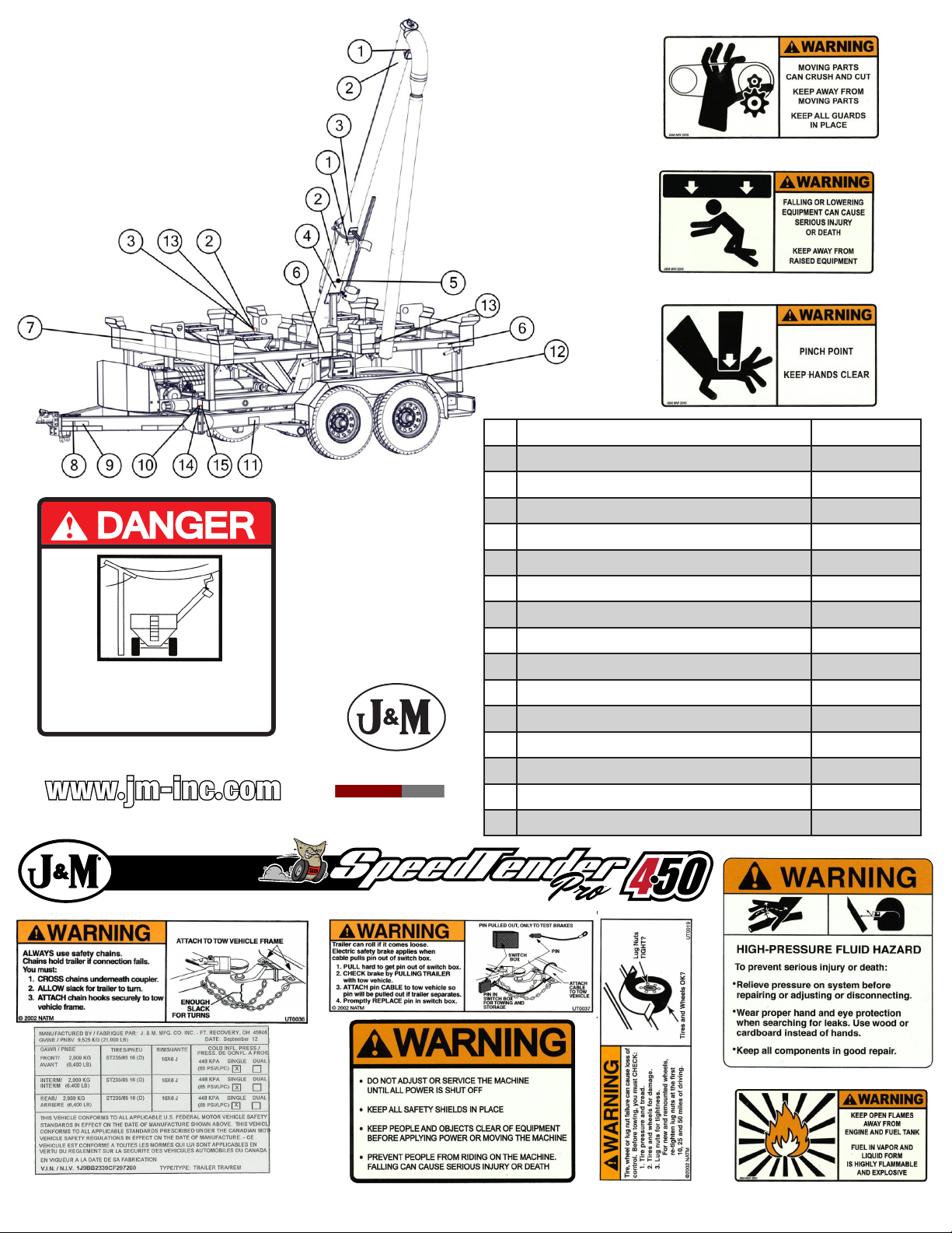
If a decal is torn or faded, it
needs to be replaced.
# Description Part. No.
1 Warning/Moving Parts JM0014993
2 Warning/Falling or Lowering JM0014992
3 Warning/Pinch Point JM0014994
4 Danger/Serious Injury Elec Lines JM0015099
5 Small J&M Oval JM0010179
6 Red & White Reective Tape JM0015079
7 Speed Pro 450 JM0025336
8 Warning/Safety Chains JM0014995
9 Warning/Trailer Can Roll JM0014997
10 Warning/High Pressure JM0010163
11 Chassis Manufacture # N/A
12 www.jm-inc.com JM0019239
13 Warning/Tire Wheel Lugnuts JM0014996
14 Warning/Do Not Adjust JM0014979
15 Warning/Open Flames JM0014983
Page 4

GENERAL INFORMATION
TO THE DEALER:
Read manual instructions and safety rules. Make sure all items on the Dealer’s Pre-Delivery and Delivery
Check Lists in the Operator’s Manual are completed before releasing equipment to the owner.
The dealer must complete the Warranty Registration found on the Dealer Portal website located at
dealer.jm-inc.com. and return it to J. & M. Mfg. Co., Inc. at the address indicated on the form. Warranty claims
will be denied if the Warranty Registration has not been submitted.
EXPRESS WARRANTY:
J. & M. Mfg. Co. Inc. warrants against defects in construction or materials for a period of ONE year. We reserve the right to inspect and decide whether material or construction was faulty or whether abuse or accident
voids our guarantee.
Warranty service must be performed by a dealer or service center authorized by J. & M. Mfg. Co. Inc. to sell
and/or service the type of product involved, which will use only new or remanufactured parts or components
furnished by J. & M. Mfg. Co. Inc. Warranty service will be performed without charge to the purchaser for
parts or labor based on the Warranty Labor Times schedule. Under no circumstance will allowable labor times
extend beyond the maximum hours indicated in the Warranty Labor Times schedule for each warranty procedure. The purchaser will be responsible, however, for any service call and/or transportation of the product to
and from the dealer or service center’s place of business, for any premium charged for overtime labor requested
by the purchaser, and for any service and/or maintenance not directly related to any defect covered under the
warranty. Costs associated with equipment rental, product down time, or product disposal are not warrantable
and will not be accepted under any circumstance.
Each warranty term begins on the date of product delivery to the purchaser. Under no circumstance will warranty be approved unless (i) the product warranty registration card (attached to the inside of the Operator’s
Manual) has been properly completed and submitted to the equipment manufacturer, and (ii) a warranty authorization number has been issued by the equipment manufacturer. This Warranty is effective only if the warranty registration card is returned within 30 days of purchase.
This warranty does not cover a component which fails, malfunctions or is damaged as a result of (i) improper
modication or repair, (ii) accident, abuse or improper use, (iii) improper or insufcient maintenance, or (iv)
normal wear or tear. This warranty does not cover products that are previously owned and extends solely to the
original purchaser of the product. Should the original purchaser sell or otherwise transfer this product to a third
party, this Warranty does not transfer to the third party purchaser in any way. J. & M. Mfg. Co. Inc. makes no
warranty, express or implied, with respect to tires or other parts or accessories not manufactured by J. & M.
Mfg. Co. Inc. Warranties for these items, if any, are provided separately by their respective manufacturers.
THIS WARRANTY IS EXPRESSLY IN LIEU OF ALL OTHER WARRANTIES OR CONDITIONS,
EXPRESS, IMPLIED OR STATUTORY, INCLUDING ANY IMPLIED WARRANTY OF MERCHANTABILITY OR FITNESS FOR PARTICULAR PURPOSE.
In no event shall J. & M. Mfg. Co. Inc. be liable for special, direct, incidental or consequential damages of any
kind. The exclusive remedy under this Warranty shall be repair or replacement of the defective component at J.
& M. Mfg. Co. Inc.’s option. This is the entire agreement between J. & M. Mfg. Co. Inc. and the Owner about
warranty and no J. & M. Mfg. Co. Inc. employee or dealer is authorized to make any additional warranty on
behalf of J. & M. Mfg. Co. Inc.
4
Page 5

GENERAL INFORMATION
The manufacturer reserves the right to make product design and material changes at any time without notice.
They shall not incur any obligation or liability to incorporate such changes and improvements in products previously sold to any customer, nor shall they be obligated or liable for the replacement of previously sold products
with products or parts incorporating such changes.
SERVICE:
The equipment you have purchased has been carefully manufactured to provide dependable and satisfactory use.
Like all mechanical products, it will require cleaning and upkeep. Lubricate the unit as specied. Observe all
safety information in this manual and safety signs on the equipment.
For service, your authorized J. & M. dealer has trained mechanics, genuine J. & M. service parts, and the necessary tools and equipment to handle all your needs.
Use only genuine J. & M. service parts. Substitute parts may void the warranty and may not meet standard required for safe and satisfactory operating. Record the model number and serial number of your equipment in the
spaces provided:
Serial #_______________ Purchase Date: _______________ Purchased From: ____________________
Please provide this information to your dealer to obtain the correct parts.
5
Page 6

GENERAL INFORMATION
TO THE OWNER:
The purpose of this manual is to assist you in operating and maintaining your Speed Pro in a safe manner. Read
it carefully. It furnishes information and instructions that will help you achieve years of dependable performance
and help maintain safe operating conditions. If this machine is used by an employee or is loaned or rented, make
certain that the operator(s), prior to operating:
1. Is instructed in safe and proper use.
2. Review and understands the manual(s) pertaining to this machine.
Throughout this manual, the term IMPORTANT is used to indicate that failure to observe can cause damage to
equipment. The terms CAUTION, WARNING and DANGER are used in conjunction with the Safety-Alert Sym-
bol. When you see this symbol, carefully read the message that follows and be alert to the possibility of personal
injury or death.
This Safety-Alert symbol indicates a hazard and means
ATTENTION! BECOME ALERT! YOUR SAFETY IS INVOLVED!
DANGER:
WARNING:
CAUTION:
IMPORTANT:
NOTE:
Indicates an imminently hazardous situation that, if not avoided, will result in death or
serious injury.
Indicates a potentially hazardous situation that, if not avoided, could result in death or serious injury, and includes hazards that are exposed when guards are removed.
Indicates a potentially hazardous situation that, if not avoided, may result in minor or moderate injury.
Indicates that failure to observe can cause damage to equipment.
Indicates helpful information.
SAFETY RULES:
ATTENTION! BECOME ALERT! YOUR SAFETY IS INVOLVED!
Safety is a primary concern in the design and manufacture of our products. Unfortunately, our efforts to provide safe equipment can be erased by an operator’s single careless act. In addition, hazard control and accident
prevention are dependent upon the awareness, concern, judgment, and proper training of personnel involved in
the operation, transport, maintenance and storage of equipment.
Make certain that the operator(s), prior to operating is instructed in safe and proper use and reviews and understands the manual(s) pertaining to this machine. Also make certain that the operator(s) reviews and understands
the operator’s manual of the tow vehicle prior to hooking up or operating the Speed Pro.
Read this manual before you operate this machine. If you do not understand any part of this manual, or need
more information, contact the manufacturer or your authorized dealer.
Safety Rules Next Page
6
Page 7

GENERAL INFORMATION
1. Understand that your safety and the safety of other persons are measured by how you service and operate
this ma chine. Know the positions and functions of all controls before you try to operate them. Make sure
to check all controls in a safe area before starting your work.
2. The safety information given in this manual does not replace safety codes, federal, state, or local laws.
Make certain your machine has the proper equipment as designated by local laws and regulations.
3. A frequent cause of personal injury or death is from persons falling off equipment and being run over. Do
not permit persons to ride on this machine.
4. Secure Speed Pro safety chain to towing vehicle before transporting. Do not transport without safety
chains being attached to tow vehicle.
6. Use good judgment when transporting Speed Pro on a highway. Maintain complete control at all times.
Regulate speed to road conditions. Do not transport unit with rear compartment full and front compartment
empty. The unit may not be properly balanced, offsetting the tongue weight of the Speed Pro.
7. When transporting on public roads, the conveyor must be in the forward position to meet with lighting and
visibility marking requirements.
8. Do not travel faster than 10 mph. during off highway travel. Drive slowly over rough ground, hill sides,
and around curves to avoid tipping. Use extreme care when operating close to ditches, fences, or on hill
sides.
9. Use care when moving or operating Speed Pro near electric lines as serious injury or death can result
from contact.
10. Never adjust, service, clean, or lubricate Speed Pro until all power is shut off and the battery is
disconnected. Keep all safety shields in place.
11. Carbon monoxide can cause severe nausea, fainting, or death. Do not operate engine in closed or conned
work area.
12. Explosive fuel can cause res and severe burns. Stop engine before lling fuel tank.
13. Hot parts can cause severe burns. Do not touch engine while operating or just after stopping.
14. Hydraulic oil leaking under pressure can penetrate skin and cause infection or other injury.
15. To prevent personal injury when working with hydraulic power unit:
a. Relieve all pressure before disconnecting uid lines.
b. Before applying pressure, make sure all connections are tight and components are in good
condition.
c. Never use your hand to check for suspected leaks under pressure. Use a piece of cardboard or wood
for this purpose.
16. Make sure that everyone is clear of equipment before applying power or moving the Speed Pro.
18. Before unhooking the Speed Pro from the transport vehicle, be sure to properly block the wheels to
prevent the Speed Pro from moving.
7
Page 8

OPERATIONS
1.1 Preparing the Towing Vehicle
Before towing the Speed Pro, refer to towing vehicle’s owner’s manual for information concerning hitch
capacities, hitch adjustments, and tire ination.
Towing vehicle must be equipped with proper electric braking components.
NOTE: The Speed Pro is equipped with LED lights. The towing vehicle may require a
asher upgrade for lights to operate properly.
Do not exceed towing vehicles GVWR (Gross Vehicle Weight Rating) or GCWR (Gross Combination Weight
Rating), or the maximum hitch load.
1.2 Preparing Speed Pro
Hydraulics: Check routing of all hydraulic hoses. Hoses should not be kinked, twisted or rubbing against sharp
edges. Check all hoses and ttings for hydraulic leaks. Tighten and /or repair or replace as required.
Lubrication: Lubricate Speed Tender as outlined in Service section 2.1. Refer to engine manual for proper uid
levels in engine.
Tires/Wheels: Check tire pressures and maintain at recommended operating pressure. It is important to check
wheel nut/bolts for proper torque as recommended. You can nd proper tire pressure and wheel torque located in
service manual section.
1.3 Connecting Speed Pro to the Towing Vehicle
WARNING: Do not stand between the Speed Pro and tow vehicle when hooking up.
NOTE: The Speed Pro comes standard with a 2 5/16” ball coupler and has an optional
3” lunette eye. Also the Speed Pro can come with an optional Gooseneck Frame in place
of the A-Frame. The Gooseneck Frame can feature either a 2 5/16” ball coupler or a 5th
Wheel hook up.
1. Back tow vehicle up to Speed Pro.
2. Align the vehicle’s ball or lunette eye with the coupler or ring on the Speed Pro.
3. Lift tongue latch lever.
4. Lower jack to set Speed Pro coupler down on ball or lunette eye hook.
5. Latch coupler and insert pin. Check to make sure that coupler is securely latched.
6. Pivot jack to transport position and pin in place.
7. Attach 7-way plug to tow vehicle. Check the length of the Speed Pro 7-way to make sure that
it is long enough to turn, but not too long to touch the ground.
NOTE: Check to make sure that lights are in proper operating condition and repair or
replace if necessary.
8. Connect the brake breakaway cable to towing vehicle.
9. Attach safety chains to tow vehicle by crossing chains (Figure 1.1). Allow enough slack in
chains necessary for turning.
10. Test the brakes and all the lights on the Speed Pro
WARNING: Check safety chains for broken, stretched or damaged link or end ttings.
Replace chains if found to be damaged. Do not weld safety chains.
8
Page 9
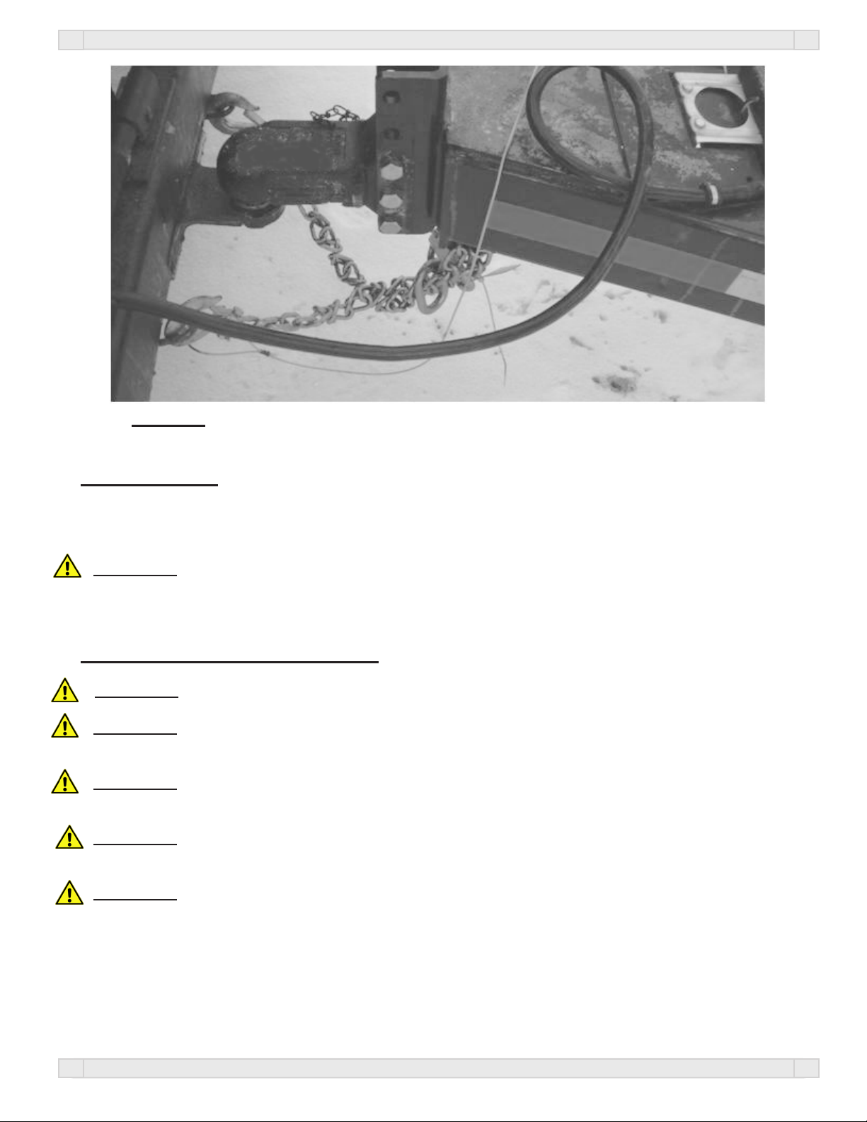
Figure 1.1
OPERATIONS
1.4 Transporting
NOTE: Make sure the jack is in the horizontal position before transporting.
When transporting the Speed Pro on public roads, it is recommended to have the auger in the storage position.
WARNING: Travel at a safe speed that allows you to maintain complete control of towing vehicle and
Speed Pro at all times.
1.5 Hydraulic Power Unit Operation
WARNING: Explosive fuel can cause res and severe burns. Stop engine before lling fuel tank.
WARNING: Carbon monoxide can cause severe nausea, fainting or death. Do not operate
engine in an enclosed or conned area.
WARNING: Hot parts can cause severe burns. Do not touch engine while operating or just after
stopping.
WARNING: Acid from battery can cause res and severe acid burns. Make sure to charge
battery in well-ventilated area.
WARNING: Make sure to relieve hydraulic pressure before working on hydraulic system.
9
Page 10
OPERATIONS
WARNING: Purge hydraulic system of air before operating Speed Pro to prevent serious injury or
death.
WARNING: Wear proper hand and eye protection when searching for leaks. Use wood or cardboard
instead of hands.
1. Check to make sure all ttings and hardware are in proper operating condition. Replace if worn or
broken. Check engine uid levels and sight gauge on reservoir for proper operating levels.
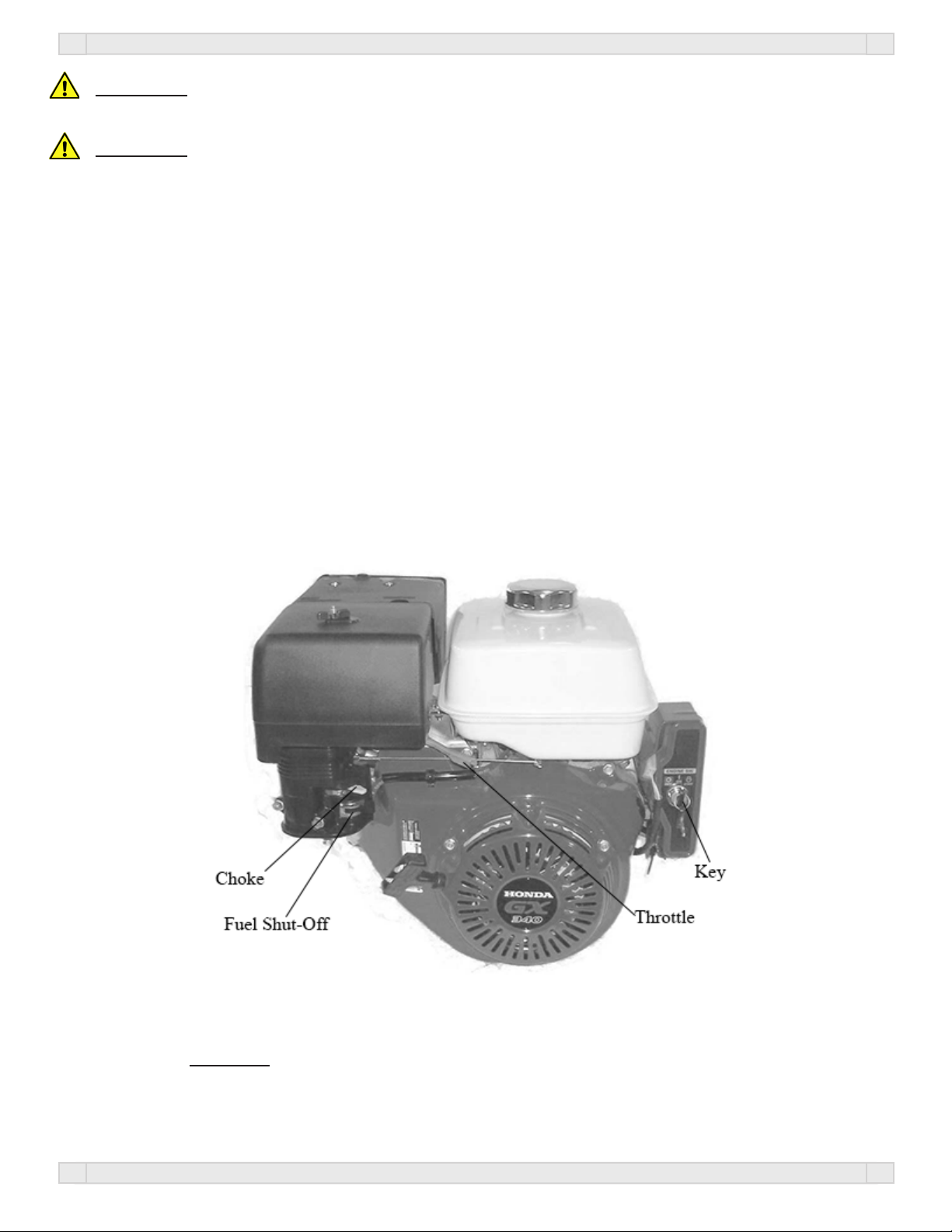
2. Slide the Fuel Shut-off Lever to the “ON” position (Figure 1.2).
3. Slide Choke Lever to the “ON” position (Figure 1.2).
4. Turn the key to the start position. Once engine starts, release key (Figure 1.2).
5. After starting, allow the engine to warm-up. Slide choke to the “OFF” position, and increase throttle
speed (Figure 1.2).
6. To turn the engine off, slide the Fuel Shut-off to the “OFF” position (Figure 1.2).
NOTE: In extremely cold weather, it is best to allow engine and hydraulics to warm-up before
increasing throttle speed.
NOTE: If a hydraulic leak appears, turn off immediately and take appropriate action.
NOTE: See Engine manual for more details on upkeep and service.
Figure 1.2
10
Page 11

OPERATIONS
1.6 Field Operation
WARNING: The Speed Pro must be hooked to the towing vehicle during loading and
unloading.
1. Position the Speed Pro next to the planter/drill so the auger will reach the planter box.
2. Start the hydraulic power unit and increase throttle speed. (Allow hydraulic uid to warm-up.)
(Figure 1.2).
3. Extend the auger to unload position using the handheld controller/wireless remote.
Conveyer/Auger
Up
E
F
JM0014984
Starts/Stops Motor
Raises/Lowers Conveyer
Start
Conveyer/Auger
J
N
M
E Blue
F Yellow
J Red
M Green/Black
N Green
WARNING: Empty-out the rear compartment rst to help prevent the chance of ipping the
Speed Pro.
9. Use the Handheld Control or Wireless Remote to start the auger.
10. Fill the planter/drill to desired level then repeat.
NOTE: Adjusting engine throttle will regulate auger speed.
11. Run the engine at 1/2 to full rpm for 20 minutes to recharge the battery.
12. Slide the fuel shut off lever to the “OFF” position. This will allow the engine to shutoff by running out
of gas.
13. Turn the key to the “OFF” position.
Reprogramming the Key Fob and Receiver:
To complete the learn procedure, simply do the following. Power up the unit. When you do so, the LED on the
receiver unit will ash “RED” four times. This indicates that the unit has received power. There is magnetically controlled
switching circuitry embedded in the receiver unit. Place a fairly powerful magnet on the back of the receiver for a brief
moment (3 seconds), and the remove it. The LED will go to a constant RED stare. Now immediately press any button on the
transmitter you are attempting to learn in. The LED will go to a GREEN/YELLOW color. This conrms that the receiver
has picked up a signal from the transmitter, and subsequently learned that signal. Communication has been established, and
it is now ready to function properly.
Troubleshooting:
Should the above procedure not complete successfully, wait until the LED light goes out, and repeat the procedure. If for
any reason you experience a second failure of the learn procedure, do the following. Place the magnet on the learn area
and the LED will go to a constant RED stare. Leave the magnet in place on the receiver until the LED light goes out.
(Approximately 10 seconds). This action completely clears the receiver’s memory. Once you have cleared the memory,
proceed with the standard learn procedure detailed above for the key fob transmitters.
11
Page 12

OPERATIONS
1.7 Basic Scale Operations
1. Turn the scale “ON” by pressing the on/off button. The display shows “Hello” then the current weight
value is displayed.
2. Press G/N to access the gross mode. (Live scale weight is displayed in the G/N weighing mode.)
3. In the gross mode, press the ZERO/CLEAR key to zero the indicator when the Speed Tender is empty.
4. After initial amount is placed on the scale, press the TARE Key. (Weight is tarred off and goes into net
mode, showing weight).
5. Load or unload material as needed (Shows + when loading and a – value when unloading).
6. When the display reaches the proper amount, stop loading or unloading.
7. Repeat steps 2 through 4 until complete.
NOTE: For more information, refer to the scale manual.
1.8 Auger Cleanout
1. Raise the clean out door on the auger.
2. Run the auger in reverse until all of the grain is removed.
3. Close the clean out door.
2.0 Service
1. Grease the auger bearing every 10 hours of operation and before storage. Use only two pumps of grease.
2.1 Tire Pressure
The following is to be used as a general guide
for tire ination. Figures can vary depending on
specic brand of tire used. It is important that tires
are inspected before and after unit is loaded. Start
with the minimum pressure indicated. The tire
should stand up with no side wall buckling or distress as tire rolls. Do not exceed maximum recom-
mended tire pressure. 80 psi is the cold rating on
the tire that is standard for the Speed Pro.. J&M
also recommends to rotate your tires front to back
(not side to side) every 1,200 miles or 12 months
(whichever comes rst) for longer tire life. Figure
2.3 is a troubleshooting chart used to ensure the
tires wear evenly.
Fig. 2.3
2.2 Tightening Lugnuts
Torque lug-nuts on new and removed wheels to 220 ft. lbs. after the rst 10, 25, and 50 miles of driving, then
recheck torque every 50 hours or every year, whichever comes rst.
12
Page 13

SERVICE
2.3 Wheel Bearings
The wheel bearings need to be cleaned, inspected, and repacked every 12 months or 12,000 miles. Use a number
2 wheel bearing grease to repack the bearings.
Bearing Inspection and Service:
1. Jack up Speed Pro.
2. Remove wheel lug-nuts.
3. Remove wheel from hub.
4. Remove grease cap.
NOTE: Be careful not to dent or cut a hole in grease cap.
5. Remove the cotter pin, nut, and washer.
6. Wiggle the hub to take the outer wheel bearing out.
7. Pull hub assembly straight off the axle. If you want to reuse the grease seal, (which is not recommended),
be careful to support the weight of the hub so that the end of the axle does not ruin the rubber part of the
grease seal.
8. To remove the inner bearing, you must remove the grease seal.
9. Remove inner bearing.
10. Wash all grease and oil from the bearing cone using a suitable solvent. Dry the bearing with a clean, lint-
free cloth and inspect each roller completely. If any pitting, scalding, or corrosion is present, then
the bearing must be replaced. The bearing cups inside the hub must be inspected.
NOTE: Bearings must always be replaced in sets of a cone and a cup (See bearing cup replacement
on following page.)
11. Repack inner bearing with new grease.
A. Place a moderate amount of grease in the palm of one hand.
B. Hold the inner bearing, large side down, in your other hand
C. Using the edge of the bearing like an ice-cream scoop, work it in until you see fresh grease
come out of the top side of the bearing.
D. Rotate 1/8 of a turn and repeat until the whole bearing is full of fresh grease.
12. Place the inner bearing in the back of the wheel hub and add a liberal dose of grease.
13. Position the new wheel seal in its recess and lightly set it with a hammer.
NOTE: Be careful to not deform the metal part of the seal.
14. Slide the hub assembly onto the spindle and push it back into position.
15. Grease the outer bearings by hand. (See step 11)
16. Slide it and the spindle washer onto the spindle and into the hub recess.
17. Install and bottom out the spindle nut, then back it off 1/4 turn.
18. Reinstall the spindle nut and replace the cotter pin with a new one.
NOTE: If the castle nut does not line up with the hole in the spindle, then loosen the nut
slightly until it does.
19. Pack the bearing cap with fresh grease and lightly drive it into the hub recess with a hammer.
20. Reinstall the wheel onto the hub and torque the wheel lug-nuts.
NOTE: See wheel nut/bolt torque requirements located in section 2.10.
Bearing cup replacement:
1. Place the hub on a at work surface with the cup to be replaced on the bottom side.
2. Using a brass drift punch, carefully tap around the small diameter end of the cup to drive it out.
3. After cleaning the hub bore area, replace the cup by tapping it with the brass drift punch. Be sure the cup
is seated all the way up against the retaining shoulder in the hub.
13
Page 14

SERVICE
2.4 Hydraulic Power Unit
Daily (every 5 hours of use):
1. Check oil level.
2. Inspect for oil leaks and repair as necessary.
3. Check all hoses, ttings, bolts and hardware to make sure that they are secure and properly tightened.
4. Check motor oil level. See Engine operator’s manual for details on oil levels, oil types, and service
intervals.
Once per season (every 20-25 hours of use):
Change hydraulic oil lter element with either a NAPA 155Z or a FRAM P1654A Filter.
Every two to three years (every 75-80 hours of use):
Drain oil reservoir and rell with clean, good quality hydraulic AW 32 oil. (It is not recommended to rell
with tractor hydraulic oil).
Replacing hydraulic parts:
Check parts section for proper part description and part # for replacement.
Purge air from system as follows:
1. Disconnect the rod end clevis of all cylinders in a circuit and block up cylinders so the rod can completely
extend and retract without contacting any other components.
2. Pressurize the system and maintain system at full pressure for at least 5 sec. after cylinder rods stop
moving. Check that all cylinders have fully extended or retracted.
3. Check hydraulic reservoir and rell as needed.
4. Pressurize system again to reverse the motion of step 2. Maintain pressure on system for at least 5 sec.
after cylinder rods stop moving. Check that cylinders have fully extended or retracted.
5. Check for hydraulic leaks using cardboard or wood. Tighten connections according to the
torque chart. (pg.23)
6. Repeat steps 2, 3, 4 and 5 (3 to 4 times).
7. Depressurize hydraulic system and connect cylinder rod clevises to their mating lugs.
2.5 Electric Brakes
The Speed Pro is equipped with electric brakes. They need to be inspected and serviced immediately if a loss of
performance is experienced. You need to service your Speed Pro brakes at least once a year with normal use.
How to use your electric brakes properly:
Your Speed Pro brakes are designed to work in synchronization with your tow vehicle brakes. Never use your
tow vehicle or Speed Pro brakes alone to stop the combined load.
Your Speed Pro and tow vehicle will seldom have the correct amperage ow to the brake magnets to give you
comfortable, safe braking unless you make proper brake system adjustments. Changing trailer load and driving
conditions, as well as uneven alternator and battery output, can mean unstable current ow to your brake magnets. It is therefore imperative that you maintain and adjust your brakes as set forth in this manual, use a properly
modulated brake controller, and perform the synchronization procedure noted below.
In addition to the synchronization adjustment detailed below, electric brake controllers provide a modulation
function that varies the current to the electric brakes with the pressure on the brake pedal or amount of deceleration of the tow vehicle. It is important that your brake controller provide approximately 2 volts to the braking
system when the brake pedal is rst depressed and gradually increases the voltage to 12 volts as brake pedal pressure is increased. If the controller “jumps” immediately to a high voltage output, even during a gradual stop, then
the electric brakes will always be fully energized and will result in harsh brakes and potential wheel lockup.
14
Page 15

To synchronize:
To insure safe brake performance and synchronization, read the brake controller manufacturer’s instruction
completely before preforming the synchronization procedure.
Make several hard stops from 20 mph on a dry paved road that is free of sand and gravel. If the Speed Pro
brakes lock and slide, decrease the gain setting on the controller. If they do not slide, slightly increase the gain
setting, adjust the controller just to the point of impending brake lockup and wheel skid.
How to adjust electric brakes:
1. Park the Speed Pro on rm and level ground.
2. Block the trailer tires on the opposite side securely so that no forward or rearward movement is possible.
3. Jack up the Speed Pro.
4. Secure the trailer on jack stands of adequate capacity front and rear.
5. At the back of the wheel, on the brake backing plate, there is a small rubber plug near the bottom of the
backing plate. Pry out this plug to give access to the star wheel adjuster.
6. Insert the brake adjuster tool and maneuver it so that the tool engages with the teeth in the star wheel.
The star wheel looks like a gear with exposed teeth on the perimeter.
7. Turn the adjuster until the brake locks up (you can no longer rotate the wheel by hand). This centers the
brake shoes on the brake drum so that they are in the correct position.
8. Now back off the star wheel 8 to 10 clicks or as specied by the manufacturer. The wheel should spin
freely with no apparent drag to slow it down. A slight scraping noise is normal as the wheel turns.
9. Repeat this procedure for all the wheels
SERVICE
When to adjust brakes:
1. After the rst 200 miles of operating when the brake shoes and drums have “seated.”
2. At 3,000 mile intervals or once a year, whichever comes rst.
Brake Cleaning and Inspection:
Your Speed Pro brakes must be inspected and serviced at yearly intervals, (or more often as use and performance requires). Magnets and shoes must be changed when they become worn or scored thereby preventing
adequate vehicle braking. Clean the backing plate, magnet arm, magnet, and brake shoes. Make certain that all
the parts removed are replaced in the same brake and drum assembly. Inspect the magnet arm for any loose or
worn parts. Check shoe return springs, hold down springs, and adjuster springs for stretch or deformation and
replace if required.
Brake Shoe and Lining Inspection:
A simple visual inspection of your brake linings will tell if they are usable. Replacement is necessary if the lining is worn (to within 1/16” or less), contaminated with grease or oil, or abnormally scored or gouged. Hairline
heat cracks are normal in bonded linings and should not be cause for concern (Figure 2.6). When replacement
is necessary, it is important to replace both shoes on each brake and both brakes of the same axle. This will help
retain the “balance” of your brakes.
Acceptable
Hairline Cracks
Figure 2.6
15
Page 16

SERVICE
Replacing Brake Linings:
1. Remove the brake shoe retract spring.
2. Remove the shoe hold down assembly by holding the back of the pin with one hand and pushing against
the spring and twisting with a hold down spring tool until the cup is released.
3. Remove both shoes together leaving the adjuster assembly and spring intact.
4. Clean the backing plate and lever arm.
5. Inspect magnet arm for any loose or worn parts.
6. Replace springs that are broken, bent, or weak.
7. Apply a light lm of lubricant to the anchor pin and shoe rest pads & backing plate areas that are in
contact with the lever arm.
8. Attach the adjuster screw and spring to the new brake shoes. The star wheel and adjuster must be
positioned as before.
9. Install the new shoes on the backing plate and reinstall shoe retract spring.
After replacement of brake shoes and linings, the brake must be re-burnished to seat in the new components.
This should be done by applying the brakes 20 to 30 times from an initial speed of 40 mph, slowing the vehicle
to 20 mph. Allow ample time for brakes to cool between applications. This procedure allows the brake shoes
to seat into the drum surface.
Brake Lubrication:
Before reassembling, apply a light lm of lubrication or similar grease, or anti-seize compound on the brake
anchor pin, the actuating arm bushing and pin, and the areas of the backing plate that are in contact with the
brake shoes and magnet lever arm. Apply a light lm of grease on the actuating block mounted on the actuating
arm.
Troubleshooting:
Most electric brake malfunctions that cannot be corrected by either brake adjustments or synchronization adjustments can generally be traced to electrical system failure. Mechanical causes are ordinarily obvious, bent or
broken parts, worn out linings or magnets, seized lever arms or shoes, scored drums, loose parts, etc. Voltmeter
and ammeter are essential tools for proper troubleshooting of electric brakes.
How to Measure Voltage:
System voltage is measured at the magnets. Connect the voltmeter to the two magnet lead wires at any brake.
This may be accomplished by using a pin probe inserted through the insulation of the wires dropping down
from the chassis or by cutting the wires. The engine of the towing vehicle should be running when checking the
voltage (so that a low battery will not affect the readings).
Brake Magnet Inspection:
Your electric brakes are equipped with high quality electromagnets that are designed to provide the proper force
and friction. Your magnets should be inspected and replaced if worn unevenly or abnormally (Figure 2.7). Even
if wear is normal as indicated by your straightedge, the magnets should be replaced if any part of the magnet
coil has become visible through the friction material facing of magnet. It is also recommended that the drum
armature surface be re-faced when replacing magnets. Magnets should also be replaced in pairs - both sides of
an axle.
16
Page 17

SERVICE
Straight Edge
Abnormal Wear
(Replace)
Figure 2.7
Voltage in the system should begin at 0 volts. As the controller bar is slowly actuated, the voltage should gradually increases to about 12 volts. This is referred to as modulation. No modulation means that when the controller begins to apply voltage to brakes it applies an immediate high voltage, which causes the brakes to apply
instantaneous maximum power.
The threshold voltage of a controller is the voltage applied to the brakes when the controller rst turns on. The
lower the threshold voltage, the smoother the brakes will operate. Threshold voltage in excess of 2 volts (quite
often found in heavy duty controllers) can cause grabbing, resulting in harsh braking.
How to Measure Amperage:
System amperage is the amperage being drawn by all brakes on the trailer. The engine of the towing vehicle
should be running when checking amperage.
One place to measure system amperage is at the blue wire of the controller which is the output to the brakes.
The blue wire must be disconnected and the amp meter put in series into the line. System amperage draw should
be as noted in the table below. Make sure your ammeter has sufcient capacity and note polarity to prevent
damaging your amp meter.
Normal Wear
Brake Size Amps/Magnet Two Brakes Four Brakes Six Brakes Magnet Ohms
Replacing brake magnet
1. Orient the magnet over the lever arm post such that the magnet leads are in the correct position for
routing
2. Push the magnet over the lever arm post by compressing the magnet spring between the magnet and the
lever arm.
3. Insert the magnet clip in the slot of the magnet. Be sure to orient the magnet clip so it will “snap” into
place.
4. Press down on the magnet and install the magnet clip.
5. Be sure that the magnet moves up and down freely on the lever arm post.
6. Route the wiring in the same manner noted on removal. Be sure that wires cannot bind, pinch, or rub.
Manually actuate lever arm to insure there is no interference.
7. Install strain relief bushing, allowing enough slack in the wiring to allow the lever arm to move without
straining the wires. Be sure the wire cannot come in contact with the armature.
8. Connect the magnet leads to the trailer wiring harness and then reinstall hub and drum.
12 X 2 3.0 6.0 12.0 18.0 3.2
17
Page 18

SERVICE
Brake Drum Inspection:
There are two areas of the brake drum that are subject to wear and require inspection. These two areas are the
drum surface where the brake shoes make contact during stopping and the armature surface where the magnet
contacts (only in electric brakes).
The drum surface should be inspected for excessive wear or heavy scoring. If worn more than .020” oversized,
or if the drum has worn out of round by more than .015”, then the drum surface should be turned. If scoring or
other wear is greater than .090” on the diameter, the drum must be replaced. When turning the drum surface,
the maximum re-bore diameter for a 12” brake drum is 12.090”
The machined inner surface of the brake drum that contacts the brake magnet is called the armature surface.
If the armature surface is scored or worn unevenly, it should be refaced to a 120 micro inch nish by removing not more than .030” of material. To insure proper contact between the armature face and the magnet face,
the magnets should be replaced whenever the armature surface is refaced and the armature surface should be
refaced whenever the magnets are replaced.
2.6 Daily Service (5 -10 Hours of Use)
NOTE: J&M recommends the following service to be performed daily (every 5-10 hours of
use)
1. Grease the auger bearing every 10 hours. Use only two pumps of grease per bearing
NOTE: Over lubrication of this bearing will result in premature failure.
2. Check hydraulic oil level.
3. Inspect for oil leaks and repair as appropriate.
4. Check all hoses, ttings, bolts, and hardware to make sure that they are secure and properly tightened.
5. Check engine oil level. See Engine operator’s manual for details on oil levels, oil types and service
intervals.
6. Check Speed Pro brakes and lights before towing.
7. Check the Speed Tender periodically for cracks in welds and for other structural damage. Have cracked
welds xed immediately.
NOTE: Failure to have cracked welds xed immediately could result in extensive damage to
the Speed Pro and greatly reduce its life.
8. Make sure tires are properly inated (See section 2.3).
9. Make sure wheel lug nuts are properly torqued (See section 2.4).
10. Clean out the Auger at the end of every day of use (Section 1.8).
2.7 End of the Year Service
IMPORTANT: When the Speed Pro is not going to be used for a length of time, J & M recommends
that you store the Speed Pro in a dry, protected place. Leaving your Speed Pro outside and open to the
weather will shorten its life.
18
Page 19

SERVICE
1. Grease the auger bearing. Use only two pumps of grease per bearing.
NOTE: Over lubrication of this bearings will result in premature failure.
2. Grease pivot points on boom arm before storage.
3. The wheel bearings need to be cleaned, inspected, repacked, and adjusted. Use a number 2 wheel bearing
grease to repack the bearings.
4. Inspect and service the brakes (magnets and shoes). They must be changed when they become
worn or scored, thereby preventing inadequate vehicle braking. Clean the backing plate, magnet
arm, magnet, and brake shoes. Make certain that all the parts removed are replaced in the same brake and
drum assembly. Inspect the magnet arm for any loose or worn parts. Check shoe return springs, hold
down springs, and adjuster springs for stretch or deformation, replace as needed.
5. Torque lug-nuts (Section 2.4).
6. Make sure that the tires are properly inated.
7. Remove all grain from inside the chutes.
8. Clean out the Auger at the end of every season (Section 1.8).
10. Check the Speed Pro periodically for cracks in welds and for other structural damage. Have cracked
welds xed immediately.
NOTE: Failure to have cracked welds xed immediately could result in extensive damage to
The Speed Pro and greatly reduce its life.
11. Check hydraulic hoses for wear and replace if needed.
13. Remove battery from the Speed Pro and place in a cool dry place.
NOTE: Attaching a trickle charger to the battery will help ensure a long life for your battery.
IMPORTANT: Be sure to disconnect the scales from the battery before charging.
14. Change hydraulic oil lter element with either a NAPA 155Z or a FRAM P1654A Filter.
15. Top off hydraulic oil tank with good quality hydraulic AW 32 oil.
NOTE: If the Hydraulic Oil appears to be “Milky” in color it should be changed immediately.
Otherwise, the Hydraulic Oil should be changed every 2-3 years. If the environment is extremely
dusty or dirty the Hydraulic Oil should be changed more often.
15. Check motor oil level. See Engine operator’s manual for details on oil levels, oil types, and service
intervals.
16. Retract all hydraulic cylinders to prevent the piston rods from rusting.
17. Touch-up spots where paint has been worn away (use good quality primer paint - especially before
applying graphite paint to the inside of the grain tank).
2.8 Removing From Storage
1. Grease the auger bearing. Use only two pumps of grease per bearing
NOTE: Over lubrication of this bearing will result in premature failure.
2. Grease pivot points on boom arm.
3. Torque lug-nuts (Section 2.4).
4. Make sure that the tires are properly inated.
6. Check oil level.
7. Inspect for hydraulic oil leaks and repair as appropriate.
8. Check all hoses, ttings, bolts, and hardware to make sure that they are secure and properly tightened.
9. Check engine oil level. See Engine operator’s manual for details on oil levels, oil types, and service
intervals.
10. Check Speed Pro lights before each time you tow.
11. Make sure that the auger hopper guard is in place.
12. Reattach battery and check to make sure that it is fully charged.
IMPORTANT: Be sure to disconnect the scales from the battery before charging.
19
Page 20

TROUBLESHOOTING
2.9 Troubleshooting
Problems Solutions
Unit sways during travel
a. Check tire pressure.
b. Check tow vehicle for loosened hitch parts.
c. Check tow vehicle’s hitch height.
d. Reduce towing speed.
e. Check wheel lug-nuts.
f. Check wheel bearings for adjustment (See section 2.5).
Tires show excessive wear
a. Check tire pressure.
b. Rotate tires. (See section 2.3)
c. Check wheel bearings for adjustment. (See section 2.5).
Wheel makes grinding or squeaking noise
a. Service wheel bearings. (See section 2.5).
Noisy when brakes are being applying
a. Properly adjust brakes.
b. Replace any weak or broken springs in brakes.
c. Replace the brake linings if excessively worn or contaminated
d. Check wheel bearings for adjustment (See section 2.5).
No Brakes
a. Properly adjust brakes
b. Check for short in electric circuit
c. Replace any brake magnets that are worn or defective
Weak brakes
a. Properly adjust brakes
b. Replace any excessively worn or contaminated linings.
c. Check for short in electric circuit
d. Replace bent backing plate
Dragging brakes
a. Properly adjust brakes
b. Replace any weak or broken springs in brakes
c. Clean and lubricate the brake assemblies
20
Page 21

TROUBLESHOOTING
Problems Solutions
Locking brakes
a. Replace any weak or broken springs in brakes
b. Replace any excessively worn or contaminated linings
Grabbing brakes
a. Replace any excessively worn or contaminated linings
Surging brakes
a. Trailer is not adequately grounded
Auger is not moving - Hydraulic pump is not producing
sufcient pressure or volume to auger motor.
a. Check for pinched or leaking hydraulic line
b. Allow hydraulic oil to warm up
c. Increase engine R.P.M.
d. Charge battery or plug in to tow vehicle
e. Hydraulic uid level low
f. Hydraulic lter clogged
g. Check for proper oil viscosity
h. Check hydraulic output pressure.
Auger is not moving - Obstructed auger
a. Make sure auger is not clogged
Auger has insufcient output speed or R.P.M. - Hydraulic
pump is not producing sufcient pressure or volume to
auger motor.
a. Check for pinched or leaking hydraulic lines.
b. Allow hydraulic oil to warm up
c. Increase engine R.P.M.
d. Hydraulic uid level low
e. Hydraulic lter clogged
f. Check for proper oil viscosity
g. Repair or replace worn out pump.
Auger has insufcient output speed or R.P.M.
a. Check telescoping spout and conveyor for a clog.
b. Remove material from clean out door.
Auger has insufcient output speed or R.P.M. - Air in
hydraulic system.
a. Bleed air out of hydraulic system and ll reservoir
(See section 2.6).
b. Look for leaking or cracked ttings.
Auger has insufcient output speed or R.P.M. - Leak in mo-
tor, valve body, or bypass valves.
a. Replace or repair motor, valve body, or bypass valves.
b. Check for proper oil viscosity.
21
Page 22

TROUBLESHOOTING
Problems Solutions
Auger will not move up or down - Engine R.P.M.
slow.
a. Increase engine R.P.M.
Auger will not move up or down - Hydraulic
pump is not producing sufcient pressure or volume to hydraulic cylinder.
a. Check for pinched or leaking hydraulic lines.
b. Allow hydraulic oil to warm up.
c. Increase engine R.P.M.
d. Hydaulic uid level low.
e. Hydraulic lter clogged.
f. Check for proper oil viscosity.
g. Check to see if hydraulic pump is worn out
h. Make sure battery is fully charged.
i. Check wiring to valve body and hydraulic pump
Hydraulic unit squeals
a. Check sight glass on hydraulic unit reservoir and ll if necessary.
b. Run engine at reduced speed for 5-10 minutes to warm up oil.
c. Clean/replace ller cap/breather.
d. Clear obstruction in suction hose.
e. Replace plugged/dirty oil lter element.
Hydraulic unit has poor performance at high
R.P.M.
a. Clean pressure relief in control valve or replace
b. Check sight glass on hydraulic unit reservoir and ll if necessary.
c. Replace plugged/dirty oil lter element
d. Charge Battery
22
Page 23

2.10 Bolt Torque Specications
BOLT TORQUE SPECIFICATIONS
Standard Dry Torque in Foot-Pounds
Bolt Dia.
(in.)
1/4 20 6 9 10 12.5 13 14
5/16 18 12 17 19 24 25 29
3/8 16 20 30 33 43 44 47
7/16 14 32 47 54 69 71 78
1/2 13 47 69 78 106 110 119
9/16 12 69 103 114 150 154 169
5/8 11 96 145 154 209 215 230
3/4 10 155 234 257 350 360 380
7/8 9 206 372 382 550 570 600
1 8 310 551 587 825 840 700
1-1/8 7 480 872 794 1304 1325 1430
1-1/4 7 375 1211 1105 1815 1825 1975
1-3/8 6 900 1624 1500 2434 2500 2650
1-1/2 6 1100 1943 1775 2913 3000 3200
1-5/8 5.5 1470 2660 2425 3985 4000 4400
1-3/4 5 1900 3463 3150 5189 5300 5650
1-7/8 5 2360 4695 4200 6980 7000 7600
2 4.5 2750 5427 4550 7491 7500 8200
Pitch
(threads/
inch)
SAE
Grade 0-1-2
74,000 psi
Low Carbon
Steel
SAE
Grade 3
100,000 psi
Med. Carbon
Steel
SAE
Grade 5
120,000 psi
Med. Carbon
Heat T. Steel
SAE
Grade 6
133,000 psi
Med. Carbon
Temp. Steel
SAE
Grade 7
133,000 psi
Med. Carbon
Alloy Steel
Grade 8
150,000 psi
Med. Carbon
Alloy Steel
SAE
23
Page 24

HYDRAULICS
3.0 Standard Models (Raise and lower boom only)-JM0010317
MANUAL HEADER
# Description Part # Qty.
1 1/4” I.D. Hose; 1/4” male NPT rigid X #6 female JIC swivel; 12” OAL JM0010282 1
2 1/4” I.D. Hose; 3/8” male NPT rigid X 3/8” male NPT swivel; 170” OAL JM0025342 1
3 1/4” I.D. Hose; 3/8” male NPT rigid X 3/8” male NPT swivel; 158” OAL JM0025343 1
4 1/2” I.D. Hose; 3/8” male NPT swivel X #8 female JIC swivel; 30” OAL JM0025344 1
5 1/2” I.D. Hose; #8 female JIC swivel X #8 female JIC swivel; 91” OAL JM0025346 2
6 1/2” I.D. Hose; #8 female JIC swivel X #8 female JIC swivel; 34” OAL JM0025647 1
7 3/8” male NPT X 3/8” female NPT swivel; straight JM0010288 1
8 #8 male JIC X 1/2” male NPT; straight JM0010289 2
9 #8 male JIC X 3/4” male NPT; 90 degree elbow JM0010290 1
10 #6 male JIC X 1/2” male NPT X #6 male JIC; tee JM0010291 1
11 1/2” male NPT X 3/8” female NPT; 90 degree elbow JM0010292 1
12 #8 male JIC X #8 male o-ring; straight JM0010293 1
13 #8 male JIC X #10 male o-ring; straight JM0010294 2
14 #6 male JIC X #6 female JIC swivel; 90 degree elbow JM0010295 1
15 #8 male JIC X #8 female JIC swivel; 90 degree elbow JM0010296 1
16 #8 male JIC X #8 male o-ring; 90 degree elbow JM0010297 1
17 #8 male o-ring X 3/8” female NPT swivel; straight JM0010298 2
18 3/8” male NPT X 3/8” female NPT swivel; 90 degree elbow; with .062” orice JM0010299 2
19 2 Spool Valve Body JM0001829 1
20 Pilot Check Valve JM0010153 1
24
Page 25

4.0 Light Wiring Harnesses-JM0010319
4”
4”
6”
Green
White
Black
10”
6”
10” 10”
5”
White
Tan
White
Dark Blue
White
Dark Blue
White
Dark Blue
4”
Yellow
White
Black
6”
10”
12”
White
Tan
White
Tan
3”
Red
White
3”
3”
82”
9”
White
Red
32”
Red
Light Blue
9” total
18” 19” 40” 34” 37” 77”
To Electric Breaks
To Front
Harness
Main Ha rness
To Flood Light
Switch H arness
To Ba tte ry
To Battery Breakaway
To Right
Brea k Light
To Rear Right Ro und
Red Marker Light
To Lef t
Brea k Light
To Rear Left Round
Red Marker Light
To Lic ense
Plate Lig ht
To Rear Top Harness
Black
Blue
12”
White (Ground)
Battery Breakaway
L
A
B
DC
Brakes
M
F
WIRING
E
K
Brake
J
I
*375ST is shown
275ST & ST PRO
G
Brake
H
is same as
F
M
J
I
C
K
H
G
E
D
A
25
Page 26

5.1 Chassis Parts
PARTS
26
Page 27

PARTS
# Description Part. No.
1 5/8”-11 x 2” Gr8 Z Hex Bolt JM0001771
2 Titan-21,000lb 2.3125 Ball Coupling JM0001893
3 5/8” Gr5 Z Centerlock Hex Nut JM0002146
4 Breakaway Switch JM0001843
5 Speed Pro Jack w/ Lynch Pin JM0010191
6 Pro Box A-Frame Weldment JM0018547
7A Amber Round Light Assembly JM0001980
7B Amber Round Light JM0001895
7C Round Light Grommet JM0001902
8 Front Driver Side Step Fender JM0002339
9 7,000 Lb Axle with Electric Brakes JM0001957
10 Front Passenger Side Step Fender JM0002336
11 Fender Weldment JM0005874
12 235-85-R16 8 Bolt Wheel & Tire JM0016650
13 .562-18 Lugnut JM0008525
14 3/8”-16 Gr5 Z Centerlock Hex Nut JM0001512
15 3/8-16 x 3/4” Gr5 Z SF Hex Bolt JM0001750
16 Rear Driver Side Step Fender JM0002491
17 Rear Passenger Step Fender JM0002490
18 Seed Tender Bumper JM0020862
19 375ST Non-Scale Weldment JM0002514
19 2-1/8” Diameter Weigh Bar JM0002797
20A Red Round Light Assembly JM0001905
20B Red Round Light JM0001901
20C Round Light Grommet JM0001902
21A Red Oval Brake Light Assembly JM0001903
21B Red Oval Brake Light JM0007114
21C Red Oval Brake Light Grommet JM0001897
22 3/8”-16 x 1” Gr5 Z SF Hex Bolt JM0002092
23 Gooseneck Weldment JM0007079
24 Gooseneck Jack JM0007078
25 5/8”-11 x 1-1/2” Gr5 Z Hex Bolt JM0002103
27
Page 28

PARTS
5.2 Frame Weldment
21
3
3
4
4
5
5
1
1
2
2
7
7
8
8
9
9
21
14
14
19
19
18
18
20
20
19
19
4
4
4
9
9
10
10
23
23
25
25
10
10
26
26
24
24
27
27
15
15
13
13
5
5
4
11
11
4
4
19
19
19
5
5
19
28
Page 29

PARTS
# Description Part.No.
1A Right Lock Weldment JM0020479
1B Le Lock Weldment JM0020480
2 Rubber Pipe Handle 1” ID Black JM0024290
3 3/8” x 2-1/2” Z Round Wire Lynch Pin JM0014929
4 3/8”-16 Gr5 Z Centerlock Hex Nut JM0001512
5 3/8”-16 X 1” Gr5 Z SF Hex Bolt JM0002092
6A Spare Tire Assembly JM0025359
6B Tire Mount Square Bolt JM0024203
6C .562-18 Lugnut JM0008525
7 Auger Rest Weldment JM0020552
8 3/8”-16 X 1-1/2” Gr5 Z SF Hex Bolt JM0001633
9 1/2”-13 Gr5 Z Centerlock Hex Nut JM0001511
10 1/2”-13 X 2” Gr8 Z Hex Bolt JM0001620
11 3/8”-16 X 2-1/2” Gr5 Z Hex Bolt JM0001647
12 1/4”-20 X 3/4” Gr5 Z Hex Bolt JM0001507
13 0.313-18 Gr5 Z SF Hex Nut JM0014049
14 Battery Box JM0001846
15 Break Away Battery Box Assembly JM0001833
16 1/2” ID x 2-1/8” OD Flat Washer - 1/8” ick JM0019081
17 Power Unit Guard JM0000327
18 Hydraulic Power Unit JM0003027
19 3/8”-16 Gr5 Z SF Hex Nut JM0002152
20 3/8”-16 X 1-1/4” Gr5 Z Hex Bolt JM0016675
21 2 Spool Valve Body with Fittings JM0010464
22 Frame Weldment JM0020035
23 Molded Brush Seals JM0024293
24 Chute Assembly JM0022317
25 Center Bolt Plate JM0022318
26 1/4”-20 X 5/8” Gr5 Z Hex Bolt JM0001479
27 1/4”-20 Gr5 Z Centerlock Hex Nut JM0001505
28 Scale Display Unit JM0007293
29 Auger Rest Weldment JM0020565
28
29
Page 30

5.3 Auger Assembly
3
3
5
5
1
1
6
6
4
4
7
7
2
2
PARTS
33
33
32
32
21
21
12
12
31
31
20
20
12
12
19
19
18
18
17
17
26
26
27
27
25
25
28
28
8
8
22
22
24
24
23
23
11
11
12
12
9
9
30
30
29
29
10
10
15
15
13
13
14
14
13
13
16
16
30
Page 31

PARTS
# Description Part. No.
1 1” Sha Bearing JM0020794
2 1/2”-13 Gr5 Z Centerlock Hex Nut JM0001511
3 Field Light Assembly JM0001881
4 1/2-13” x 1-3/4” Gr5 Z Hex Bolt JM0002101
5 3/8”-16 X 3/4” Gr5 Z SF Hex Bolt JM0001750
6 Auger Down Spout Clamp JM0020580
7 1/2”-13 x 3-1/2” Gr5 Z Hex Bolt JM0009914
8 1/2”-13 Z Gr5 Hex Jam Nut JM0002157
9 Talc Applicator Hole Cover JM0024959
10 Bolt-on Hopper Cover JM0022278
11 3/8”-16 Gr5 Z SF Hex Nut JM0002152
12 3/8”-16 X 1” Gr5 Z SF Hex Bolt JM0002092
13 3/8”-16 Gr5 Z Centerlock Hex Nut JM0001512
14 3/8” USS Flat Washer JM0003061
15 Clean Out Door Handle JM0022274
16 Rubber Pipe Handle 1” ID Black JM0024290
17 3/8”-16 X 2-1/2” Gr5 Z Hex Bolt JM0001647
18 3/8”-16 Gr5 Z Nylon Locking Hex Nut JM0001664
19 Pro-Box Auger Washer JM0020540
20 Auger Motor Bolt Plate JM0018154
21 White Drive Products RS series Hydraulic Motor JM0001983
22 Linkage Arm for Pro Box JM0016510
23 7/8”-9 Gr5 Z Centerlock Hex Nut JM0002148
24 Upper Link Bar JM0019805
25 7/8”-9 X 9” Gr8 Z Hex Bolt JM0024283
26 Cylinder 2” x 12” JM0025341
27 1” X 3” Clevis Pin - Cotter Pin JM0003064
28 1” X 3” Clevis Pin JM0003065
29 Lower Auger Assembly JM0018343
30 Bottom Auger Weldment JM0025295
31 Upper Auger Assembly JM0018344
32 Top Auger Weldment JM0025302
33 19’ ree Stage Spout JM0021785
31
 Loading...