

Page 1
23042012
JM20, JM25, JM30,
JM20E, JM25E, JM30E
Instructions for Installation and Use of Electric Sauna Heater
Montage- und Gebrauchsanleitung des Elektrosaunaofens
Istruzioni per l’uso e installazione
Page 2
Purpose of the electric heater:
The JM heater is designed for the heating of small
family saunas to bathing temperature. It is forbidden
to use the heater for any other purposes.
The guarantee period for heaters and control
equipment used in saunas by families is two (2)
years. The guarantee period for heaters and control
equipment used in saunas by building residents is
one (1) year.
Please read the user’s instructions carefully before
using the heater.
NOTE! These instructions for installation and use
are intended for the owner or the person in charge
of the sauna, as well as for the electrician in charge
of the electrical installation of the heater.
After completing the installation, the person in charge
of the installation should give these instructions to
the owner of the sauna or to the person in charge
of its operation.
Congratulations on your choice!
Verwendungszweck des Saunaofens:
Der JM-Saunaofen ist zur Beheizung von kleinen
Familiensaunen auf Aufgußtemperatur bestimmt.
Die Verwendung zu anderen Zwecken ist verboten.
Die Garantiezeit für in Familiensaunen verwendete
Saunaöfen und Steuergeräte beträgt zwei (2) Jahre.
Die Garantiezeit für Saunaöfen und Steuergeräte,
die in Gemeinschaftsaunen in Privatgebäuden
verwendet werden, beträgt ein (1) Jahr. Lesen Sie
vor Inbetriebnahme die Anleitung für den Benutzer
sorgfältig durch.
ACHTUNG! Diese Montage- und Gebrauchsanleitung
richtet sich an den Besitzer der Sauna oder an die für
die Pflege der Sauna verantwortliche Person, sowie
an den für die Montage des Saunaofens zuständigen
Elektromonteur.
Wenn der Saunaofen montiert ist, wird diese
Montage- und Gebrauchsanleitung an den Besitzer
der Sauna oder die für die Pflege der Sauna
verantwortliche Person übergeben.
Wir beglückwünschen Sie zu Ihrer guten
Saunaofenwahl!
CONTENTS
1. INSTRUCTIONS FOR USE .............................................. 4
1.1. Piling of the Sauna Stones .....................................4
1.2. Heating of the Sauna ............................................ 4
1.3. Controls of the heater and use ............................... 5
1.3.1. Heaters with timer and thermostat
(JM20, JM25, JM30) ............................................5
1.3.2. Heaters with separate control units
(JM20E, JM25E, JM30E) .......................................7
1.4. Throwing Water on Heated Stones ......................... 7
1.4.1. Sauna Water ..............................................8
1.4.2. Temperature and Humidity of the Sauna Room 8
1.5. Instructions for Bathing ........................................ 8
1.6. Warnings ............................................................9
1.7. Troubleshooting ................................................... 9
2. THE SAUNA ROOM .................................................... 10
2.1. Insulation and Wall Materials of the Sauna Room ... 10
2.1.1. Blackening of the sauna walls ...................... 10
2.2. Sauna Room Floor .............................................. 11
2.3. Heater Output .................................................... 11
2.4. Ventilation of the Sauna Room ............................. 12
2.5. Hygienic Conditions of the Sauna Room ................ 13
3. INSTRUCTIONS FOR INSTALLATION ............................ 14
3.1. Prior to Installation ............................................. 14
3.2. Fastening the Heater on a Wall ............................ 14
3.3. Installation of the Heater in a Recess .................... 15
3.4. Safety Railing .................................................... 15
3.5. Electrical Connections ......................................... 16
3.5.1. Installation of the C90 control unit and sensors
(JM20E, JM25E, JM30E) ..................................... 18
3.6. Electric heater insulation resistance ...................... 18
4. SPARE PARTS .......................................................... 19
INHALT
1. BEDIENUNGSANLEITUNG .............................................. 4
1.1. Aufschichten der Saunaofensteine .......................... 4
1.2. Erhitzen der Saunakabine ......................................4
1.3. Schaltmechanismus des Saunaofens ....................... 5
1.3.1. Öfen mit Uhrschalter und Thermostat (JM20,
JM25, JM30) ........................................................5
1.3.2. Öfen mit separatem Steuergerät
(JM20E, JM25E, JM30E) .......................................7
1.4. Aufguss .............................................................. 7
1.4.1. Aufgußwasser ............................................. 8
1.4.2. Temperatur und Feuchtigkeit in der Saunakabine 8
1.5. Anleitungen zum Saunen ....................................... 8
1.6. Warnungen ..........................................................9
1.7. Störungen ........................................................... 9
2. SAUNAKABINE .......................................................... 10
2.1. Isolation der Saunakabine und Wandmaterialien ..... 10
2.1.1. Verfärbung der Saunawände ....................... 10
2.2. Fußboden der Saunakabine .................................. 11
2.3. Leistung des Saunaofens ..................................... 11
2.4. Ventilation in der Saunakabine ............................. 12
2.5. Hygiene in der Saunakabine ................................. 13
3. ANLEITUNG FÜR DEN INSTALLATEUR .......................... 14
3.1. Vor der Montage ................................................ 14
3.2. Befestigung des Saunaofens an der Wand ............. 14
3.3. Installation des Saunaofens in einer Nische ............ 15
3.4. Schutzgeländer .................................................. 15
3.5. Elektroanschlüße ................................................ 16
3.5.1. Anschluß des C90 Steuergerätes und der Fühler
(JM20E, JM25E, JM30E) ..................................... 18
3.6. Isolationswiderstand des Elektrosaunaofens ........... 18
4. ERSATZTEILE ............................................................ 19
Page 3
Scopo del riscaldatore elettrico:
Il riscaldatore JM viene utilizzato per il riscaldamento
di saune ad uso familiare per ottenere una
temperatura ottimale per il bagno. E’ vietato servirsi
del riscaldatore per qualsiasi altro utilizzo.
La durata della garanzia per i componenti del
sistema di regolazione e riscaldamento per saune
utilizzate da famiglie è di due (2) anni. La durata della
garanzia per i componenti del sistema di regolazione
e riscaldamento per saune utilizzate da abitanti di
edifici residenziali è di un (1) anno.
Si prega di leggere attentamente le istruzioni per
l’uso prima di adoperare il riscaldatore.
NOTA: Queste istruzioni per l’installazione e
l’utilizzo sono dirette al proprietario od alla persona
incaricata del funzionamento della sauna, come
pure all’elettricista che si occuperà dell’installazione
elettrica del riscaldatore.
Dopo aver completato l’installazione, la persona che
l’ha eseguita dovrebbe passare queste istruzioni al
proprietario della sauna o alla persona incaricata del
suo funzionamento.
Congratulazioni pev la vostra scelta!
INDICE
1. ISTRUZIONI PER L’USO............................................... 20
1.1. Come impilare le pietre da sauna .......................... 20
1.2. Riscaldamento della sauna ................................... 20
1.3. Comandi della stufa e impiego ............................. 20
1.3.1. Stufe con timer e termostato
(JM20, JM25, JM30) ................................................ 20
1.3.2. Stufe con centralina separata
(JM20E, JM25E, JM30E) ........................................... 21
1.4. Come gettare l’acqua sulle pietre riscaldate ........... 21
1.4.1. Acqua della sauna ...................................... 22
1.4.2. Temperatura ed umidità della stanza della sauna . 22
1.5. Istruzioni per il bagno .......................................... 22
1.6. Avvertenze ........................................................ 22
1.7. Malfunzionamento .............................................. 22
2. LA STANZA DELLA SAUNA......................................... 23
2.1. Isolamento e materiali per le pareti della stanza della
sauna ...................................................................... 23
2.1.1. Annerimento delle pareti della sauna ............. 23
2.2. Il pavimento della stanza della sauna .................... 24
2.3. Portata del riscaldatore ....................................... 24
2.4. Ventilazione della stanza della sauna ..................... 24
2.5. Condizioni igieniche della stanza della sauna .......... 24
3. ISTRUZIONI PER L’INSTALLAZIONE ............................. 25
3.1. Prima dell’installazione ........................................ 25
3.2.Come fissare la stufa alla parete ............................ 25
3.3. Installazione della stufa ad incasso ....................... 25
3.4. Griglia di sicurezza.............................................. 26
3.5. Collegamenti elettrici .......................................... 26
3.5.1. Installazione della centralina C90 e dei sensori
(JM20E, JM25E, JM30E) ..................................... 27
3.6. Resistenza dell’isolamento del bruciatore elettrico ... 27
4. PARTI DI RICAMBIO ................................................... 28
Page 4
EN DE
4
1. INSTRUCTIONS FOR USE 1. BEDIENUNGSANLEITUNG
1.1. Piling of the Sauna Stones
The sauna stones for an electric heater should be
4–8 cm in diameter. The heater stones should be
solid blocks of stone specially intended for use in
the heater. Neither light, porous ceramic “stones“ of
the same size nor soft potstones should be used in
the heater, because they may cause the resistance
temperature to rise too high as a result of which the
resistance may be broken.
Stone dust should be washed off before piling the
stones. The stones should be piled into the stone
compartment over the grating, between the heating
elements (resistances) so that the stones support
each other. The weight of the stones should not lie
on the heating elements.
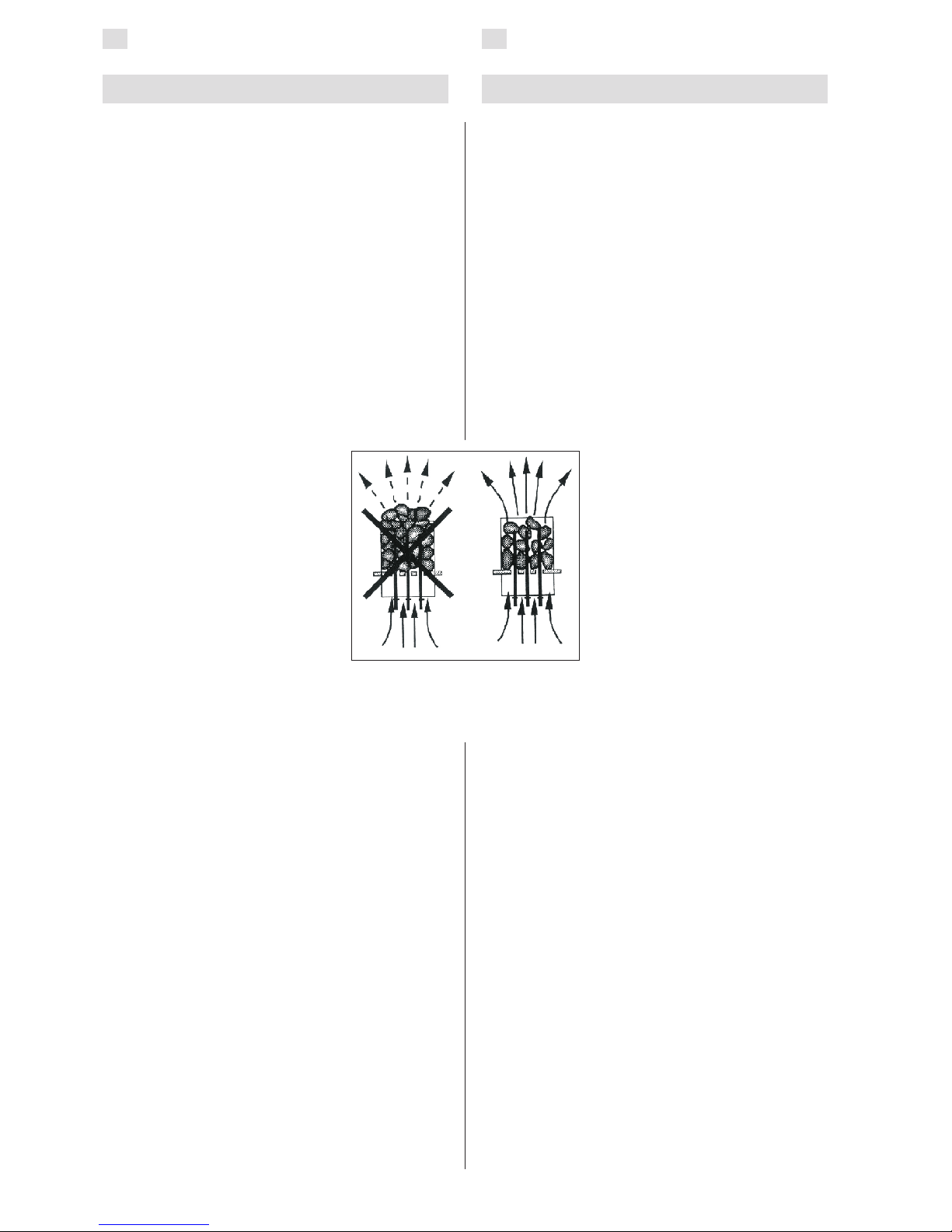
The stones should not be piled too tightly, so
that air can flow through the heater. The stones
should be fitted loosely, and not wedged between
the heating elements. Very small stones should not
be put into the heater at all.
The stones should completely
cover the heating elements.
However, they should not form a
high pile on the elements. See fig. 1.
The stones disintegrate with
use. Therefore, they should be
rearranged at least once a year or
even more often if the sauna is in
frequent use. At the same time, any
pieces of stones should be removed
from the bottom of the heater,
and disintegrated stones should be
replaced with new ones.
The guarantee does not cover any
faults caused by the use of stones
not recommended by the plant.
Neither does the guarantee cover
any faults caused by disintegrated
or too small stones blocking the heater ventilation.
No such objects or devices should be placed inside
the heater stone space or near the heater that could
change the amount or direction of the air flowing
through the heater, thus causing the resistance
temperature to rise too high, which may set the
wall surfaces on fire!
1.2. Heating of the Sauna
When the heater is switched on for the first
time, both the heater and the stones emit smell.
To remove the smell, the sauna room needs to be
efficiently ventilated.
The purpose of the heater is to raise the
temperature of the sauna room and the sauna stones
to the required bathing temperature. If the heater
output is suitable for the sauna room, it will take
about an hour for a properly insulated sauna to
reach that temperature. See item 2.1., ”Insulation
an Wall Materials of the Sauna Room”. A suitable
temperature for the sauna room is about + 65 °C
– +80 °C.
1.1. Aufschichten der Saunaofensteine
Die passenden Steine für einen Elektrosaunaofen
haben einen Durchmesser von 4–8 cm. Als
Saunaofensteine sollten speziell für Saunaöfen
gedachte, bekannte, massive Bruchsteine verwendet
werden. Die Verwendung leichter, poröser und
gleichgroßer keramischer Steine ist verboten, da
durch sie die Widerstände überhitzt und beschädigt
werden können. Als Saunaofensteine dürfen auch
keine weichen Topfsteine verwendet werden.
Die Steine sollten vor dem Aufschichten von
Steinstaub befreit werden. Die Steine werden auf
den Rost in den Saunaofen in die Zwischenräume
der Heizelemente so gesetzt, daß die Steine einander
tragen. Das Gewicht der Steine darf nicht von den
Heizelementen getragen werden.
Die Steine dürfen nicht zu dicht gesetzt werden,
damit die Luftzirkulation nicht behindert wird.
Auch dürfen die Steine nicht eng zwischen den
Heizelementen verkeilt werden, die Steine sollten
locker gesetzt werden. Sehr kleine
Steine sollen nicht in den Saunaofen
gelegt werden.
Die Steine sollen die Heizelemente
vollständig bedecken, sie dürfen
aber nicht hoch über den Saunaofen
herausragen. Siehe Abb. 1.
Während des Gebrauchs werden
die Steine spröde. Aus diesem
Grund sollten die Steine mindestens
einmal jährlich neu aufgeschichtet
werden, bei starkem Gebrauch
öfter. Bei dieser Gelegenheit
entfernen Sie bitte auch Staub und
Gesteinssplitter aus dem unteren
Teil des Saunaofens und erneuern
beschädigte Steine.
Die Garantie kommt nicht für
Schäden auf, die durch Verwendung anderer als
vom Werk empfohlener Saunaofensteine entstehen.
Die Garantie kommt auch nicht für Schäden des
Saunaofens auf, die durch Verstopfung der
Luftzirkulation durch bei Gebrauch spröde gewordene
Steine oder zu kleine Steine entstehen.
In der Steinkammer oder in der Nähe des
Saunaofens dürfen sich keine Gegenstände oder
Geräte befinden, die die Menge oder die Richtung
des durch den Saunaofen führenden Luftstroms
ändern, und somit eine Überhitzung der Widerstände
sowie Brandgefahr der Wandflächen verursachen!
1.2. Erhitzen der Saunakabine
Beim ersten Erwärmen sondern sich von Saunaofen
und Steinen Gerüche ab. Um diese zu entfernen,
muß die Saunakabine gründlich gelüftet werden.
Die Funktion des Saunaofens ist es, die Saunakabine und die Ofensteine auf die Aufgußtemperatur
zu bringen. Wenn die Leistung des Saunaofens an
die Größe der Saunakabine angepaßt ist, erwärmt
sich eine gut wärmeisolierte Sauna auf Aufgußtemperatur in etwa einer Stunde. Siehe Kapitel 2.1.
”Isolation der Saunakabine und Wandmaterialien”.
Die passende Temperatur in der Saunakabine beträgt
etwa +65 °C bis +80 °C.
Figure 1. Piling of the sauna
stones
Abbildung 1. Aufschichtung der
Saunaofensteine
Page 5

EN DE
5
The sauna stones normally reach the required
bathing temperature at the same time as the sauna
room. If the heater capacity is too big, the air
in the sauna will heat very quickly, whereas the
temperature of the stones may remain insufficient;
consequently, the water thrown on the stones
will run through. On the other hand, if the heater
capacity is too low for the sauna room, the room will
heat slowly and, by throwing water on the stones,
the bather may try to raise the temperature of the
sauna. However, the water will only cool down the
stones quickly, and after a while the sauna will not
be warm enough and the heater will not be able to
provide enough heat.
In order to make bathing enjoyable, the heater
capacity should be carefully chosen to suit the size
of the sauna room. See item 2.3. ”Heater Output”.
1.3. Controls of the heater and use
The JM20, JM25, JM30 heaters are equipped with
a timer and a thermostat.
The JM20E, JM25E and JM30E heaters must be
equipped with a separate control unit which must
be installed in a dry area outside of the sauna room.
Before you switch the heater on check always that
there aren’t any things over the heater or in the near
distance of the heater. See item 1.6. “Warnings”.
1.3.1. Heaters with timer and thermostat
(JM20, JM25, JM30)
Timer
The heater is switched on by using the timer switch.
The indicator lights will come on. The timer has
two scales: the first one (with larger figures) is
the ”instantly on” section; that is, the heater is
on for a selected period of time (0–4 hours). The
other section is the so called ”pre-set section” (1–8
hours), which is used to start the heater after a
certain time. The heater starts when the timer has
turned the switch back to the ”instantly on” section,
that is, at number four (4). After this, the heater will
be on for about 4 hours, unless the switch is turned
to zero before that. At zero (0), the supply to the
elements is cut off and the heater is switched off.
See fig 2.
Die Saunaofensteine erwärmen sich auf Aufgußtemperatur gewöhnlicht in derselben Zeit wie die
Saunakabine. Ein zu leistungsstarker Saunaofen erwärmt die Saunaluft schnell, aber die Steine bleiben
untererhitzt und lassen so das Aufgußwasser durchfließen. Wenn andererseits die Saunaofenleistung
in Bezug auf die Größe der Saunakabine gering ist,
erwärmt sich die Saunakabine langsam und der Saunabader wird versuchen, die Saunatemperatur durch
einen Aufguß (durch Gießen von Wasser auf den
Saunaofen) zu erhöhen. Das Aufgußwasser kühlt
aber nur die Saunaofensteine schnell ab und nach
einer Weile reicht die Temperatur in der Sauna nicht
mehr für einen Aufguß aus.
Damit Sie beim Saunen die Aufgüsse genießen
können, sollten Sie die Leistung des Saunaofens in
Bezug auf die Saunakabine anhand der Broschüreninformationen sorgfältig auswählen. Siehe Kapitel
2.3. ”Leistung des Saunaofens”.
1.3. Schaltmechanismus des Saunaofens
Die Typen JM20, JM25, JM30 sind mit einer Uhrschalter und einem Thermostat ausgestattet.
Die Typen JM20E, JM25E und JM30E werden mit
einem separaten Steuergerät bedient, das außerhalb
der Saunakabine an einem trockenen Ort angebracht
werden soll.
Bevor Sie den Ofen anschalten, bitte überprüfen,
dass keine Gagenstände auf dem Ofen oder in der
unmittelbarer Nähe des Ofens liegen. Siehe Kapitel
1.6. „Warnungen“.
1.3.1. Öfen mit Uhrschalter und Thermostat
(JM20, JM25, JM30)
Uhrschalter
Der Saunaofen wird durch das Drehen des Uhrschalters angeschaltet, die Skalalichter leuchten auf zum
Zeichen dafür, daß der Saunaofen angeschaltet ist.
Die Skala des Uhrschalters hat zwei Bereiche, von
denen der erste (größere Nummern) der ”Sofort Einschalten” -Bereich ist, der Saunaofen wird für die
einprogrammierte Zeit (0–4 Stunden) eingeschaltet.
Der zweite Bereich der Skala ist der sogenannte
Vorwahl- Bereich (1–8 Stunden). In diesem Bereich
erwärmt sich der Saunaofen nach einer gewünschten Wartezeit. Die Erwärmung beginnt, wenn der
Uhrmechanismus den Schalter bis auf den ”Sofort
Einschalten” –Bereich zurückgedreht hat, d.h. bis
auf die Nummer Vier (4). Danach ist der Saunaofen
für etwa 4 Stunden eingeschaltet, falls der Schalter
nicht schon früher auf die 0-Stellung zurückgedreht
wird, in der sich die Widerstandsströme abschalten
und sich der Saunaofen abkühlt. Siehe Abb. 2.
Figure 2. Control panel
Abbildung 2. Schalttafel
Page 6

EN DE
6
Example 1. You want to go jogging and have a
sauna bath after that. The estimated duration of
your run is 5 hours. Turn the timer clockwise over
the scale 0–4 to the pre-set section (scale 1–8) at
number 4.
The timer will start, and after four hours, the
heater will come on. Because it takes about one
hour for the sauna to be heated, it will be warm and
ready for bathing after about 5 hours, that is, when
you come back from your run.
Example 2. If you want to bathe ”immediately” and
thus do not want to use the pre-set timing, the timer
must be set to the desired point in the section 0–4.
Then, the heater will be switched immediately on
and the sauna will be ready for bathing after about
one hour.
Switch the heater off immediately after bathing
and check that the sauna stones are dry. Sometimes
it may be advisable to leave the heater on for a while
to let the wooden parts of the sauna dry properly.
NOTE! It is absolutely necessary to check that the
timer has cut off the supply of the elements after
the set time.
Thermostat and Overheating Limiter
The thermostat consists of two units; the adjustable
unit aims to
keep the temperature of the sauna room stable.
The temperature is adjusted by the thermostat to
a position between minimum and maximum. The
correct
position of the thermostat switch is found by
experimenting.
Begin experimenting at the maximum position (far
right) to find how quickly the sauna room and stones
can be heated to the desired temperature. If, during
bathing, the temperature seems to be becoming
too high, turn it down a little by turning the switch
counter-clockwise. It must be noted that even a
small difference within the maximum section will
change the temperature of the sauna considerably.
If, for some reason, the temperature of the sauna
room becomes too high, the overheating limiter of
the thermostat will permanently cut off the supply
of the resistances. The overheating limiter cannot
be reset to the position allowing electricity into the
thermostat until the heater has cooled down. The
overheating limiter is reset by pressing the reset
button of the thermostat, which is located in the
connection box inside the heater. Only persons
authorised to carry out electrical installations can
reset the overheating limiter. See fig. 3.
Beispiel 1. Eine Person möchte eine Wanderung
unternehmen und danach in die Sauna gehen. Die
Wanderung dauert etwa 5 Stunden. Der Uhrschalter
der Sauna muß also im Uhrzeigersinn über den Funktionsbereich (Skala 0–4) hinaus auf den VorwahlBereich (Skala 1–8) auf Nummer 4 gedreht werden.
Die Uhr läuft und nach vier Stunden schaltet sich
der Saunaofen an und erwärmt sich. Da die Erwärmungszeit der Sauna etwa eine Stunde beträgt,
ist die Sauna in etwa 5 Stunden warm, also genau
dann, wenn die Person von der Wanderung wieder
zurück ist.
Beispiel 2. Wenn eine Person ”sofort” in die Sauna gehen möchte, also nicht die Vorwahlfunktion
verwenden möchte, muß der Uhrschalter auf die
gewünschte Nummer im Funktionsbereich (0–4) eingestellt werden. Somit schaltet sich der Saunaofen
sofort ein, die Sauna erwärmt sich und ist in etwa
einer Stunde für den Badenden bereit.
Der Saunaofen sollte gleich ausgeschaltet werden, nachdem das Saunen beendet wurde und die
Sauna-ofensteine getrocknet sind. Manchmal ist es
jedoch erforderlich, den Ofen für eine kurze Zeit eingeschaltet zu lassen, damit die Holzteile der Sauna
trocknen.
ACHTUNG! Es ist darauf zu achten, daß der Uhrschalter der Sauna die Widerstandsströme des Saunaofens nach der eingestellten Zeit ausgeschaltet
hat.
Thermostat und Überhitzungsschutz
Das Thermostat besteht aus zwei Funktionseinheiten, von denen die regelbare Einheit bestrebt ist, die
eingestellte Temperatur in der Saunakabine stabil
zu halten.
Die Einregelung der Temperatur geschieht durch
Einstellen des Thermostats zwischen Minimum und
Maximun. Die richtige Einstellposition des Thermostats muß durch Probieren herausgefunden werden.
Beginnen Sie die Probe mit der maximalen Einstellposition des Reglers (rechter Anschlag), so erfahren
Sie, wie lange der Saunaofen mindestens braucht,
um die Sauna und die Saunaofensteine auf die gewünschte Temperatur zu erwärmen. Falls die Temperatur während des Saunens zu hoch ansteigt, muß
der Regler durch Drehen entgegen den Uhrzeigersinn
etwas kleiner eingestellt werden. Beachten Sie, daß
schon eine kleine Abweichung von der maximalen
Einstellposition eine spürbare Temperaturveränderung in der Saunakabine hervorruft.
Falls die Temperatur in der Saunakabine aus irgendeinem Grund zu hoch ansteigt, funktioniert
die Überhitzungsschutzeinheit des Thermostats als
Schutzvorrichtung und schaltet die Widerstandsströme des Saunaofens ab. Erst nach Abkühlung
des Saunaofens kann der Überhitzungsschutz in die
Stellung zurückgebracht werden, die den Stromfluß
durch das Thermostat ermöglicht. Zur Zurücksetzung des Überhitzungsschutzes ist am Thermostat
ein Rücksetzknopf angebracht, dieser befindet sich
im Schaltkasten des Saunaofens. Daher darf nur
eine zu Elektroinstallationen befugte Person diese
Arbeit ausführen. Siehe Abbildung 3.
Page 7

EN DE
7
Prior to pressing the button, the cause of the fault
must be found:
• Are the stones crumbled and pressed together?
• Has the heater been on for a long time while
unused?
• Is the sensor support of the thermostat bent
against the side of the stone compartment?
• Has the heater been banged or shaken?
1.3.2. Heaters with separate control units
(JM20E, JM25E, JM30E)
The JM20E, JM25E and JM30E heaters are
controlled from a separate control unit C90.
Install the heater and the sensor box, delivered
with the C90 control unit, according to these
instructions for installation and use. The control
unit has it’s own instructions.
1.4. Throwing Water on Heated Stones
The air in the sauna room becomes dry when
warmed up. Therefore, it is necessary to throw
water on the heated stones to reach a suitable level
of humidity in the sauna.
The humidity of the air in the sauna room is
controlled by the amount of water thrown on the
stones. A correct level of humidity makes the
bather’s skin sweat and makes breathing easy. By
throwing water on the stones with a small ladle, the
bather should feel the effect of air humidity on his
skin. Both too high a temperature and air humidity
will give an unpleasant feeling.
Staying in the hot sauna for long periods of time
makes the body temperature rise, which may be
dangerous.
The maximum volume of the ladle is 0,2 litres.
The amount of water thrown on the stones at a time
should not exceed 0,2 l, because if an excessive
amount of water is poured on the stones, only part
of it will evaporate and the rest may splash as boiling
hot water on the bathers.
Never throw water on the stones when there are
people near the heater, because hot steam may
burn their skin.
Vor Betätigung des Knopfes muß die Ursache der
Fehlfunktion festgestellt werden:
• Sind die Steine im Saunaofen verkeilt oder
spröde?
• War der Saunaofen lange angeschaltet und
wurde nicht benutzt?
• Ist die Halterung des Thermostatfühlers verbo-
gen und liegt an der Seitenwand des Saunaofens an?
• War der Saunaofen starken Stößen ausgesetzt?
1.3.2. Öfen mit separatem Steuergerät
(JM20E, JM25E, JM30E)
Die Öfen JM20E, JM25E und JM30E werden mit
einem separaten Steuergerät C90 bedient
Die Öfen und der Fühlerkasten, der mit dem Steuergerät C90 geliefert wird, werden laut dieser Gebrauchs- und Montageanleitung montiert. Mit dem
Steuergerät C90 wird eine separate Gebrauchs- und
Montageanleitung geliefert.
1.4. Aufguss
Die Saunaluft trocknet bei Erwärmung aus, daher
sollte zur Erlangung einer angenehmen Luftfeuchtigkeit auf die heißen Steine des Saunaofens Wasser
gegossen werden.
Mit der Wassermenge wird die für angenehm empfundene Aufgußfeuchtigkeit reguliert. Wenn die
Luftfeuchtigkeit passend ist, schwitzt die Haut des
Badenden und das Atmen in der Sauna fällt leicht.
Es empfiehlt sich, zunächst nur kleine Mengen Wasser auf die Steine zu gießen, damit die Wirkung der
Feuchtigkeit auf die Haut erprobt werden kann. Zu
hohe Temperaturen und Feuchtigkeitsprozente fühlen sich unangenehm an.
Ein langer Aufenthalt in einer heißen Sauna führt
zum Ansteigen der Körpertemperatur, was gefährlich sein kann.
Die Kapazität der Saunakelle sollte höchstens 0,2
l betragen. Auf die Steine sollten keine größeren
Wassermengen auf einmal gegossen werden, da
beim Verdampfen sonst kochend heißes Wasser auf
die Badenden spritzen könnte.
Achten Sie auch darauf, daß Sie kein Wasser auf
die Steine gießen, wenn sich jemand in deren Nähe
befindet. Der heiße Dampf könnte Brandwunden
verursachen.
Figure 3.
Abbildung 3.
Page 8

EN DE
8
1.4.1. Sauna Water
The water to be thrown on the heated stones should
meet the requirements of clean household water.
The factors essentially affecting the quality of water
include the following:
• Humuos content (colour, taste, precipitates);
recommended content less than 12 mg/litre.
• Iron content (colour, smell, taste, precipitates);
recommended content less than 0,2 mg/litre.
• Hardness – the most important substances
are manganese (Mn) and calcium (Ca);
recommended content of manganese 0,05 mg/
litre, calcium less than 100 mg/litre.
Calcareous water leaves a white, sticky layer
on the stones and metal surfaces of the heater.
Calcification of the stones deteriorates the heating
properties.
Ferrous water leaves a rusty layer on the surface
of the heater and elements, and causes corrosion.
The use of humous, chlorinated water and
seawater is forbidden.
Only special perfumes designed for sauna water
may be used. Follow the instructions given on the
package.
1.4.2. Temperature and Humidity of the Sauna
Room
Both thermometers and hygrometers suitable
for use in a sauna are available. As the effect of
steam on people varies, it is impossible to give an
exact, universally applicable bathing temperature or
percentage of moisture. The bather’s own comfort
is the best guide.
The sauna room should be equipped with proper
ventilation to guarantee that the air is rich in oxygen
and easy to breathe. See item 2.4. ”Ventilation of
the Sauna Room”.
Bathing in a sauna is considered a refreshing
experience and good for the health. Bathing cleans
and warms your body, relaxes the muscles, soothes
and alleviates oppression. As a quiet place, the
sauna offers the opportunity to meditate.
1.5. Instructions for Bathing
• Begin by washing yourself; for example, by
taking a shower.
• Stay in the sauna for as long as you feel
comfortable.
• According to established sauna conventions,
you must not disturb other bathers by speaking
in a loud voice.
• Do not force other bathers from the sauna by
throwing excessive amounts of water on the
stones.
• Forget all your troubles and relax.
• Cool your skin down as necessary.
• If you are in good health, you can have a swim
if a swimming place or pool is available.
• Wash yourself properly after bathing. Have
a drink of fresh water or a soft drink to bring
your fluid balance back to normal.
• Rest for a while and let your pulse go back to
normal before dressing.
1.4.1. Aufgußwasser
Als Aufgußwasser sollte nur Wasser verwendet
werden, das die Qualitätsvorschriften für Haushaltswasser erfüllt. Wichtige Faktoren für die Wasserqualität sind:
• Humusgehalt (Farbe, Geschmack, Ablagerun-
gen); Empfehlung unter 12 mg/l.
• Eisengehalt (Farbe, Geruch, Geschmack, Abla-
gerungen); Empfehlung unter 0,2 mg/l.
• Härtegrad; die wichtigsten Stoffe sind Mangan
(Mn) und Kalzium (Ca) oder Kalk; Empfehlung
für Mangan unter 0,05 mg/l und für Kalzium
unter 100 mg/l.
Bei Verwendung kalkhaltigen Wassers verbleibt auf
den Steinen und Metalloberflächen des Saunaofens
eine helle, cremeartige Schicht. Die Verkalkung der
Steine schwächt die Aufgußeigenschaften ab.
Bei Verwendung eisenhaltigen Wassers verbleibt
auf der Ofenoberfläche und den Widerständen eine
rostige Schicht, die Korrosion verursacht.
Die Verwendung von humus- und chlorhaltigem
Wasser sowie von Meerwasser ist verboten.
Im Aufgußwasser dürfen nur für diesen Zweck
ausgewiesene Duftstoffe verwendet werden. Befolgen Sie die Anweisungen auf der Packung.
1.4.2. Temperatur und Feuchtigkeit in der
Saunakabine
Zur Messung der Temperatur und Feuchtigkeit gibt
es Meßgeräte, die für den Gebrauch in einer Sauna
geeignet sind. Es ist allerdings unmöglich, allgemeingültig und genau die zum Saunen geeigneten Temperaturen oder Feuchtigkeitsprozente zu nennen,
da jeder Mensch die Wirkung des Aufgusses in der
Sauna anders empfindet. Das eigene Empfinden ist
das beste Thermometer des Badenden!
Eine sachgemäße Ventilation in der Sauna ist
wichtig, denn die Saunaluft muß sauerstoffreich und
leicht zu atmen sein. Siehe Kapitel 2.4. ”Ventilation
in der Saunakabine”.
Menschen empfinden das Saunen als gesund und
erfrischend. Das Saunen säubert, erwärmt, entspannt, beruhigt, lindert psychische Bedrücktheit
und bietet als ruhiger Ort die Möglichkeit zum Nachdenken.
1.5. Anleitungen zum Saunen
• Waschen Sie sich vor dem Saunen. Eine Du-
sche dürfte genügen.
• Bleiben Sie dann in der Sauna, solange Sie es
als angenehm empfinden.
• Zu guten Saunamanieren gehört, daß Sie Rück-
sicht auf die anderen Badenden nehmen, indem
Sie diese nicht mit unnötig lärmigem Benehmen
stören.
• Verjagen Sie die anderen auch nicht mit zu
vielen Aufgüssen.
• Vergessen Sie jeglichen Streß, und entspannen
Sie sich.
• Lassen Sie Ihre erhitzte Haut zwischendurch
abkühlen.
• Falls Sie gesund sind, und die Möglichkeit dazu
besteht, gehen Sie auch schwimmen.
• Waschen Sie sich nach dem Saunen. Nehmen
Sie zur Rückgewinnung der verlorenen Flüssigkeit ein erfrischendes Getränk zu sich.
• Ruhen Sie sich aus, bis Sie sich ausgeglichen
fühlen und ziehen Sie sich an.
Page 9

EN DE
9
1.6. Warnings
• Sea air and a humid climate may corrode the
metal surfaces of the heater.
• Do not hang clothes to dry in the sauna, as this
may cause a risk of fire. Excessive moisture
content may also cause damage to the
electrical equipment.
• Keep away from the heater when it is hot. The
stones and outer surface of the heater may
burn your skin.
• Do not throw too much water on the stones.
The evaporating water is boiling hot.
• Do not let young, handicapped or ill people
bathe in the sauna on their own.
• Consult your doctor about any health-related
limitations to bathing.
• Parents should keep children away from the
hot heater.
• Consult your child welfare clinic about taking
little babies to the sauna.
- age?
-temperature of the sauna?
-time spent in the warm sauna?
• Be very careful when moving in the sauna, as
the platform and floors may be slippery.
• Never go to a hot sauna if you have taken
alcohol, strong medicines or narcotics.
1.7. Troubleshooting
If the heater does not heat, check the following
points:
• The electricity has been switched on
• The timer has been switched to a section
where the heater should be heated (0–4).
• The thermostat shows a higher figure than the
temperature of the sauna.
• The fuses to the heater are in good condition.
• The temperature guard has not gone off. The
timer sound is heard but the elements are not
heated.
• Error messages of the control centre C90 – see
seperate instructions of the centre
• Reset the overheating limiter to its functioning
position by pressing it (if necessary, with the
power of 7 kilograms) so that a clicking sound
is heard. See item 1.3.1., ”Thermostat and
Overheating Limiter”.
1.6. Warnungen
• Meer- und feuchtes Klima können die Metal-
loberflächen des Saunaofens rosten lassen.
• Benutzen Sie die Sauna wegen der Brandge-
fahr nicht zum Kleider- oder Wäschetrocknen,
außerdem können die Elektrogeräte durch die
hohe Feuchtigkeit beschädigt werden.
• Achtung vor dem heißen Saunaofen. Die Steine
sowie das Gehäuse werden sehr heiß und können die Haut verbrennen.
• Auf die Steine darf nicht zuviel Wasser auf ein-
mal gegossen werden, da das auf den heißen
Steinen verdampfende Wasser die Haut verbrennen kann.
• Kinder, Gehbehinderte, Kranke und Schwache
dürfen in der Sauna nicht alleingelassen werden.
• Gesundheitliche Einschränkungen bezogen auf
das Saunen müssen mit dem Arzt besprochen
werden.
• Eltern dürfen ihre Kinder nicht in die Nähe des
Sauna ofens lassen.
• Über das Saunen von Kleinkindern sollten Sie
sich in der Mütterberatungsstelle beraten lassen.
- Alter? - Saunatemperatur? - Saunadauer?
• Bewegen Sie sich in der Sauna mit besonderer
Vorsicht, da die Bänke und der Fußboden glatt
sein können.
• Gehen Sie nicht in die Sauna, wenn Sie unter
dem Einfluß von Narkotika (Alkohol, Medikamenten, Drogen usw.) stehen.
1.7. Störungen
Falls sich der Saunaofen nicht erwärmt, überprüfen
Sie folgende Punkte:
• Strom ist eingeschaltet.
• Der Uhrschalter ist auf den Bereich (0–4) ge-
stellt, in dem sich der Saunaofen erwärmt.
• Das Thermostat ist auf eine höhere als in der
Sauna herrschende Temperatur eingestellt.
• Die Sicherungen des Saunaofens sind heil.
• Der Temperaturschutz ist nicht entriegelt wor-
den. In dieser Situation hört man die Uhr, aber
die Widerstände erwärmen sich nicht.
• Die Störungsanzeige des Steuergeräts C90 –
siehe Anleitung des Steuergeräts
• Der Schutz wird durch Drücken in seine Funk-
tionsstellung zurückgebracht (bei Bedarf mit
einer Kraft, die 7 kg entspricht), vom Schutz
ist ein Knacken zu hören. Siehe Kapitel 1.3.1.
”Thermostat und Überhitzungsschutz”.
Page 10

EN DE
10
2. SAUNAKABINE2. THE SAUNA ROOM
2.1. Isolation der Saunakabine und
Wandmaterialien
In einer elektrisch beheizten Sauna müssen alle
massiven Wandflächen, die viel Wärme speichern
(Ziegel, Glasziegel, Mörtel o.ä.) ausreichend isoliert
werden, um mit einer relativ geringen Leistung des
Saunaofens auszukommen.
Für gut isoliert kann man eine solche Sauna halten, die mit folgender Wand- und Deckenstruktur
ausgestattet ist:
• Die Dicke der sorgfältig gelegten Isolierwolle
beträgt auch im Hausinneren 100 mm (min. 50
mm).
• Als Feuchtigkeitssperre wird z.B. Aluminiumpa-
pier verwendet, dessen Ränder sorgfältig dicht
gefaltet werden und das so angebracht wird,
daß die glänzende Seite zum Inneren der Sauna
zeigt.
• Zwischen Feuchtigkeitssperre und Paneelen be-
findet sich (empfehlenswert) ein 10 mm großer
Entlüftungsspalt.
• Als Innenbeschichtung werden leichtgewichtige
Paneelbretter verwendet, die eine Dicke von
etwa 12–16 mm haben.
• Über der Wandverkleidung an der Grenze zu
den Deckenpaneelbrettern wird ein Entlüftungsspalt von einigen mm gelassen.
Um eine angemessene Saunaofenleistung zu erreichen, kann es erforderlich werden, die Saunadecke
weiter nach unten abzusenken (norm. 2100–230
mm, min. Saunahöhe 1900 mm), so daß der Rauminhalt der Sauna kleiner wird und eventuell eine
geringere Saunaofenleistung gewählt werden kann.
Die Absenkung der Decke wird durchgeführt, indem
man das Gebälk auf passender Höhe anbringt. Die
Balkenzwischenräume werden isoliert (Isolation mindestens 100 mm) und wird wie oben beschrieben
von innen verkleidet.
Da Wärme nach oben steigt, wird als Abstand zwischen Saunabank und Decke höchstens 1100–1200
mm empfohlen.
ACHTUNG! Zusammen mit einem Brandschutzbeamten muß festgestellt werden, welche Teile der
Brandmauer isoliert werden dürfen.
ACHTUNG! Der Schutz von Wänden oder der
Decke mit leichten Abdeckungen, z.B. Mineralplatten, die direkt an den Wand- oder Deckenflächen
befestigt werden, kann einen gefährlichen Temperaturanstieg in den Wand- und Deckenmaterialien
verursachen.
2.1.1. Verfärbung der Saunawände
Die Holzmaterialien in der Sauna, wie z.B. die Holzverkleidungen, verfärben sich mit der Zeit dunkel.
Dieser Prozess wird durch das Sonnenlicht und die
Hitze des Saunaofens beschleunigt. Wurden die
Wandverkleidungen mit einem speziellen Schutzmittel behandelt, kann die Verfärbung der Wand über
dem Ofen je nach verwendetem Schutzmittel relativ
schnell beobachtet werden. Diese Verfärbungen entstehen dadurch, dass die Schutzmittel eine geringere Hitzebeständigkeit aufweisen als unbehandeltes
Holz. Dies hat sich in Praxistests herausgestellt. Die
Mikromineralstoffe, die sich von den Steinen auf
2.1. Insulation and Wall Materials of the
Sauna Room
In an electrically heated sauna, all the massive wall
surfaces which store plenty of heat (such as bricks,
glass blocks, plaster etc.), must be sufficiently
insulated in order to keep the heater output at a
reasonably low level.
A wall and ceiling construction can be considered
to have efficient thermal insulation if:
• The thickness of carefully fitted insulating wool
inside the house is 100 mm (minimum 50 mm).
• The moisture protection consists of e.g.
aluminium paper with tightly taped edges. The
paper must be fitted so that the glossy side is
towards the inside of the sauna.
• There is a 10 mm vent gap between the
moisture protection and panel boards
(recommendation).
• The inside is covered by 12–16 mm thick
panelling.
• There is a vent gap of a few millimetres at the
top of the wall covering at the edge of the
ceiling panelling.
When aiming at a reasonable heater output,
it may be advisable to lower the ceiling of the
sauna (normally 2100–2300 mm, minimum height
1900 mm). As a result, the volume of the sauna
is decreased, and a smaller heater output may be
sufficient. The ceiling can be lowered so that the
ceiling joists are fixed at a suitable height. The spaces
between the joists are insulated (minimum insulation
100 mm) and surfaced as described above.
Because heat goes upwards, a maximum distance
of 1100–1200 mm is recommended between the
bench and ceiling.
NOTE! Consult fire-extinguishing authorities to
find out which part of the fireproof wall may be
insulated.
NOTE! The protection of the walls or ceiling with
heat protection, such as mineral board fitted directly
on the wall or ceiling, may cause the temperature
of the wall and ceiling materials to rise dangerously
high.
2.1.1. Blackening of the sauna walls
Wooden material in a sauna, such as panels, blackens
with age. The blackening process is sped up by
sunlight and the heat from the heater. If the wall
surfaces have been processed with protective panel
agents, the blackening of the surface of the wall
above the heater can be seen quite quickly depending
on the protective agent used. The blackening is due
to the fact that the protective agents have less
resistance to heat than unprocessed wood do. This
has been proven in practical tests. The micronic
mineral aggregate that crumbles from the stones
on the heater may blacken the wall surface near
Page 11

EN DE
11
the heater.
When following the manufacturer’s approved
guidelines in the installation of the sauna heater,
the heater will not heat up enough to endanger the
flammable material in the sauna room. The maximum
temperature allowed in the wall and ceiling surfaces
of the sauna room is +140 degrees Celsius.
Sauna heaters equipped with CE signs meet all
of the regulations for sauna installations. Proper
authorities monitor that the regulations are being
followed.
2.2. Sauna Room Floor
Due to a large variation in temperature, the sauna
stones disintegrate in use.
Small pieces of stone are washed down on the
sauna room floor along with the water thrown on
the stones. Hot pieces of stone may damage plastic
floor coverings installed underneath and near the
heater.
A light-cocoured joint grout, used for a tiled floor,
may absorb impurities from the stones and water
(e.g iron content).
To prevent aesthetic damage (due to the reasons
presented above) only dark joint grouts and floor
coverings made of rock materials should be used
underneath and near the heater.
2.3. Heater Output
When the walls and ceiling are covered with panels,
and the insulation behind the panels is sufficient
to prevent thermal flow into the wall materials,
the heater output is defined according to the cubic
volume of the sauna. See table 1.
If the sauna has visible uninsulated wall surfaces,
such as walls covered with brick, glass block,
concrete or tile, each square metre of said wall
surface causes the cubic volume of the sauna to
increase by 1,2 m3. The heater output is then
selected according to the values given in the table.
dem Ofen ablösen, können die Wandoberfläche in
der Nähe des Ofens dunkel verfärben.
Wenn Sie bei der Installation des Saunaofens die
vom Hersteller empfohlenen Richtlinien einhalten,
erhitzt sich der Saunaofen nur so weit, dass keine
Gefahr für die brennbaren Materialien der Saunakabine besteht. Die zulässige Höchsttemperatur für
die Wand- und Deckenoberflächen der Saunakabine
beträgt +140 oC.
Saunaöfen, die über ein CE-Symbol verfügen,
erfüllen alle Bestimmungen für Saunaanlagen. Die
entsprechenden Behörden kontrollieren, ob diese
Bestimmungen eingehalten werden.
2.2. Fußboden der Saunakabine
Aufgrund der großen Wärmeänderungen werden
die Saunasteine spröde und brüchig.
Steinsplitter und feine Gesteinsmaterialien werden mit dem Aufgußwasser auf den Saunafußboden
gespült. Heiße Steinsplitter können kunststoffbeschichtete Fußbodenbeläge unter dem Saunaofen
und in dessen unmittelbarer Nähe beschädigen.
Unreinheiten der Saunasteine und des Aufgußwassers (z.B. Eisengehalt) können von hellen Fugenmaterialien gekachelter Fußböden aufgesogen werden.
Um die Entstehung ästhetischer Mängel (aus oben
genannten Gründen) zu verhindern, sollten unter
dem Saunaofen und in dessen unmittelbarer Nähe
steinhaltige Fußbodenbeschichtungen und dunkle
Fugenmaterialien verwendet werden.
2.3. Leistung des Saunaofens
Wenn die Wände und die Decke getäfelt sind und
die Wärmeisolation hinter den Paneels ausreichend
ist, um das Entweichen der Wärme in die Wandmaterialien zu verhindern, hängt die erforderliche
Leistung des Ofens von der Größe des Innenraumes
Ihrer Sauna ab (siehe Tabelle 1).
Falls in der Sauna unisolierte Wandflächen wie
Ziegel-, Glasziegel-, Glas-, Beton- oder Kachelflächen
sichtbar sind, sollte für jeden Quadratmeter dieser
Flächen 1,2 m3 zum Rauminhalt addiert, und aufgrund dieser Summe die entsprechende Ofenleistung
aus der Tabelle bestimmt werden.
Heater
Ofen
Model and dimensions
Modell und Maße
Output
Leistung
Sauna room
Saunakabine
Connecting cable/Fuse
Cubic vol.
Rauminhalt
Height
Höhe
400V2N~ 230V1N~
Cable
Kabel
Fuse
Sicherung
Cable
Kabel
Fuse
Sicherung
Width/Breite
300/245(E) mm
Depth/Tiefe
220 mm
Height/Höhe
540 mm
Weight/Gewicht
9 kg
Stones/Steine
max. 8 kg
kW min
mm
3
max
mm
3
min
mm
mm
2
A mm
2
A
JM20, JM20E 2 1.2 2.0 1500 4 x 1,5 2 x 10 3 x 1,5 10
JM25, JM25E 2.5 1.5 2.5 1500 4 x 1,5 2 x 10 3 x 2,5 16
JM30, JM30E 3 2.0 4.0 1500 4 x 1,5 2 x 10 3 x 2,5 16
Table 1. Installation details of JM- and JME-heaters
Tabelle 1. Montageinformationen zur JM- und JME-Saunaöfen
Page 12

EN DE
12
Because log walls are heated slowly, the cubic
volume of a log sauna should be multiplied by 1,5,
and the heater output should then be selected on
the basis of this information.
2.4. Ventilation of the Sauna Room
Sufficient ventilation is extremely important for the
sauna. The air in the sauna room should be changed
six times per hour. The fresh air pipe should come
directly from outside. According to the newest
research results, the pipe should be located at a
minimum height of 50 cm above the heater. The
pipe diameter should be about 5–10 cm.
Exhaust air should be led from the lower part of
the sauna directly into the air chimney, or, by using
an exhaust pipe starting near the floor level, into
a vent in the upper part of the sauna. Exhaust air
can also be led out through an exhaust air vent in
the washing room through a 5 cm opening under
the sauna door. The exhaust air of the sauna room
should be taken from as far from the heater as
possible, but near the floor level. The crosscut area
of the exhaust air vent should be twice that of the
supply air pipe.
For the above-mentioned system, mechanical
ventilation is necessary.
If the heater is mounted in a ready-made sauna,
the instructions of the sauna manufacturer should
be followed when arranging ventilation.
The series of pictures shows examples of
ventilation systems for a sauna room. See fig. 4.
Saunas mit Blockbohlenwänden erwärmen sich
langsam, so daß man bei der Bestimmung der Ofenleistung den Rauminhalt dieser Saunas mit 1,5 multiplizieren sollte.
2.4. Ventilation in der Saunakabine
Besonders wichtig für das Saunen ist eine gute
Ventilation. Die Luft in der Saunakabine sollte in
der Stunde sechsmal wechseln. Das Frischluftrohr
sollte direkt von draußen kommen und sollte nach
neustem Stand der Forschungen über dem Saunaofen in mindestens 50 cm Höhe angebracht werden.
Der Durchmesser des Rohres sollte ca. 5–10 cm
betragen.
Die Abluft sollte aus dem unteren Teil der Sauna
direkt in einen Abzug oder durch ein knapp über
dem Saunaboden beginnendes Abzugsrohr zu einem
Ventil im oberen Teil der Sauna geleitet werden. Die
Abluft kann auch unter der Tür hindurch nach außen
geleitet werden, wenn sich unter der Tür, die zum
Waschraum mit Abluftventil führt, ein etwa 5 cm
breiter Spalt befindet. Die Abluft der Saunakabine
sollte möglichst weit entfernt vom Saunaofen aber
so nahe wie möglich am Fußboden abgeführt werden. Die Querschnittsfläche des Abzugsrohres sollte
zweimal größer als die des Frischluftrohres sein.
Die oben erwähnte Ventilation funktioniert, wenn
sie maschinell verwirklicht wird.
Falls der Saunaofen in eine Fertigsauna eingebaut
wird, müssen die Ventilationsanweisungen des Saunaherstellers befolgt werden.
In der Abbildungsserie sind Beispiele für Ventilationsstrukturen dargestellt. Siehe Abb. 4.
Figure 4. Ventilation of the sauna room
Abbildung 4. Ventilation in der Saunakabine
1. Air supply vent.
2. Optional air supply vent, if mechanical exhaust ventilation is used. The opening is located 50 cm above the
heater.
3. Exhaust air vent.
4. Possible drying valve, which is closed during heating and
bathing. The sauna can also be dried by leaving the door
open after bathing.
5. If there is an exhaust vent in the washing room only,
there should be a minimum 5 cm opening under the sauna room door. Mechanical ventilation is recommended.
1. Luftzufuhröffnung
2. Alternative Luftzufuhröffnung, wenn die Abluftventilation
maschinell erfolgt. Die Öffnung befindet sich 50 cm über
dem Saunaofen.
3. Abluftöffnung
4. Mögliches Trocknungsventil, das während der Erwärmung und des Saunens geschlossen ist. Die Sauna kann
auch getrocknet werden,indem die Tür nach dem Saunen
offengelassen wird.
5. Falls nur im Waschraum eine Abluftöffnung vorhanden
ist, sollte der Schwellenspalt der Saunatür mindestens
5 cm breit sein. Eine maschinelle Luftabfuhr ist dann
unerläßlich.
Page 13

EN DE
13
2.5. Hygiene in der Saunakabine
Damit das Saunen angenehm ist, muß für die Hygiene in der Saunakabine gesorgt werden.
Wir empfehlen in der Sauna auf Saunatüchern zu
sitzen, damit der Schweiß nicht auf die Bänke läuft.
Nach Gebrauch sollten die Saunatücher gewaschen
werden. Für Gäste sollten Sie eigene Saunatücher
bereithalten.
In Verbindung mit der Reinigung der Sauna sollte
der Fußboden der Saunakabine gesaugt / gefegt und
mit einem feuchten Lappen gewischt werden.
Mindestens jedes halbe Jahr sollte die Sauna
gründlich geputzt werden. Die Wände, Bänke und
der Fußboden der Saunakabine sollten mit einer
Bürste und mit Saunareinigungsmittel abgewaschen
werden.
Vom Saunaofen werden Staub und Schmutz mit
einem feuchten Tuch abgewischt.
2.5. Hygienic Conditions of the Sauna Room
Good hygienic standards of the sauna room will
make bathing a pleasant experience.
The use of sauna seat towels is recommended to
prevent sweat from flowing onto the platforms. The
towels should be washed after each use. Separate
towels should be provided for guests.
It is advisable to vacuum or sweep the floor of the
sauna room in connection with cleaning. In addition,
the floor may be wiped with a damp cloth.
The sauna room should be thoroughly washed at
least every six months. Brush the walls, platforms
and floor by using a scrubbing-brush and sauna
cleanser.
Wipe dust and dirt from the heater with a damp
cloth.
Page 14

EN DE
14
Figure 6. Location of the
mounting rack of the
heater
Abbildung 6. Platz des
Montagegestells des
Saunaofens
3.1. Prior to Installation
Prior to installing the heater, study the instructions
for installation, as well as checking the following
points:
• Is the output and type of the heater suitable for
the sauna room? The cubic volumes given in
table 1 should be followed.
• Are there a sufficient number of high quality
sauna stones?
• Is the supply voltage suitable for the heater?
• The location of the heater fulfils the minimum
requirements concerning safety distances given
in fig. 5 and table 1.
It is absolutely necessary to ensure that the
installation is carried out according to these values.
Neglecting them can cause a risk of fire. Only one
electrical heater may be installed in the sauna room.
3.2. Fastening the Heater on a Wall
Note! Connect the heater connection cable before
you fasten the heater on the wall rack. See item
3.4.1.
The installation rack of the heater has been
fastened to the heater. Unscrew the locking screw
of the rack and detach the installation support from
the heater.
3.1. Vor der Montage
Bevor Sie den Saunaofen installieren, lesen Sie die
Montageanleitung und überprüfen Sie folgende Dinge:
• Ist der zu montierende Saunaofen in Leistung
und Typ passend für die Saunakabine? Die
Rauminhaltswerte in Tabelle 1 dürfen weder
über- noch unterschritten werden.
• Sind genug Saunaofensteine von guter Qualität
vorhanden?
• Ist die Netzspannung für den Saunaofen geeig-
net?
• Der Montageort des Ofens erfüllt die in Abb. 5
und Tabelle 1 angegebenen Sicherheitsmindestabtände.
Diese Abstände müssen unbedingt eingehalten
werden, da ein Abweichen Brandgefahr verursacht.
In einer Sauna darf nur ein Saunaofen installiert
werden.
3.2. Befestigung des Saunaofens an der Wand
Achtung! Befestigen Sie das Anschußkabel bevor
Sie den Ofen am Wandgestell befestigen Siehe Kapitel 3.4.1.
Das Montagegestell des Saunaofens ist am Saunaofen befestigt. Entfernen Sie die Verriegelungsschraube des Montagegestells und nehmen das Gestell vom Saunaofen ab.
Figure 5. Safety distances from the heater
Abbildung 5. Sicherheitsmindestabstände des
Saunaofens
3. INSTRUCTIONS FOR
INSTALLATION
3. ANLEITUNG FÜR DEN
INSTALLATEUR
150
540
min. 700
300
245(E)
min. 15min. 5 min. 5
min. 80
220
min.
Page 15

EN DE
15
1. Fasten the wall-mounting rack on the wall by
using the screws which come with the rack.
Observe the minimum safety distances given
in fig. 6. The fastening of the mounting rack is
shown in fig. 6.
NOTE! There must be a support, e.g. a board,
behind the panel, so that the fastening screws
can be screwed into a thicker wooden material
than the panel. If there are no boards behind
the panel, the boards can also be fastened on
the panel.
2. Lift the heater to the rack on the wall.
3. The steam distributor must always be fastened
on the wall side of the heater. To turn the
distributor, loosen the fastening screws and
then turn it.
3.3. Installation of the Heater in a Recess
The heater can be mounted in a recess with a
minimum height of 1900 millimetres. See fig. 7.
3.4. Safety Railing
If a safety railing is built around the heater, the
minimum distances given in fig. 5 and 8 must be
observed.
The safety distance given in fig. 8 is valid below
the upper part of the heater’s outer casing.
1. Befestigen Sie das Montagegestell mit den
dazu gelieferten Schrauben an der Wand und
beachten Sie die in Abb. 6 angeführten Sicherheitsmindestabstände. Die Anbringung
des Montagegestells ist in Abb. 6 dargestellt.
ACHTUNG! An den Stellen, an denen die Befestigungsschrauben an gebracht werden, muss
sich hinter den Paneelen als Stütze z.B. ein
Brett befinden, in dem die Schrauben fest sitzen. Falls sich hinter den Paneelen keine Bretter
befinden, können diese auch vor den Paneelen
angebracht werden.
2. Heben Sie den Saunaofen so auf das Gestell an
der Wand.
3. Der Aufgußleiter muß immer an der Rückwand
des Saunaofens befestigt sein. Um den Leiter
einzustellen, entfernen Sie dessen Befestigungsschrauben und stellen Sie den Leiter dann
ein.
3.3. Installation des Saunaofens in einer
Nische
Der Saunaofen kann in einer Wandnische angebracht werden, deren Höhe min.1900 mm beträgt.
Siehe Abb. 7.
3.4. Schutzgeländer
Falls um den Saunaofen ein Schutzgeländer gebaut
wird, muß dies unter Berücksichtigung der in Abb.
5 und 8 angegebenen Mindestsicherheitsabstände
geschehen.
Der Sicherheitsabstand beträgt unter dem oberen
Rand des Aussenmantels. Siehe Abb. 8.
Figure 7. Installation of the heater in a recess
Abbildung 7. Montage des Saunaofens in einer
Wandnische
Figure 8. Safety railing of the heater
Abbildung 8. Schutzgeländer des Saunaofens
Page 16

EN DE
16
Figure 10. Electrical connections of heater
(JM20, JM25, JM30)
Abbildung 10. Elektroanschlüsse des Saunaofens
(JM20, JM25, JM30)
OPTIONALE
STEUERUNG FÜR
ZUSATZHEIZUNG
Figure 8. Safety railing of the heater
Abbildung 8. Schutzgeländer des Saunaofens
1. Uhrschalter
2. Thermostat
3. Klemmdose
4. Anschlußgehäuse
5. Rückstellknopf des
Temperaturbegrenzers im
Anschlußgehäuse
6. Anschlußkabel
7. Montagekabel
8. Tropfwasserschale
9. Holzschutzgitter
1. Timer
2. Thermostat
3. Junction box
4. Connection box
5. Temperature limit
reset button (inside)
6. Connection cable
7. Installation cable
8. Water cask
9. Wooden fence
Figure 9. Connections of the heater
Abbildung 9. Anschuß des Saunaofens
3.5. Electrical Connections
The heater may only be connected to the electrical
network in accordance with the current regulations
by an authorised, professional electrician.
The heater is semi-stationarily connected to the
junction box on the sauna wall. See fig. 9 and 10.
The connection cable must be of rubber cable type
H07RN-F or its equivalent.
NOTE!. Due to thermal embrittlement, the use
of PVC-insulated wire as the connection cable of
the heater is forbidden. The junction box must be
splash-proof, and its maximum height from the floor
must not exceed 50 cm.
If the connection and installation cables are higher
than 100 cm from the floor in the sauna or inside
the sauna room walls, they must be able to endure
a minimum temperature of 170 °C when loaded (for
example, SSJ). Electrical equipment installed higher
than 100 cm from the sauna floor must be approved
for use in a temperature of 125 °C (marking T125).
The cross-sectional area of the cable from the
control unit to the lights must be equal to the supply
cable of the control unit.
Further instructions concerning exceptional
installations can be obtained from local electrical
authorities.
3.5. Elektroanschlüße
Der Anschluß des Saunaofens ans Stromnetz darf nur
von einem zugelassenen Elektromonteur unter Beachtung der gültigen Vorschriften ausgeführt werden.
Der Saunaofen wird halbfest an die Klemmdose
an der Saunawand befestigt. Siehe Abb. 9 und 10.
Als Anschlußkabel wird ein Gummikabel vom Typ
H07RN-F oder ein entsprechendes Kabel verwendet.
ACHTUNG! PVC-isolierte Kabel dürfen wegen ihrer
schlechten Hitzebeständigkeit nicht als Anschlußkabel des Saunaofens verwendet werden. Die Klemmdose muß spritzwasserfest sein und darf höchstens
50 cm über dem Fußboden angebracht werden.
Falls der Anschluß oder die Montagekabel in die Sauna
oder die Saunawände in einer Höhe über 100 cm über
dem Boden münden, müssen sie belastet mindestens
eine Temperatur von 170 °C aushalten (z.B. SSJ). Elektrogeräte, die höher als 100 cm vom Saunaboden angebracht werden, müssen für den Gebrauch bei 125 °C
Umgebungstemperatur zugelassen sein (Vermerk T125).
Die Leitung vom Steuergerät zur Beleuchtung muß
vom Querschnitt her dem Netzkabel des Steuergeräts
entsprechen.
Genauere Anweisungen zu abweichenden Montagen
erhalten Sie von den für Elektroinstallationen verantwortlichen lokalen Behörden.
Page 17

EN DE
17
Figure 11. Electrical connections of heater (JM20E, JM25E, JM30E) and control unit C90
Abbildung 11 Elektroanschlüsse des Saunaofens (JM20E, JM25E, JM30E) und des Steuergerätes C90
Figure 12. Installation of the control unit on a wall
Abbildung 12. Installation des Steuergerätes an der Wand
Figure 13. Installation of the sensor
of C90 control unit
Abbildung 13. Installation des Fühlers
des Steuergerätes C90
3.5.1. Installation of the C90 control unit and
sensors (JM20E, JM25E, JM30E)
Install the control unit in a dry place outside the
sauna room at the height of about 170 cm. The
control unit may not be embedded into the wall.
See fig. 13. The control unit includes detailed
instructions for fastening the centre on the wall.
Install the temperature sensor on the wall of the
sauna room above the heater. It should be installed
on the lateral centre line of the heater, 100 mm
downwards from the ceiling. See fig. 14.
3.5.1. Anschluß des C90 Steuergerätes und der
Fühler (JM20E, JM25E, JM30E)
Das Steuergerät wird in einem trockenen Raum
außerhalb der Saunakabine in etwa 170 cm
Höhe angebracht. Das Steuergerät darf nicht in
Wandkonstruktion eingelassen werden. Siehe Abb.
13. In Verbindung mit dem Steuergerät werden
genauere Anweisungen zu dessen Befestigung an
der Wand gegeben.
Der Temperaturfühler wird an der Saunawand
oberhalb des Saunaofens, 100 mm unterhalb
der Decke auf der Achse in Breitenrichtung des
Saunaofens angebracht. Siehe Abb. 14.
Page 18

EN DE
18
ELECTRICAL HEATING
CONTROL/
OPTIONALE STEUERUNG
FÜR ZUSATZHEIZUNG
Figure 15. Electrical connections of JM heater in Norway
Abbildung 15. Elektroanschlüsse des JM Saunaofens in Norwegen
Figure 14. Electrical connections of JM heater in Japan
Abbildung 14. Elektroanschlüsse des JM Saunaofens in Japan
3.6. Electric heater insulation resistance
When performing the final inspection of the electrical installations, a “leakage” may be detected when
measuring the heater’s insulation resistance. The
reason for this is that the insulating material of the
heating resistors has absorbed moisture from the
air (storage transport). After operating the heater
for a few times, the moisture will be removed from
the resistors.
Do not connect the power feed for the heater
through the RCD (residual current device)!
3.6. Isolationswiderstand des
Elektrosaunaofens
Bei der Endkontrolle der Elektroinstallationen kann
bei der Messung des Isolationswiderstandes ein
“Leck” auftreten, was darauf zurückzuführen ist,
daß Feuchtigkeit aus der Luft in das Isolationsmaterial der Heizwiderstände eingetreten ist (bei Lagerung
und Transport). Die Feuchtigkeit entweicht aus den
Widerständen nach zwei Erwärmungen.
Schalten Sie den Netzstrom des Elektrosaunaofens
nicht über den Fehlerstromschalter ein!
Page 19

EN DE
19
4. SPARE PARTS 4. ERSATZTEILE
1. Knob + Cap Knopf + Mütze ZSA-660
2. Scale plate Skalaplatte ZSA-670
3. Control box plastic part Steuerungeinheit aus Plastik ZSA-480
4. Wooden fence Holzschutzgitter ZSJ-190
5. Heating element 1000W/230V Heizelement 1000W/230V ZSJ-100
5. Heating element 1500W/230V Heizelement 1500W/230V ZSJ-110
6. Thermostat Thermostat ZSK-520
7. Timer 4 + 8h Schaltuhr 4 + 8h ZSK-510
8. Water cask Tropfwasserschale ZSJ-200
Page 20

ESIT
20
Figura 1. Come impilare le pietre
della sauna
1. ISTRUZIONI PER L’USO
1.2. Riscaldamento della sauna
Quando il riscaldatore viene acceso per la prima volta, sia il riscaldatore che le pietre rilasciano un certo
odore. Per eliminare questo odore, la stanza della
sauna deve essere ventilata in maniera sufficiente.
Scopo del riscaldatore è quello di aumentare la
temperatura della stanza della sauna fino ad ottenere
la temperatura ottimale per il bagno. Se la portata
del riscaldatore è adatta alla stanza della sauna,
il raggiungimento della suddetta temperatura richiederà all’incirca un’ora in una sauna convenientemente isolata. Vedi paragrafo 2.1., “Isolamento e
materiali per le pareti della stanza della sauna”. Per
una sauna, la temperatura ottimale è di circa +65
°C – +80 °C.
Le pietre della sauna raggiungono solitamente la
temperatura ottimale per il bagno contemporaneamente alla stanza stessa. Se la portata del riscaldatore è eccessiva, l’aria della sauna si riscalderà molto
in fretta mentre la temperatura delle pietre potrebbe
rimanere insufficiente e, di conseguenza, l’acqua che
viene gettata sulle pietre non farà altro che scivolare
via. D’altra parte, se la portata del riscaldatore è
troppo scarsa per la stanza della sauna, la stanza si
riscalderà lentamente e l’utilizzatore potrebbe tentare di aumentare la suddetta temperatura gettando
acqua sulle pietre. Ma l’acqua non farebbe altro che
far raffreddare rapidamente le pietre e dopo un po’ la
sauna non sarebbe più sufficientemente calda, né il
riscaldatore riuscirebbe a fornire abbastanza calore.
Per rendere gradevole il bagno, la portata del bruciatore dovrebbe essere scelta con attenzione, in
modo che sia adatta alle dimensioni della stanza
della sauna. Vedi paragrafo 2.3., “Portata del riscaldatore”.
1.3. Comandi della stufa e impiego
I modelli JM20, JM25 e JM30 sono dotati di timer
e termostato.
Le stufe JM20E, JM25E e JM30E devono disporre
di una centralina separata da installare in una zona
asciutta all’esterno della stanza della sauna.
Prima di accendere la stufa, controllare sempre
che non vi siano oggetti appoggiati sopra né a poca
distanza. Vedere punto 1.6. “Avvertimenti”.
1.3.1. Stufe con timer e termostato (JM20,
JM25, JM30)
Timer
Accendere la stufa con l’interruttore del timer: si
illuminano le spie. Il timer ha due scale graduate:
la prima (con numeri grandi) è la sezione “accensione immediata”, la stufa cioè rimane accesa per un
tempo stabilito (0-4 ore), mentre l’altra è la cosiddetta “sezione preimpostata” (1-8 ore), utilizzata per
accendere la stufa dopo un periodo determinato. La
stufa parte quando il timer ha riportato l’interruttore
alla sezione “accensione immediata”, cioè al numero quattro (4), dopo di che resterà accesa per
circa quattro ore, a meno che l’interruttore non sia
stato prima azzerato. Sullo zero (0), l’alimentazione
elettrica agli elementi è staccata e la stufa è spenta.
Vedere figura 2.
1.1. Come impilare le pietre da sauna
Le pietre da sauna per un bruciatore elettrico dovrebbero avere un diametro di 4–8 cm. Le pietre per il
riscaldatore dovrebbero essere blocchi solidi di pietra
particolarmente indicata per l’utilizzo nel riscaldatore. Non bisogna utilizzare né “pietre” leggere e porose di ceramica, anche se delle stesse dimensioni,
né pietre argillose morbide, perché potrebbero far sì
che la temperatura di resistenza aumenti troppo e ciò
potrebbe portare alla rottura della resistenza stessa.
Prima di impilare le pietre è bene lavare via la
loro polvere. Le pietre dovrebbero essere impilate
nello scomparto riservato alle pietre e posto sopra la
griglia, fra gli elementi elettrici (resistenze), in modo
che le pietre si sostengano a vicenda. Il peso delle
pietre non deve poggiare sugli elementi di riscaldamento.
Le pietre non devono essere troppo strette fra loro,
in modo che l’aria possa circolare attraverso il riscaldatore. Vedi fig. 1. Le pietre vanno impilate senza
fare pressione e non vanno incuneate fra gli elementi
del riscaldatore. Non bisogna assolutamente inserire
pietre molto piccole.
Le pietre dovrebbero coprire completamente gli
elementi di riscaldamento, pur non formando una
pila troppo alta sopra di essi.
Con l’andare del tempo, le pietre tendono a sbriciolarsi. Di conseguenza esse vanno risistemate perlomeno una volta all’anno, o anche più spesso, se
la sauna viene usata con una certa frequenza. Allo
stesso tempo, ogni frammento di pietra deve essere
tolto dal fondo del riscaldatore, e le pietre sbriciolate
devono essere sostituite da altre.
La garanzia non copre i guasti provocati dall’utilizzo
di pietre non consigliate dalla ditta, come pure i
guasti provocati dalla presenza di pietre sbriciolate
o troppo piccole che vadano a bloccare il sistema di
ventilazione del riscaldatore.
E’ importante che nessun oggetto od apparecchio
venga posto all’interno dello spazio del riscaldatore
riservato alle pietre, né presso il riscaldatore, affinché la quantità e la direzione del flusso dell’aria
attraverso il riscaldatore non subiscano variazioni.
Ciò infatti potrebbe causare un eccessivo aumento
della temperatura di resistenza e far prendere fuoco
alle pareti!
Page 21

ES21IT
Figura 3.
premere il pulsante di reset del termostato, ubicato nella scatola di derivazione dentro la stufa, ma
solo personale autorizzato ad eseguire installazioni
elettriche può eseguire l’operazione. Vedere il punto
3.5. e la figura 15.
Prima di premere il pulsante, occorre stabilire la
causa dell’anomalia:
• Le pietre sono sbriciolate e pressate le une
contro le altre?
• La stufa è rimasta accesa per molto tempo
senza essere utilizzata?
• Il supporto del sensore del termostato è inclina-
to contro il lato dello scomparto per le pietre?
• La stufa ha ricevuto colpi o scosse?
1.3.2. Stufe con centralina separata (JM20E,
JM25E, JM30E)
Le stufe nei modelli JM20E, JM25E e JM30E sono
controllate dalla centralina separata C90.
Montare la stufa e la scatola dei sensori, fornita
in dotazione con la centralina C90, seguendo le
presenti istruzioni per l’installazione e l’utilizzo. Per
la centralina esiste un manuale di istruzioni distinto.
1.4. Come gettare l’acqua sulle pietre
riscaldate
L’aria della stanza della sauna diventa secca, una
volta riscaldata. Di conseguenza è necessario gettare dell’acqua sulle pietre riscaldate in modo da
ottenere un grado ottimale di umidità nella sauna.
E’ possibile regolare il grado di umidità dell’aria nel-
la stanza della sauna in base alla quantità dell’acqua
gettata sulle pietre. Un corretto grado di umidità
favorisce la sudorazione dell’utilizzatore e facilita
la respirazione. Gettando l’acqua sulle pietre per
mezzo di un piccolo mestolo, l’utilizzatore dovrebbe
sentire sulla pelle gli effetti dell’umidità dell’aria. Un
eccesso di temperatura o di umidità dell’aria dà una
sensazione spiacevole.
Una lunga permanenza in una sauna calda pro-
voca l’aumento della temperatura corporea, il che
potrebbe essere pericoloso.
Il volume massimo del mestolo è di 2 decilitri. La
quantità d’acqua da gettare sulle pietre non dovrebbe superare i 2 dl ogni volta, perché se si utilizza
una eccessiva quantità d’acqua solo una parte di
essa riuscirà ad evaporare ed il resto, trasformato in
acqua bollente, potrebbe schizzare sugli utilizzatori.
Esempio 1. Volete andare a correre e poi fare la
sauna. La durata stimata della corsa è di 5 ore. Girare il timer in senso orario sulla scala graduata 0-4
alla sezione di preimpostazione (1-8) sul numero 4.
Il timer parte e dopo quattro ore la stufa si accende. Dato che la sauna si scalda in circa un’ora,
la stanza sarà calda e pronta per l’uso dopo circa
cinque ore, al ritorno dalla corsa.
Esempio 2. Per fare la sauna “immediatamente” e
quindi non utilizzare l’opzione di preimpostazione,
il timer deve essere impostato al punto desiderato
nella sezione 0-4, così la stufa si accende subito e
la sauna sarà pronta per il bagno dopo circa un’ora.
Spegnere subito la stufa dopo il bagno e controllare che le pietre della sauna siano asciutte. Talvolta
può essere consigliabile lasciare la stufa accesa per
un po’ in modo che le parti in legno della sauna si
asciughino correttamente.
NOTA BENE: è assolutamente necessario verificare che il timer abbia sospeso l’alimentazione degli
elementi dopo il tempo stabilito.
Termostato e limitatore termico di sicurezza
Il termostato è costituito da due parti; l’unità regolabile ha lo scopo di mantenere stabile la temperatura
della stanza della sauna.
È il termostato che regola la temperatura in una
posizione compresa tra un minimo ed un massimo.
Per trovare la posizione corretta dell’interruttore del
termostato è necessario sperimentare.
Iniziare provando nella posizione massima (tutto a
destra), per verificare quanto tempo occorra per portare alla temperatura desiderata la stanza della sauna
e le pietre; se durante il bagno si ha la sensazione
che la temperatura si sia innalzata eccessivamente,
è possibile abbassarla un po’ girando l’interruttore
in senso antiorario. È opportuno notare che anche
una differenza minima nella sezione massima va a
modificare la temperatura della sauna in maniera
considerevole. Vedere fig. 3.
Nel caso che, per qualche motivo, la temperatura della sauna si alzi troppo, il limitatore termico
di sicurezza del termostato stacca l’alimentazione
delle resistenze in maniera permanente e può essere resettato alla posizione che consente l’entrata
dell’elettricità solo a stufa raffreddata. Per ripristinare il limitatore termico di sicurezza, è necessario
Figura 2. Centralina
Page 22

ESIT
22
piscina.
• Dopo il bagno lavatevi accuratamente. Bevete
un po’ d’acqua fresca o un soft drink per ricostituire l’equilibrio dei liquidi nel vostro corpo.
• Riposatevi un po’ e attendete che le pulsazioni
riprendano il ritmo normale prima di rivestirvi.
1.6. Avvertenze
• L’aria di mare ed il clima umido possono cor-
rodere le superfici metalliche del riscaldatore.
• Non appendete vestiti ad asciugare nella sauna,
perché possono costituire un rischio di incendio. Inoltre, un contenuto eccessivo di umidità
può danneggiare l’impianto elettrico.
• State lontani dal riscaldatore quando è caldo.
Le pietre e le superfici esterne del riscaldatore
possono ustionare la pelle.
• Non gettate troppa acqua sulle pietre; l’acqua
che evapora è bollente e può scottarvi.
• Non permettete a persone giovani, handicap-
pate od ammalate di fare il bagno in sauna da
sole.
• Consultate il vostro medico relativamente ai
rischi che il bagno in sauna può comportare per
la vostra salute.
• I genitori devono tenere i bambini lontani dal
riscaldatore acceso.
• Consultate il vostro pediatra sull’opportunità di
portare bambini piccoli in sauna.
- età?
- temperatura della sauna?
- tempo trascorribile in una sauna calda?
• State molto attenti a muovervi all’interno della
sauna, perché la piattaforma ed il pavimento
possono essere scivolosi.
• Non entrate mai in una sauna calda se avete
assunto alcolici, medicinali forti o sostanze
stupefacenti.
1.7. Malfunzionamento
Se la stufa non riscalda, verificare i seguenti punti:
• l’elettricità è accesa
• il timer è stato girato su una sezione in cui la
stufa dovrebbe essere riscaldata (0–4).
• la cifra che compare sul termostato è più el-
evata rispetto alla temperatura della sauna.
• i fusibili per la stufa sono in buone condizioni.
(Nota: non sempre il perno si stacca quando il
fusibile salta).
• la protezione termica non è scattata. Si sente il
suono del timer ma gli elementi non sono caldi.
• messaggi d’errore della centralina C90 – vedere
istruzioni a parte per la centralina
• ripristinare il limitatore termico di sicurezza in
posizione di funzionamento premendolo (se
necessario, con una potenza di 7 kg) in modo
che sia percepibile un clic. Vedere posizione
1.3.1., “Termostato e limitatore termico di
sicurezza”
Non gettare mai l’acqua sulle pietre se ci sono persone in prossimità del riscaldatore, perché il getto di
vapore bollente potrebbe provocare ustioni alla pelle.
1.4.1. Acqua della sauna
L’acqua da gettare sulle pietre riscaldate dovrebbe
essere pulita come la normale acqua per utilizzo
domestico. Tra i fattori che influiscono sulla qualità
dell’acqua troviamo i seguenti:
• Contenuto di humus (colore, gusto, precipitati);
percentuale consigliata: inferiore a 12 mg/litro
• Contenuto di ferro (colore, odore, gusto, pre-
cipitati); percentuale consigliata: inferiore a 0,2
mg/litro
• Durezza: le sostanze principali sono manganese
(Mn) e calcio (Ca); percentuale consigliata: per
il
manganese 0,05 mg/litro, per il calcio inferiore
a 100 mg/litro.
L’acqua calcarea lascia uno strato bianco ed ap-
piccicoso sulle pietre e sulle superfici metalliche del
riscaldatore. La calcificazione delle pietre provoca
un deterioramento delle caratteristiche riscaldanti.
L’acqua ferrosa lascia uno strato rugginoso sulla
superficie e sugli elementi del riscaldatore, e provoca
corrosione.
E’ vietato utilizzare acqua ricca di humus e di cloro
oppure acqua marina.
E’ possibile utilizzare soltanto profumi speciali
appositamente prodotti per l’acqua della sauna.
Seguite le istruzioni fornite sull’imballo.
1.4.2. Temperatura ed umidità della stanza della
sauna
Sono disponibili sia i termometri che gli igrometri
adatti all’utilizzo in sauna. Dal momento che l’effetto
del vapore varia da persona a persona, è impossibile stabilire una temperatura per il bagno od una
percentuale di umidità che siano precise e valide in
maniera universale. La miglior guida rimane il piacere
provato dall’utilizzatore.
La stanza della sauna dovrebbe essere fornita
di un’adeguata ventilazione in modo da garantire
che l’aria sia ricca di ossigeno e facile da respirare.
Vedi paragrafo 2.4, “Ventilazione della stanza della
sauna”.
Il bagno in sauna viene considerato un’esperienza
corroborante e buona per la salute. Il bagno pulisce
e scalda il corpo, rilassa i muscoli, attenua ed allevia il senso di oppressione. Inoltre la sauna offre la
possibilità di meditare, essendo un posto tranquillo.
1.5. Istruzioni per il bagno
• Iniziate lavandovi il corpo, ad esempio facendo
una doccia.
• Restate nella sauna per tutto il tempo in cui vi
ci sentite a vostro agio.
• In base alle convenzioni stabilite per le saune,
non dovete disturbare gli altri bagnanti parlando
a voce alta.
• Non costringete gli altri bagnanti ad uscire dalla
sauna gettando una quantità eccessiva d’acqua
sulle pietre.
• Dimenticate tutti i vostri problemi e rilassatevi.
• Lasciate che la vostra pelle si rinfreschi per
tutto il tempo necessario.
• Se siete in buona salute, potete anche fare
una nuotata se è disponibile una vasca o una
Page 23

ES23IT
l’alto, si consiglia una distanza massima di 1100–
1200 mm fra la panca ed il soffitto.
NOTA: consultate i pompieri per sapere quale
parte del muro va isolata contro gli incendi. Non
isolate le canne fumarie.
NOTA: La protezione delle pareti o del soffitto
per mezzo di un isolante per il calore, come pannelli
metallici posti direttamente a contatto con le pareti
od il soffitto può provocare un pericoloso aumento
della temperatura dei materiali degli stessi.
2.1.1. Annerimento delle pareti della sauna
I componenti di legno di una sauna, quali ad esempio
i pannelli di rivestimento, con il passare del tempo
si anneriscono. Il processo di annerimento viene accelerato dalla luce del sole e dal calore emanato dalla
stufa. Se la superficie delle pareti è stata trattata con
agenti protettivi specifici per pannelli, l’annerimento
della superficie della parete al di sopra della stufa
potrà verificarsi in tempi più o meno brevi, a seconda
dell’agente protettivo utilizzato. Come dimostrano i
test pratici, l’annerimento è dovuto ad una resistenza al calore degli agenti protettivi inferiore a quella
del legno non trattato.
Il micronico aggregato minerale che si stacca
dalle pietre posate sulla stufa può essere la causa
dell’annerimento della parete nei pressi della stufa.
Attenendosi alle istruzioni approvate dal fabbricante per l’installazione della stufa si potrà evitare
che questa raggiunga una temperatura capace di
mettere a rischio le sostanze infiammabili all’interno
della sauna. La temperatura massima consentita
sulle superfici interne delle pareti e del soffitto è di
+140 °C.
Le stufe per sauna che recano il marchio CE sono
conformi alle disposizioni per gli impianti sauna. Le
autorità competenti vigilano sull’adempimento di
tali disposizioni.
2. LA STANZA DELLA SAUNA
2.1. Isolamento e materiali per le pareti della
stanza della sauna
In una sauna riscaldata elettricamente, tutte le superfici murarie massicce che immagazzinano parecchio
calore (come i mattoni, le parti in vetro, l’intonaco
etc.) devono essere correttamente isolate allo scopo
di mantenere la portata del riscaldatore ad un livello
ragionevolmente basso.
Una costruzione formata da pareti e soffitto può
essere considerata dotata di un corretto isolamento
termico se:
• Lo spessore della lana isolante accuratamente
inserita nell’edificio è di 100 mm (minimo 50
mm).
• La protezione contro l’umidità consiste, ad
esempio, in carta d’alluminio con i bordi perfettamente sigillati. La carta va sistemata in modo
che la parte lucida si trovi rivolta verso l’interno
della sauna.
• E’ stato lasciato uno spazio di 10 mm fra la
protezione contro l’umidità ed i pannelli (è consigliabile).
• L’interno della stanza è coperto da pannelli con
uno spessore di 12–16 mm.
• E’ stato lasciato uno spazio di alcuni millimetri
fra la parte finale del rivestimento delle pareti
ed il bordo del rivestimento del soffitto.
Se si desidera ottenere una ragionevole portata del
riscaldatore, potrebbe essere consigliabile abbassare
il soffitto della sauna (normalmente a 2100–2300
mm, altezza minima 1900 mm). In questo modo il
volume della sauna viene ridotto e sarà sufficiente
una portata inferiore del riscaldatore. Il soffitto va
abbassato in modo che i travetti del soffitto stesso
siano posti ad un’altezza corretta. Gli spazi fra un
travetto e l’altro vanno isolati (isolamento minimo:
100 mm) e rivestiti come sopra descritto.
Dal momento che il calore tende ad andare verso
Riscaldatore
Modello e Dimensioni
Portata Stanza della sauna Cavo collegament
Vol. cubico Altezza 400V2N~ 230V1N~
Cavo Fusibile Cavo Fusibile
Larghezza
300/245(E) mm
Profondità
220 mm
Altezza
540 mm
Peso
9 kg
Pietre
max. 8 kg
kW min
mm
3
max
mm
3
min
mm
mm
2
A mm
2
A
JM20, JM20E 2 1.2 2.0 1500 4 x 1,5 2 x 10 3 x 1,5 10
JM25, JM25E 2.5 1.5 2.5 1500 4 x 1,5 2 x 10 3 x 2,5 16
JM30, JM30E 3 2.0 4.0 1500 4 x 1,5 2 x 10 3 x 2,5 16
Tabella 1. Particolari relativi all’installazione, per stufe nei modelli JM e JME.
Page 24

ESIT
24
Figura 4. Ventilazione della stanza della sauna
1. Sfiatatoio di entrata dell’aria.
2. Sfiatatoio facoltativo di entrata dell’aria, se si adopera una ventilazione meccanica per lo scarico. L’apertura è posta 50 cm
al di sopra del riscaldatore.
3. Sfiatatoio di uscita dell’aria.
4. Possibile valvola di asciugatura, che va tenuta chiusa durante il riscaldamento ed il bagno. La sauna può essere asciugata
anche lasciando aperta la porta dopo il bagno.
5. Se uno sfiatatoio di uscita dell’aria è presente soltanto nella stanza dove ci si lava, dovrebbe essere effettuata anche
un’apertura minima di 5 centimetri sotto la porta della stanza della sauna. Si consiglia una ventilazione meccanica.
ad un’altezza minima di 50 cm sopra il riscaldatore ed
avere un diametro di circa 5–10 cm.
L’aria da espellere dovrebbe passare dalla parte inferiore della sauna direttamente alla canna fumaria
oppure, se si utilizza un tubo di scarico dell’aria quasi
a livello del suolo, ad uno sfiatatoio nella parte superiore della sauna. L’aria da espellere può essere
eliminata anche per mezzo di uno sfiatatoio di scarico
nella stanza da bagno, attraverso un’apertura di 5 cm
praticata sotto la porta della sauna. L’aria da espellere
dalla stanza della sauna dovrebbe essere prelevata
da un punto il più lontano possibile dal riscaldatore,
ma posto quasi a livello del suolo. L’apertura dello
sfiatatoio per l’aria di scarico dovrebbe essere doppia
rispetto a quella del tubo che fornisce aria fresca.
Per un sistema come quello sopra riportato è necessaria una ventilazione meccanica.
Se il riscaldatore viene montato in una sauna già predisposta, è necessario seguire le istruzioni fornite dal
produttore della sauna relativamente alla ventilazione.
Una serie di immagini mostra alcuni esempi di sistemi
di ventilazione per una stanza da sauna. Vedi fig. 2.
2.5. Condizioni igieniche della stanza della
sauna
L’esperienza del bagno verrà resa piacevole anche
dalle condizioni igieniche presenti nella stanza della
sauna.
L’uso di asciugamani sui sedili della sauna è consigliabile, affinché il sudore non coli direttamente
sui sedili stessi. Gli asciugamani dovrebbero essere
lavati dopo ogni utilizzo. E’ bene predisporre alcuni
asciugamani di scorta per gli ospiti.
Per pulire bene la sauna è consigliabile spazzare
il pavimento della stanza della sauna, o passarvi
l’aspirapolvere, e poi ripassare il pavimento con uno
straccio umido.
La stanza della sauna dovrebbe essere lavata da
cima a fondo perlomeno ogni sei mesi. Spazzolate
le pareti, le piattaforme ed il pavimento utilizzando
una spazzola e con un prodotto specifico per saune.
La polvere e lo sporco sul riscaldatore vanno eliminati con uno straccio umido.
2.2. Il pavimento della stanza della sauna
A causa degli enormi sbalzi di temperatura, le pietre
della sauna tendono a sbriciolarsi con l’uso.
I piccoli frammenti di pietra vengono trascinati
sul pavimento della sauna dall’acqua versata sulle
pietre. Questi sassolini roventi possono danneggiare
il rivestimento in plastica del pavimento installato
sotto e presso il riscaldatore.
Un intonaco plastico con frammenti di pietra,
come quello utilizzato per le fughe nei pavimenti
in piastrelle può assorbire le impurità delle pietre e
dell’acqua (ad esempio, il contenuto di ferro).
Allo scopo di evitare effetti antiestetici (date le
ragioni fornite in precedenza) sotto il riscaldatore e
presso di esso è bene utilizzare un intonaco di fuga
di colore scuro e dei rivestimenti in materiale roccioso per il pavimento.
2.3. Portata del riscaldatore
Quando le pareti ed il soffitto sono coperti da pannelli e l’isolamento dietro i pannelli è sufficiente ad
impedire al calore di raggiungere i materiali dei muri,
la portata del riscaldatore viene stabilita in base al
volume cubico della sauna. Vedi tabella 1.
Se la sauna ha pareti visibilmente prive di isolamento, come ad esempio pareti in mattoni, blocchi
di vetro, cemento o mattonelle, ogni metro quadro
della suddetta parete provoca un aumento del volume cubico della sauna pari a 1,2 m3. La portata
del riscaldatore viene perciò stabilita in base ai valori
forniti dalla tabella.
Dal momento che le pareti di tronchi si riscaldano
lentamente, il volume cubico di una sauna con pareti
di tronchi va moltiplicato per 1,5 e la portata del
riscaldatore va pertanto stabilita in base a questo
elemento.
2.4. Ventilazione della stanza della sauna
E’ estremamente importante che la sauna sia provvista
di una ventilazione sufficiente. L’aria della stanza della
sauna dovrebbe essere cambiata sei volte ogni ora.
Il tubo che porta aria fresca dovrebbe arrivare direttamente dall’esterno. In base agli ultimi risultati delle
ricerche in merito, il tubo dovrebbe essere collocato
Page 25

ES25IT
3. ISTRUZIONI PER L’INSTALLAZIONE
La cremagliera della stufa è stata fissata alla stufa.
Allentare la vite di bloccaggio della cremagliera e
staccare il supporto dalla stufa.
1. Fissare alla parete la struttura a cremagliera uti-
lizzando le viti fornite in dotazione e rispettare
le distanze minime di sicurezza indicate nella
figura 6. Il fissaggio della struttura a cremagliera è illustrato nella figura 6.
NOTA BENE: dietro il pannello deve essere previsto un supporto, ad esempio un’asse, con la
funzione di aumentare lo spessore del materiale
sul quale fissare le viti, è possibile però assicurare le assi anche sopra il pannello.
2. Sollevare la stufa all’altezza della cremagliera
fissata al muro.
3. L’umidificatore deve sempre essere fissato alla
stufa sul lato della parete; per girarlo, allentare
le viti e quindi farlo ruotare.
3.3. Installazione della stufa ad incasso
È possibile incassare la stufa in un recesso la cui
altezza minima sia di 1900 millimetri. Vedere fig. 7.
3.1. Prima dell’installazione
Prima di installare la stufa, leggere attentamente
le istruzioni relative all’installazione e controllare i
seguenti punti:
• La potenza ed il tipo di stufa sono adeguati alla
stanza della sauna? Rispettare il volume cubico
indicato nella tabella 1.
• Le pietre da sauna sono di buona qualità e in
quantità sufficiente?
• La corrente erogata è del tipo adatto alla stufa?
• La collocazione della stufa ottempera ai req-
uisiti minimi relativi alle distanze di sicurezza
indicati alla figura 5 e nella tavola 1?
L’installazione deve essere assolutamente eseguita
in conformità a questi valori, un’eventuale negligenza può essere causa d’incendio. Nella stanza della
sauna può essere installata una sola stufa elettrica.
3.2.Come fissare la stufa alla parete
Nota bene: collegare il cavo di connessione della
stufa prima di fissare la stufa alla cremagliera. Vedere punto 3.4.1.
Figura 5. Distanze di sicurezza dalla stufa
Figura 7. Installazione di una stufa ad incasso
Figura 6. Ubicazione della
cremagliera della stufa
150
540
min. 700
300
245(E)
min. 15min. 5 min. 5
min. 80
220
min.
Page 26

ESIT
26
3.4. Griglia di sicurezza
Se attorno alla stufa viene messa una griglia di
sicurezza, è necessario rispettare le distanze minime
esposte alle figure 5 e 8.
La distanza di sicurezza indicata alla figura 8 vale
per sotto la parte superiore del rivestimento esterno
della stufa.
1. Timer
2. Termostato
3. Scatola di derivazione
4. Scatola di derivazione
5. Pulsante di reset per limite di temperatura (interno)
6. Cavo di connessione
7. Cavo di installazione
8. Secchio dell’acqua
9. Griglia in legno
Figura 9. Collegamenti della stufa
Figura 8. Griglia di sicurezza della stufa
3.5. Collegamenti elettrici
La stufa può essere collegata alla rete elettrica in
conformità alle normative vigenti soltanto da un
elettricista qualificato autorizzato.
La stufa è collegata in maniera semipermanente
alla scatola di derivazione posta sulla parete della
sauna. Vedere figure 9 e 10. Il cavo di connessione deve essere di gomma, del tipo H07RN-F o
equivalente.
NOTA BENE: a causa dell’infragilimento termico,
è vietato utilizzare un cavo con isolamento termico
in PVC come cavo di connessione per la stufa. La
scatola di derivazione deve essere a prova di spruzzo, e la sua altezza massima dal livello del suolo
non deve superare i 50 cm.
Se i cavi di connessione e di installazione sono
posti ad oltre 100 cm di altezza dal pavimento, nella
sauna o internamente alle pareti della stanza della
sauna, devono essere del tipo in grado di sopportare una temperatura minima di 170° (ad esempio,
tipo SSJ) quando sono caricati. L’impianto elettrico
installato ad un‘altezza superiore ai 100 cm dal pavimento della sauna, deve essere di un modello autorizzato per temperature di 125° (con timbro T125).
L’area di sezione trasversale del cavo, partendo
dalla centralina fino alle luci, deve essere uguale
a quella del cavo di alimentazione della centralina.
Per installazioni speciali, è possibile richiedere ulteriori istruzioni alla sede locale dell’Ente fornitore
di energia elettrica.
Figura 10. Collegamenti elettrici della stufa
(JM20, JM25, JM30)
Page 27

ES27IT
3.5.1. Installazione della centralina C90 e dei
sensori (JM20E, JM25E, JM30E)
Installare la centralina in un luogo asciutto al di
fuori della stanza della sauna, ad un’altezza di circa
170 cm. La centralina non può essere incassata
nella parete. Vedere fig. 13. Assieme alla centralina
vengono fornite istruzioni dettagliate relative al suo
fissaggio alla parete.
Installare il sensore della temperatura sulla parete della stanza della sauna, sopra la stufa, sulla
mezzeria laterale della stufa, 100 mm al di sotto del
soffitto. Vedere fig. 14.
Figura 11. Collegamenti elettrici della stufa (JM20E, JM25E, JM30E)
ed unità di controllo C90
Figura 12. Installazione a parete della
centralina
Figura 13. Installazione del sensore
per la centralina C90
3.6. Resistenza dell’isolamento del bruciatore
elettrico
Quando si procede al controllo finale dell’impianto
elettrico, può capitare di riscontrare una “perdita” durante la misurazione della resistenza dell’isolamento
del riscaldatore. Ciò è dovuto al fatto che il materiale
isolante delle resistenze del riscaldamento ha assorbito una certa umidità dall’aria (durante lo stoccaggio o il trasporto). Dopo aver fatto funzionare il
riscaldatore per alcune volte, l’umidità sparirà dalle
resistenze.
Non collegate l’alimentatore del riscaldatore alla
messa a terra!
Page 28

1. Manopola + Cappuccio ZSA-660
2. Piastrina graduata ZSA-670
3. Parte in plastica della centralina ZSA-480
4. Griglia in legno ZSJ-190
5. Elemento riscaldante 1000W/230V ZSJ-100
5. Elemento riscaldante 1500W/230V ZSJ-110
6. Termostato ZSK-520
7. Timer 4 + 8h ZSK-510
8. Secchio dell’acqua ZSJ-200
4. PARTI DI RICAMBIO
 Loading...