

Page 1
SET UP INSTRUCTIONS,
AND PARTS LIST
J&M TIP UP KIT
For
2007 JOHN DEERE 60 SERIES
FACTORY INSTALLED EXTENSIONS
J. & M. Manufacturing Co., Inc.
P.O. Box 547
Fort Recovery, OH 45846
Phone: (419) 375 2376 Fax: (419) 375-2708
E-mail: sales@jm-inc.com Website: www.jm-inc.com
Page 2
PARTS LIST
Tip Up Kit for 2007 John Deere Combine 60 Series Factory Installed Extensions
PARTS LIST
# Part # Description Qty # Part # Description Qty
12 TUH-4 Tip Up Hinge 16 1 JD60-CP1 Corner Tip Up Panel (Left
2
Front or Right Rear)
Rear or Right Front)
3 JD60-FR Front or Rear Tip Up Panel 2 16 FB-51658 5/16” x 5/8” Bolt 66
4 JD60-LR Left or Right Tip Up Panel 2 17 FN-516 5/16” Lock Nut 66
Panel
6 AT-12 Foam Adhesive Strip (1’-0” L) 50’
7 RM-1 Black Rubber Molding 4
8 PP-1 Push Pins 12
9 CTE-LP Lynch Pin 12
10 CTE-PL Plastic Lanyard 12
11 CTE-PP Plastic Plug 12
13 STS-TB Tank Brace 1
14 JD-SMB Sensor Mounting Bracket 1 2 JD60-CP2 Corner Tip Up Panel (Left
2
15 JD-EW Extension Wire for Sensor 1
18 FB-381 3/8” x 1” Flange Bolt 2 5 JD60-RC Rounded Corner Tip Up
4
19 FN-38 3/8” Flange Nut 14
20 DD-102 Decal – Danger: Do Not
Enter Grain Tank (not shown)
21 DI-114S Decal – J&M Oval, Small (not
shown)
1
4
Page 3

SET-UP INSTRUCTIONS
Tip Up Kit for 2007 John Deere Combine 60 Series Factory Installed Extensions
Pre-Assembly Instructions:
A Apply rubber foam adhesive strip to the underside edge of all the tip up panels.
B Bolt the tip up hinges to the panels at the pre-punched hole locations
using the 5/16” x 5/8” bolts and 5/16” lock nuts.
C Install the black rubber molding to the bottom edge of the four rounded
tip up corner panels.
D Insert push pins into the left and right side tip up panels. Be sure the
pin extends toward the inside of the panel (the top edge of the panel is rounded toward the
outside)
Assembly Instructions:
Step 1 Remove the bolts located on the top
edge on the existing tank corner panels
as shown. Drill each bolt hole to 3/8”
diameter. Place the tip up corner panel
on top of the existing corner panel and
align the outer hinge holes on each tip up
corner panel with the 3/8” drilled holes.
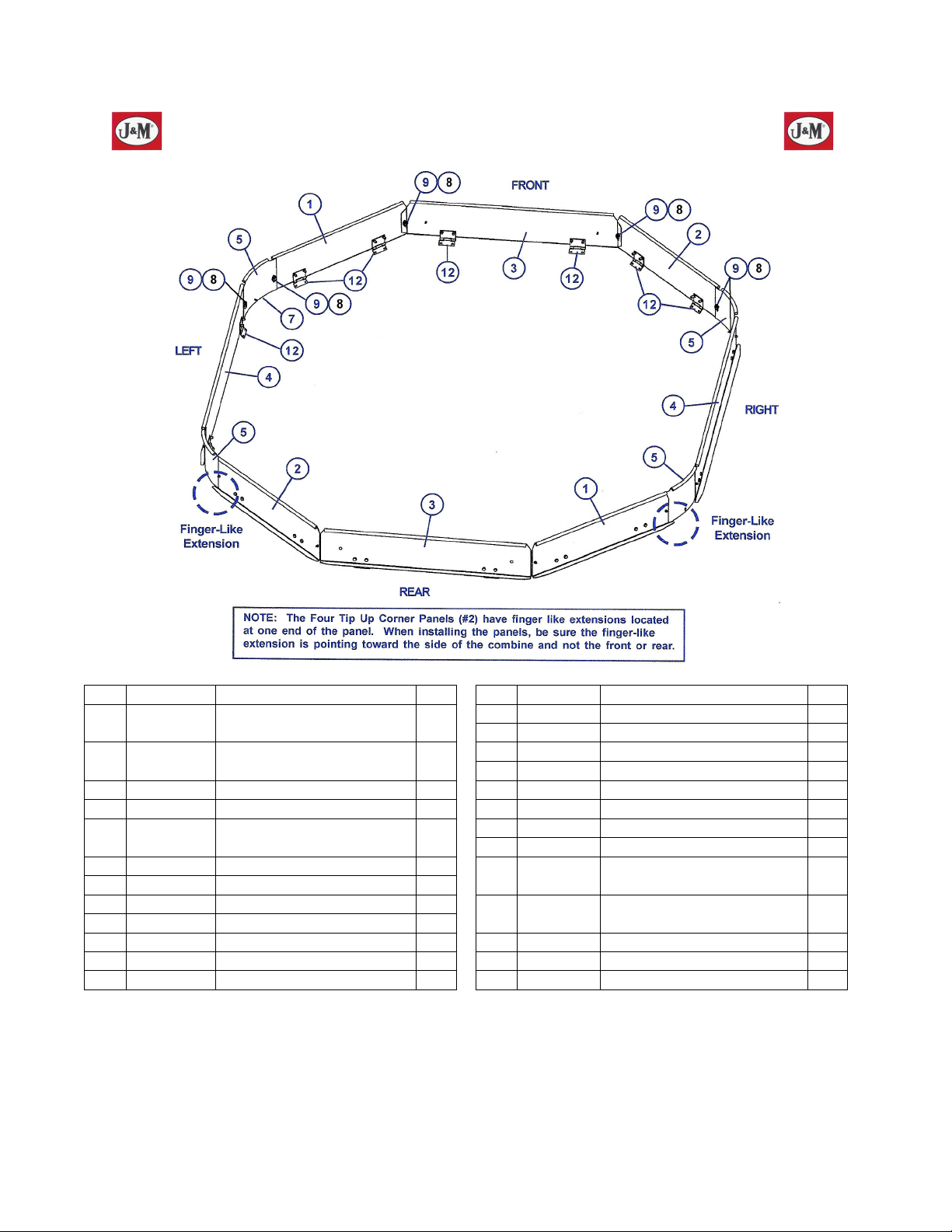
IMPORTANT: The four rounded tip up corner panels have a finger-like extension located at one
end. When installing the tip up corner panels, be sure the finger-like extension is pointing toward
the side of the combine and not toward the front or rear of the combine.
Secure the bottom half of the hinge to the existing corner
panel using two 5/16” x 5/8” bolt and 5/16” lock nuts. Drill
3/8” diameter holes in the existing corner panel lip at each of
the remaining hinge hole locations and bolt the hinge to the
existing corner panel using two 5/16” x 5/8” bolts and 5/16”
lock nuts. Repeat to install the remaining three corner
panels. Do not completely tighten the hinges to the existing
tank panels until after the front and rear tip up panels are
installed.
Step 2 Connect the front and rear tip up panels to the tabs
located on each end of the tip up corner panel and
secure using lynch pins. Center and adjust the
panels as necessary. Align the hinges on the front
and rear tip up panels with the top edge of the
existing tank panels. Drill 3/8” holes at each hinge
hole location and secure to the existing tank front
and rear panels using 5/16” x 5/8” bolts and 5/16”
lock nuts. Tighten all the bolts on the tip up panel
hinges.
Step 3 Attach the four rounded corner tip up panels to the
tabs on the ends of the corner tip up panels and
secure using lynch pins.
Page 4

SET-UP INSTRUCTIONS
Tip Up Kit for 2007 John Deere Combine 60 Series Factory Installed Extensions
Step 4 Connect the side tip up panels between the rounded corner tip up panels using the lynch pins
provided. Center and adjust the panels as necessary. Align the hinges on the front and rear tip
up panels with the top edge of the existing tank panels. Drill 3/8” holes at each hinge hole
location and secure to the existing tank side panels using 5/16” x 5/8” bolts and 5/16” lock nuts. If
necessary, apply rubber foam adhesive strip to the back side of the corner tip up panels to
eliminate any gaps between panels.
Step 5 Remove the existing combine baffle brace. Install the tank brace support using the existing bolts
from the baffle brace. Position the top end of the tank brace underneath the existing tank
extension frame. Slide the top portion of the brace up against the tank frame for additional
support and secure by tightening the 3/8” x 1” flange bolt and 3/8” flange nut.
Step 6 Place the sensor bracket on an appropriate tip up panel at the desired location. Mark and drill
3/8” holes and secure to the tip up panel using 5/16” x 5/8” bolts and 5/16” lock nuts. Relocate
and secure the sensor to the bracket.
 Loading...