

Page 1
O P E R A T O R ’ S M A N U A L
Set-Up Instructions and Parts Catalog for
Models 1384L and 1384S Running Gears
13 Ton Capacity
Optional Hydraulic Drum Brakes
J. & M. Manufacturing Co., Inc.
P.O. Box 547
Fort Recovery, OH 45846
Phone: (419) 375 2376 Fax: (419) 375-2708
E-mail: sales@jm-inc.com
Website: www.jm-inc.com
REV-03-18-10
Pg. 1
Page 2

TO THE DEALER:
Read manual instructions and safety rules. Make sure all items on the Dealer’s Pr e-Delivery and Delivery Check
Lists in the Operator’s Manual are completed before releasing equipment to the owner.
The dealer must complete the Warranty Registration Card attached to the front inside cov er of this manual and retu rn
to J. & M. Mfg. Co., Inc. at the address indicated on the card. Warranty claims wi ll be denied if the Warranty
Registration Card has not been completed and returned.
EXPRESS WARRANTY:
J. & M. Mfg. Co. Inc. warrants against defects in construction or materials for a period of ONE year. We reserve the
right to inspect and decide whether material or construction was faulty or whether abuse or accident voids our
guarantee.
Warranty service must be performed by a dealer or service c enter authorized by J. & M. Mfg. Co. Inc. to sell and/or
service the type of product involved, which will use onl y new or remanufactured p arts or components furnished b y J.
& M. Mfg. Co. Inc. Warranty service will be performed without charge to the purchaser for parts or labor based on th e
Warranty Labor Times schedule. Under no circumstance will allowable labor times extend beyond the maximum
hours indicated in the Warranty Labor Times schedule for each warranty procedure. The purchaser will be
responsible, however, for any service call and/or transportation of the product to and from the dealer or service
center’s place of business, for any premium charged for overtime labor requested by the purchaser, and for any
service and/or maintenance not directly related to any defect covere d under the warranty. Costs associated with
equipment rental, product down time, or product disposal are not warrantable a nd will not be accepted under any
circumstance.
Each warranty term begins on the date of product delivery t o the purchas er. Under no circumstance will warranty be
approved unless (i) the product warranty registration card ( attached to the inside of the Operator’s Manual) has been
properly completed and submitted to the equipment manufact urer. This Warranty is effective only if the warranty
registration card is returned within 30 days of purchase.
This warranty does not cover a component which fails, malfunctions or is damaged as a result of (i) improper
modification or repair, (ii) accident, abuse or improper use, (iii) improper or insufficient mainte nance, or (iv) normal
wear or tear. This warranty does not cover products that are previously owned and extends solely to the original
purchaser of the product. Should the original purchaser sell or other wise transfer this product to a third party, this
Warranty does not transfer to the third part y purchas er i n an y way. J. & M. Mfg. Co. Inc. makes no warranty, express
or implied, with respect to tires or other parts or accessories not manufactured by J. & M. Mfg. Co. Inc. Warranties
for these items, if any, are provided separately by their respective manufacturers.
THIS WARRANTY IS EXPRESSLY IN LIEU OF ALL OTHER WARRANTIES OR CONDITIONS, EXPRESS,
IMPLIED OR STATUTORY, INCLUDING ANY IMPLIED WARRANTY OF MERCHANTABILITY OR FITNESS FOR
PARTICULAR PURPOSE.
In no event shall J. & M. Mfg. Co. Inc. be liable for specia l, direct, incidental or consequential dam ages of any kind.
The exclusive remedy under this Warranty shall be repair or replacement of the defective component at J. & M. Mfg.
Co. Inc’s. option. This is the entire agreement between J. & M. Mfg. Co. Inc. and the Owner about warrant y and no J.
& M. Mfg. Co. Inc. employee or dealer is authorized to make any additional warranty on behalf of J. & M. Mfg. Co.
Inc.
The manufacturer reserves the right to make product design and material changes at any time without notice. They
shall not incur any obligation or liab ility to in corporate such changes and i mprovements in pr oducts previousl y sold to
any customer, nor shall they be obligated or liable for the replacement of previously sold products with products or
parts incorporating such changes.
SERVICE:
The equipment you have purchased has b een carefully manufactured to provide dependable and sat isfactory use.
Like all mechanical products, it will require cleaning and upk eep. Lubricate the unit as specified. Observe all s afety
information in this manual and safety signs on the equipment.
For service, your authorized J. & M. dealer has trained mec hanics, genuine J. & M. service parts, a nd the necessar y
tools and equipment to handle all your needs.
Use only genuine J. & M. service parts. Substitute parts may void the warranty and may not meet standards required
for safe and satisfactory operation. Record the model number and serial number of your equipment in the spaces
provided:
Serial # ___________ Purchase Date: _______ Purchased From: ________ ____________________________
Please provide this information to your dealer to obtain the correct parts:
Pg. 2
Page 3
MODEL 1384 - 13 TON RUNNING GEAR
Specifications
Capacity 13 Ton
Weight (with tires) 1,850 lbs.
Width (c/c of tires) 82”
Spindle Size 2 1/2” diameter (sleeved)
Spring Balance Tongue Standard
Ground Height (to top of axle) 26” (1384L); 31” (1384S)
Rocking Bolster Optional
Tongue, Adj. Quick Hitch Standard
Adjustable Center Pole Standard
Hydraulic Brake System Optional Two Wheel Drum
Wheels – 8 Bolt 22.5x8.25 or 22.5 x 13.5
GENERAL INFORMATION
TO THE OWNER:
The purpose of this manual is to assist you in operating and maintaining your running gear in a safe
manner. Read it carefully. It furnishes information and instructions that will help you achieve years of
dependable performance and help maintain safe operating conditions. If this machine is used by an
employee or is loaned or rented, make certain that the operator(s), prior to operating:
1. Is instructed in safe and proper use.
2. Reviews and understands the manual(s) pertaining to this machine.
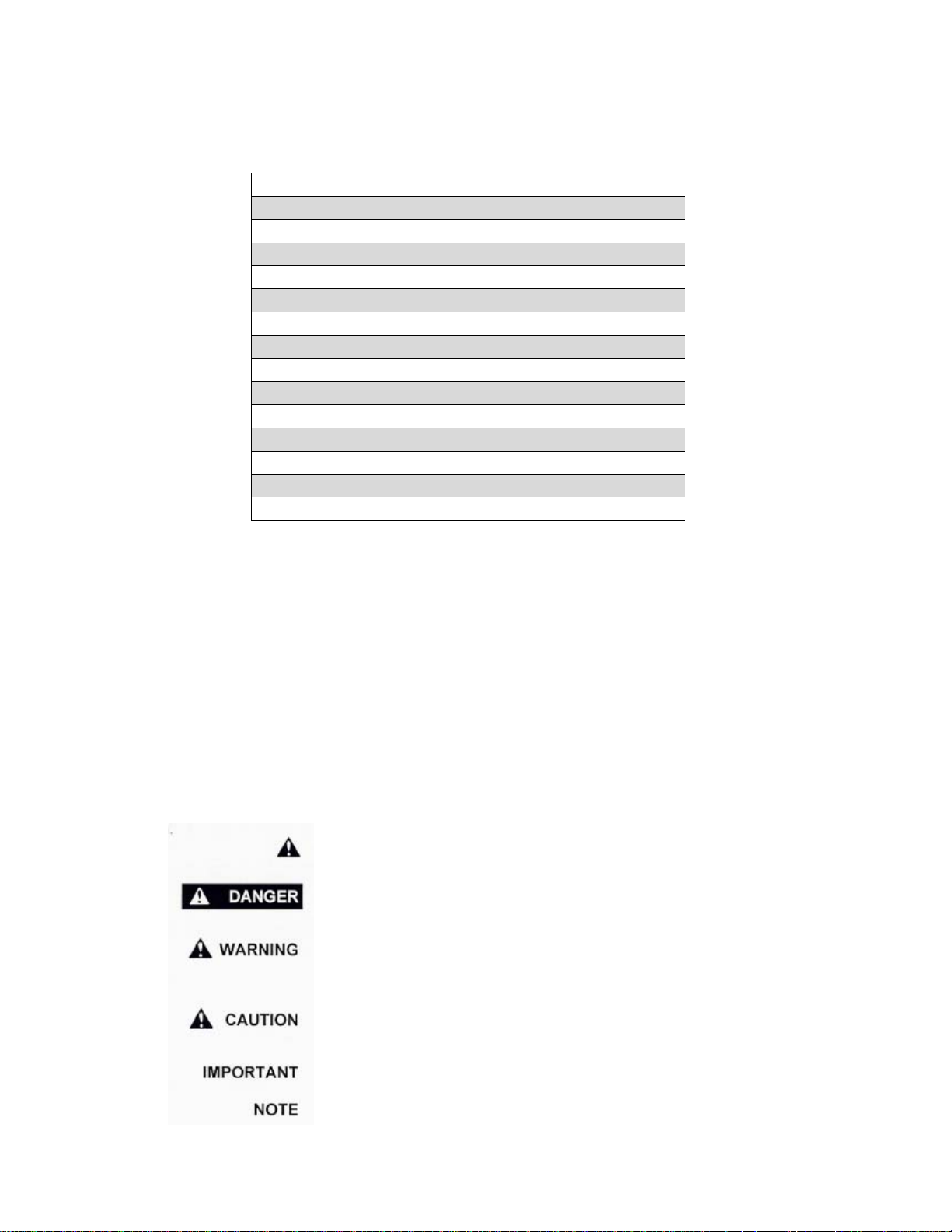
Throughout this manual, the term IMPORTANT is used to indicate that failure to observe can cause
damage to equipment. The terms CAUTION, WARNING and DANGER are used in conjunction with the
Safety-Alert Symbol, (a triangle with an exclamation mark), to indicate the degree of hazard for items of
personal safety. When you see this symbol, carefully read the message that follows and be alert to the
possibility of personal injury or death.
This Safety-Alert symbol indicates a hazard and means
ATTENTION! BECOME ALERT! YOUR SAFETY IS INVOLVED!
Indicates an imminently hazardous situation that, if not avoided, will
result in death or serious injury.
Indicates a potentially hazardous situation that, if not avoided, could
result in death or serious injury, and includes hazards that are exposed
when guards are removed.
Indicates a potentially hazardous situation that, if not avoided, may result
in minor or moderate injury.
Indicates that failure to observe can cause damage to equipment.
Indicates helpful information.
Pg. 3
Page 4
GENERAL INFORMATION (continued)
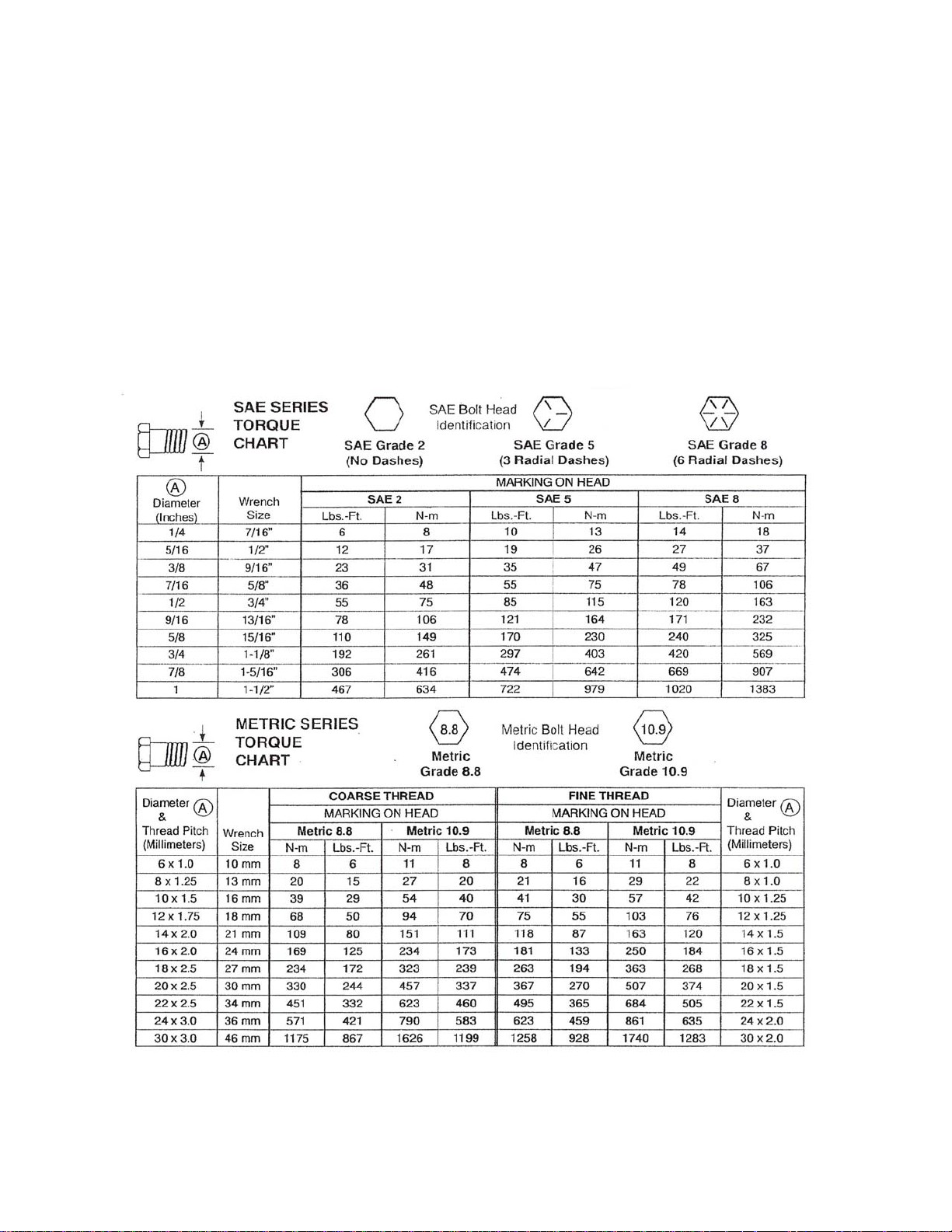
BOLT TORQUE CHART
Always tighten hardware to these values unless a different torque or tightening procedure is listed for a
specific application.
Fasteners must always be replaced with the same grade as specified in the manual parts list.
Always use the proper tool for tightening hardware. SAE for SAE hardware and Metric for metric
hardware.
Make sure fastener threads are clean and you start the thread engagement properly. All torque values
are given to specification used on hardware defined by SAE J1701 & J1701M (Jul 96).
Pg. 4
Page 5

TABLE OF CONTENTS
INTRODUCTION 2
EXPRESS WARRANTY 2
SPECIFICATIONS 3
GENERAL INFORMATION 3
BOLT TORQUE CHART 4
SAFETY RULES 6
SAFETY SIGNS 7
SET-UP INSTRUCTIONS 7-8
OPERATING INSTRUCTIONS 9
ROUTINE MAINTENANCE 9
PARTS LIST / DIAGRAM 10
OPTIONAL HYDRAULIC DRUM BRAKES 11 – 12
SERVICE RECORDS 13
Pg. 5
Page 6

SAFETY RULES
ATTENTION! BECOME ALERT! YOUR SAFETY IS INVOLVED!
Safety is a primary concern in the design and manufacture of our products. Unfortunately, our efforts to
provide safe equipment can be erased by an operator’s single careless act. In addition, hazard control
and accident prevention are dependent upon the awareness, concern, judgment, and proper training of
personnel involved in the operation, transport, maintenance and storage of equi pment.
Make certain that the operator(s), prior to operating is instructed in safe and proper use and reviews and
understands the manual(s) pertaining to this machine.
Read this manual before you operate this machine. If you do not understand any part of this manual, or
need more information, contact the manufacturer or your authorized dealer.
SAFETY
Understand that your safety and the safety of other persons are measured by how you service, and
operate this machine. Know the positions and functions of all controls before you try to operate them.
Make sure to check all controls in a safe area before starting your work.
The safety information given in this manual does not replace safety codes, federal, state or local laws.
Make certain your machine has the proper equipment as designated by local laws and regulations.
A frequent cause of personal injury or death is from persons falling off equipment and being run over. Do
not permit persons to ride on this machine.
Travel speeds should be such that complete control and machine stability is maintained at all times.
Where possible, avoid operating near ditches, embankments and holes. Reduce speed when turning,
crossing slopes and rough, slick or muddy surfaces.
Collision of high speed road traffic and slow moving machines can cause personal injury or death. On
roads, use flasher lights according to local laws. Keep slow-moving-vehicle emblem visible. Pull over to
let faster traffic pass.
Never adjust, service, clean, or lubricate running gear until all power is shut off.
Keep all safety shields in place.
Keep hands, feet, hair and clothing away from moving parts while unit is in operation.
Make sure that everyone is clear of equipment before applying power or moving the machine.
Make sure that the implement is fastened securely to the tractor by using the proper hitch pin, clip and
safety chains.
Never overload the running gear. Overloading the running gear is dangerous and can cause extensive
damage.
Do NOT exceed speeds in excess of 20 MPH. Rim, hubs and bearings are designed for heavy loads at
slow speeds. Also be sure slow moving vehicle emblem is attached to rear of wagon.
Before unhooking the implement from the towing unit, be sure to properly block the wheels to prevent the
implement from moving.
Pg. 6
Page 7

SAFETY SIGNS
IMPORTANT: Install new safety signs if the old signs are destroyed, lost, painted over or cannot be read.
When parts are replaced that have safety signs, make sure you install a new sign with each new part.
New signs are available from the manufacturer or your authorized dealer.
DECAL PARTS LIST
Item # Part # Description
1 DC-111 Caution: Keep Lug Nuts Tight
2 DC-113 Caution: Check Fluid Level
3 DI-114M J&M Oval - Medium
SET-UP INSTRUCTIONS
IMPORTANT: Set-up work to be performed by qualified servicemen only.
1. Mount tires on the wheels and inflate per tire manufacturer’s recommendations and instructions. When
using 22.5x8 ¼ wheels, mount the wheel with the offset inward, valve stem outward. This will make the
tread width 82” (center of wheel to center of wheel) and allow clearance between tire and the frame when
turning.
2. Mount the tires to the hubs and tighten the tapered hub nuts to 100 ft. lb. torque or the flat hub nuts to
100 ft. lb. torque . Check the hub nuts after the first hour of operation, then every 10 hours of operation
for the first 40 hours of use. These nuts must be kept tight at all times. Wheels that are improperly
installed on the running gear, resulting in product failure, will nullify the warranty and shift the burden of
liability to the owner/operator of the equipment.
3. Slide the coupling pole into the front and back assemblies, slipping the collar in the back assembly.
When mounting to a 385SD Gravity Wagon, the spacing on the coupling pole (approximate distance
between holes on the coupling pole) should be 24” (Measured between the closest two bolts). The
distance from the center of axle to center of axle is approximately 104”.
4. Fasten the tongue to the front of the assembly using the tongue bolt and hex nuts. Attach the tongue
springs to the brackets on the tongue and hitch assembly. Check underneath the tongue and make sure
the 7/8” x 2 ¼” bolt with spacer is secure.
5. Mounting Brake Lines to Running Gear with Hydraulic Drum Brakes. IMPORTANT: Running Gears
with Hydraulic Brakes should be set up immediately after delivery from factory to prevent dirt and
moisture from entering the brake system. Mount the brakes lines from the rear of the master cylinder to
the Drum Brakes according to the Tongue Assembly and Brake Lines and Fittings drawing located in the
Repair Parts Section of this manual. Be careful not to over tighten the fittings and strip the threads. Use
care in shaping brake lines to avoid sharp bends or kinks. Be sure to use a “Double-Flaring” type of tool
on steel tubing to assure tight leak proof connections. Be sure and use hydraulic rubber hoses at points
of flexing. Anchor hose ends to avoid stress on tubing. Always use DOT 5 Silicone Brake Fluid or
equivalent.
Pg. 7
Page 8

SET-UP INSTRUCTIONS (continued)
IMPORTANT: Set-up work to be performed by qualified servicemen only.
6. Adding Brake Fluid to the Master Cylinder. IMPORTANT: Do NOT shake the brake fluid container.
AVOID agitating the system when bleeding. Do NOT “pump” the brake plunger. Instead, depress and
release slowly.
Fill the master cylinder carefully, pouring the fluid down the side of the reservoir to minimize air
entrainment.
METHOD ONE (requires two people)
Close all bleed screws.
Start with the wheel furthest from the master cylinder. Slip a transparent bleed hose on the bleeder stem
and place the other end of the hose in a clean container which is partially filled with fluid at all times.
The first person depresses the brake plunger SLOWLY (take 3-5 seconds). THEN the second person
opens the bleed screw. He then closes the bleed screw BEFORE the first person SLOWLY releases the
plunger (3-5 seconds). Continue until there is no evidence of air in the bleed hose. Continue with
remaining wheels working from the longest to the shortest distance from the master cylinder. Top off
master cylinder as needed to prevent reintroducing air into the lines.
REMEMBER:
1) Depress plunger slowly
2) Open bleed screw
3) Close bleed screw
4) Release plunger slowly
METHOD TWO (one person)
Attach bleed hose to rear wheel as in method one. Open bleed screw. SLOWLY depress plunger (3-5
seconds). Repeat until line is air free. Close bleed screw. Top off master cylinder as needed to prevent
reintroducing air into the lines.
Repeat with remaining wheel.
Contamination with dirt, water, petroleum products or other materials may result in brake failure or costly
repairs.
7. IMPORTANT: Make sure to properly attach the gravity box (or other equipment) to the running gear.
Bolt all four corners of the gravity box to the running gear. If the box is used in rough terrain and it is not
equipped with a rocking bolster, bolt a minimum of two corners and chain (or cable) the remaining two
corners to allow more box flexibility.
MOUNTING WHEELS
The adjacent diagram shows the proper way to mount wheels with straight holes (22.5x13.5 wheels).
Use flange wheel nut (valve stem is on the outward side of the tire). Wheels that are improperly installed
on running gears, resulting in product failure, will nullify warranty and shift the burden of liability to the
owner/operator of the equipment.
Pg. 8
Page 9

OPERATION INSTRUCTIONS / /MAINTENANCE
WARNING - BE CERTAIN THAT ALL POWER IS SHUT OFF BEFORE SERVICING EQUIPMENT.
Before equipment is put into service:
Has this manual and the operator’s manual of the gravity box been read and clearly understood by the
operator(s) of this machine?
Have all braces, bolts, nuts, lug bolts and lug nuts been checked to ensure that they are properly
fastened?
Is the running gear properly fastened to the tractor? Use a good quality hitch pin with clip and safety
chains.
SAFEY CHAIN USER INSTRUCTIONS
a) Secure the safety chain by looping it around the tongue support located on the underside of
the outer tongue. Extend the chain through the support located on the underside of the inner
tongue and connect to the towing machine’s attaching bar.
b) Be sure to run the safety chain through the support on the underside of the inner tongue. This
will provide an intermediate support for the safety chain.
c) Do NOT allow more slack than necessary for articulation (max. 9 inches).
d) Do NOT use any intermediate support as the attaching point.
e) Store the safety chain by securing it around the tongue supports.
f) Replace the safety chain if one or more links or end fittings are broken, stretched or otherwise
damaged or deformed.
Have all danger, warning, caution and important signs on the equipment been read and clearly
understood? If employees or others use or are near this equipment, make sure they also have read and
understood all danger, warning, caution and important signs on the equipment and have also read the
operator’s manual.
Have the wheel bearings been inspected? Repack with grease if needed. Grease both the tongue bolt
and the hitch bolt.
BRAKING SYSTEM REQUIREMENTS:
WARNING - Tow Loads Safely
Stopping distance increases with speed and weight of towed loads, and on slopes. Towed loads with or
without brakes that are too heavy for the tractor or are too fast can cause loss of control. Consider the
total weight of the equipment and its load.
Observe these recommended maximum road speed, or local speed limits which may be slower:
• If towed equipment DOES NOT have brakes, do not travel more than 32 km/hr (20 mph) and
do not tow loads more than 1.5 times the tractor weight.
• If towed equipment DOES have brakes, do not travel more than 40 km/hr (25 mph) and do
not tow loads more than 4.5 times the tractor weight.
•
Ensure the load does not exceed the recommended weight ratio. Use additional caution when towing
loads under adverse conditions, when turning and on inclines.
Pg. 9
Page 10

OPERATION INSTRUCTIONS / /MAINTENANCE (continued)
IMPORTANT:
Keep the tires properly inflated (approx. 80 psi). Both under and over inflation can greatly reduce tire life.
Inspect bracing and welds and repair if needed. Failure to repair could cause extensive damage and
greatly reduce the life of the unit.
Inspect tie rods and replace the bronze bushings in the steering assembly when needed.
Repack the bearings in the hub assemblies once a year or as needed. Use a good quality bearing
lubricant such as Bearing Gard MK1 or equivalent. NOTE: Grease zerks on hubs caps are for between
scheduled service lubrication.
If equipped with brakes, inspect the drums periodically for wear and for brake line damage. Check fluid in
the master cylinder and inspect for dirt or corrosion on the inside wall of the master cylinder. Clea n and
replace with new Silicone Brake Fluid (DOT 5) if needed. Wagons with brakes should be stores in a
clean, dry place when not in use.
ADJUSTING THE DRUM BRAKES
IMPORTANT: When adjusting drum brakes, rotate the wheel and drum in a forward
The brake adjustment nut is located behind a slot at the bottom of the backing plate. Tighten the nut until
you cannot rotate the wheel by hand, then back off the adjustment 18 to 20 notches.
rotation only.
Pg. 10
Page 11

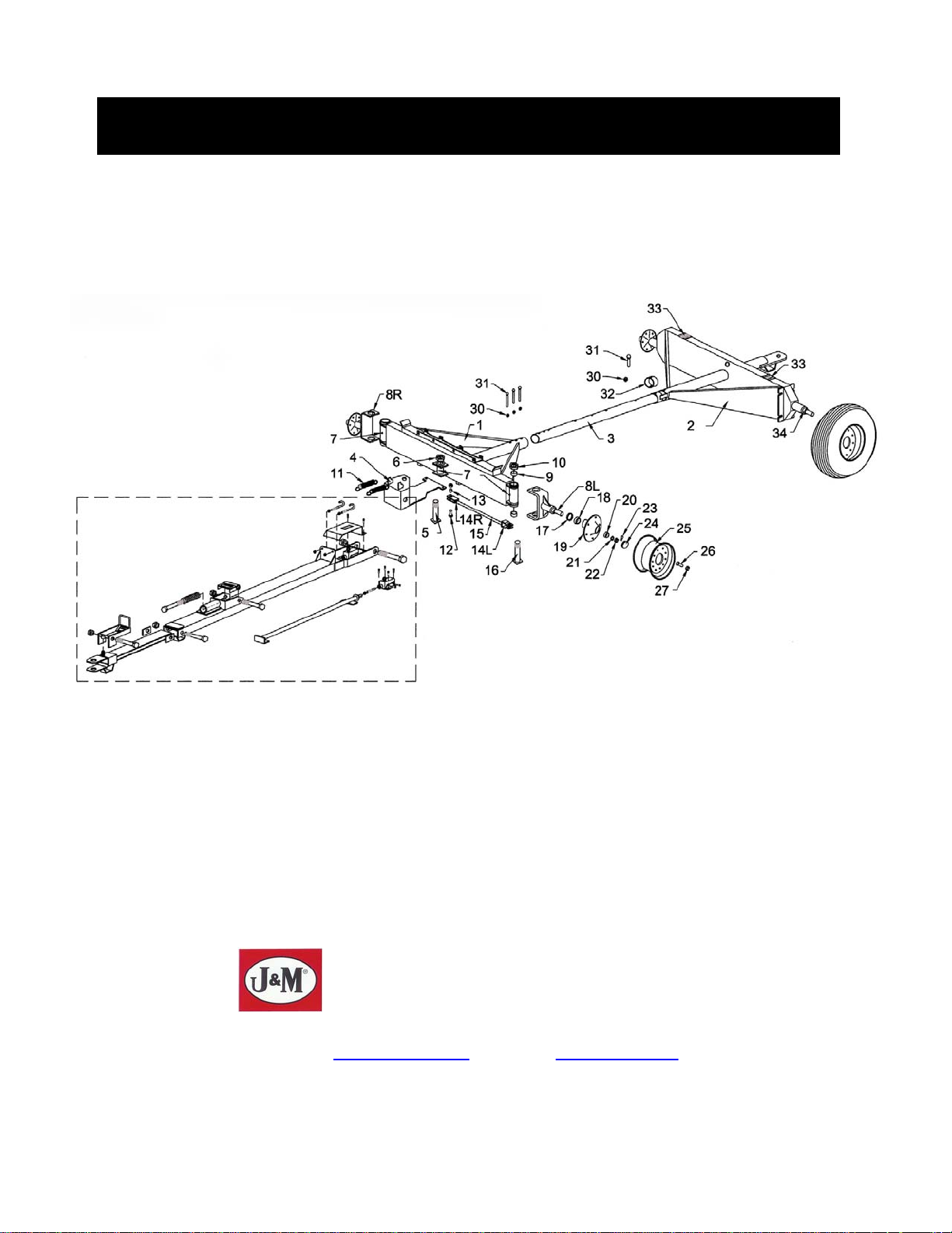
MODEL 1384 RUNNING GEAR REPAIR PARTS LIST
# Part # Description Qty # Part # Description Qty
1 OT-1215NS Adj. Tongue Outer Weldment 1 23 RS-13 Rear Spindle 1
2 IT-1215NS Adj. Tongue Inner Weldment 1 24 MB-346 3/4" x 6” Bolt 2
3 TL-1215NS Tongue Latch Weldment 1 25 LN-34 3/4" Lock Nut 2
4 SS-615NS Small Spring in Latch 1 26 TS-615 Large Tongue Spring 1
5 LS-1215 Latch Pivot Shaft, 1” Diameter 1 27 CP-4 Coupling Pole 1
6 CP-112 Cotter Pin 2 28 ST-1215 Standards (optional) 4
7 TT-13 Telescoping Tongue Complete 1 29 MB-126 1/2" x 5 1/2" Bolt 8
8 TB-1215 Tongue Pivot Bolt 1 30 HN-12 1/2" Lock Nut 8
9 HN-114 Regular Hex Nut 4 31 CL-412 Collar to Coupling Pole 1
10 KP-1215 King Pin Bolt 1 32 H-812-1 Hub Incl. Lug Bolt & Nuts 4
11 HW-1215 Hitch Weldment 1 33
12 BB-34 Bronze Bushing, 3/4” 4 34 3780 Inner Bearing (Large) 4
13 SB-34 Special Step Bolt, 3/4" 4 35 2790 Outer Bearing (Small) 4
14L TRE-1L Tie Rod End, Left 2 36 SW-1314-78 Spindle Washer 4
14R TRE-1R Tie Rod End, Right 2 37 SN-1-78 Slotted Spindle Nut 4
15L HN-1L 1”-14 Hex Nut, Left 2 38 CP-316 Cotter Pin 4
15R HN-1R 1”-14 Hex Nut, Right 2 39 DC-17 Dust Cap 4
16 TR-20 Tie Rod, 1” Diameter 2 40 WR-16114 Wheel Rim, 8 Hole, 16.1 x 14 4
17L SA-13L Spindle and U-Assy w/Arm, L/H 1 40 WR-225-825 Wheel Rim, 8 Hole, 22.5 x 8.25 4
17L SA-13L-S* Spindle and U-Assy w/Arm, L/H 1 40 WR-225-135 Wheel Rim, 8 Hole, 22.5 x 13.5 4
17R SA-13R Spindle and U-Assy w/Arm, R/H 1 41 WB-41 Wheel Stud 32
17R SA-13R-S* Spindle and U-Assy w/Arm, R/H 1 42 WB-40 Wheel Nut 32
18 EB-134 End Spindle Bronze Bushing 4 43 1633 Grease Fitting 4
19 SPN-134 Spindle Bolt x 13 1/2" 2 44 SB-212 Spacer Blocks 2
20 HN-134 1 3/4" Hex Nut 2 45 78214-BS 7/8” x 2 1/4” Bolt with Spacer 1
21 FA-1215 Front Axle Weldment 1 46 3720 Inner Cup, Large 4
22 RA-13 Rear Axle Weldment 1 47 2720 Outer Cup, Small 4
22 RA-13-SC* Rear Axle Weldment 1
* For Standard Clearance Running Gears
SE-17-25091
Grease Seal 4
Pg. 11
Page 12

MODEL 1384 RUNNING GEAR REPAIR PARTS LIST FOR HYDRAULIC DRUM BRAKES
Tongue Assembly and Brake Lines and Fittings
PARTS LIST
# Part # Description # Part # Description
1 OTW-1324 Outer Tongue Weldment 21 PRE-1 Plunger Rod End
2 ITW-1324 Inner Tongue Weldment 22 MBMC-DR2 Mounting Bracket (2 pcs) (M/C)
3 TL-1324 Tongue Latch 23 38-FN 3/8” Flange Nut
4 SS-615NS Small Spring In Latch 24 38-LN 3/8” Lock Nut
5 17G2B 1” x 7” Grade 2 Bolt 25 PP-1D Plunger Pole
6 1LN 1” Lock Nut 26 RB-1415 Rubber Boot on M/Cylinder
7 BL-58 Brake Limiter 27 GR-1415 Rubber Grommet
8 19G8B 1” x 9” Grade 8 Bolt 28 SKMC-1324 Seal Kit for Master Cylinder
9 CS-178714 Compression Spring 29 DOT5-BF Container DOT 5 Brake Fluid
10 1RN 1” Regular Nut 30 WB-41L Wheel Stud (Long Knurl)
11 TB-1315 Tongue Bolt 31 H-812-1B Hub, Faced for Brakes
12 HN-114 1 1/4” Hex Nut 32 BS-24 Bleeder Stem
13 SMC-1 Shield for Master Cylinder 33 HH-1424 1/4” x 24” Hydraulic Hose
14 124-JB 1/2” x 4” J-Bolt 35 ST-96 3/16” Brake L ine x 96”
15 12-N 1/2” Regular Nut 36 ST-53 3/16” Brake Line x 53”
16 381-FB 3/8” x 1” Flange Bolt 37 10606 Tee
17 FMC-015 Fitting for Master Cylinder 38 SC-1324 Spring Clip
18 MCA-DR1 Master Cylinder Assembly
19 RMCM-1324 Replacement Cap (M/Cylinder)
20 383G8B 3/8” x 3” Grade 8 Bolt
Pg. 12
Page 13

MODEL 1384 RUNNING GEAR REPAIR PARTS LIST FOR HYDRAULIC DRUM BRAKES
Drum Brake Assembly
PARTS LIST
# Part # Description # Part # Description
1 24737 Back Plate Assembly 21 17406 Hex – Locknut 5/16” NC
2 9739 Front Brake Shoe Assembly 28 9743 Travel Link
3 9745 Front Shoe Lever 29 7949 Travel Link Bolt – Hex Cap
4 9775 Rear Shoe Lever
5 9776 Wheel Cylinder Assembly – Right 30 12560 Front Shoe Pin w/o Park Link
6 9777 Wheel Cylinder Assembly – Left 31 6814 Spring – Front Shoe
7 23457 Screw & Lockwasher 32 9797 Plug – Plastic
8 23324 Adjusting Screw 33 7972 Hex Nut 1/2” NF
9 23324PN Pivot Nut 34 7955 Cap Screw 1/2” NF x 1”
10 9782 Socket – Adjusting Screw 35 7937 Lockwasher 1/2”
11 9783 Push Rod – Wheel Cylinder 36 9404 Plug – Plastic
12 9784 Spring Adjusting Screw (Yellow) 39 15845 Wheel Cylinder Repair Kit 1 1/8”
13 9785 Spring – Front Lever (Red) 40 DRBA-L Drum Brake Cluster Assy (left)
14 9786 Spring – Rear Shoe (Orange) 40 DRBA-R Drum Brake Cluster Assy (right)
15 9788 Pin – Shoe Hold Down 41 1314BD 13” Brake Drum (5 3/4” pilot)
16 9789 Cup – Shoe H old Down
17 9790 Spring – Front Hold Down (Yellow)
18 9791 Spring – Rear Hold Down (Black)
19 9254 Cover Plate – Adjusting Hole
20 7778 Retaining Ring
Screw 5/16” NC x 5/8”
Pg. 13
Page 14

SERVICE / MAINTENANCE RECORD
Date Description Notes
Pg. 14
 Loading...