

Page 1

OPERATOR’S MANUAL
PATENTED SINGLE AUGER
GRAIN CARTS
1050-18S Grain Cart
JMMAN0101 (Rev . 03/14/06)
J. & M. Mfg. Co., Inc.
P.O. Box 547 Ft. Recovery, OH 45846
Ph: (419) 375-2376 Fax: (419) 375-2708
www.jm-inc.com
Page 2

TO THE DEALER:
Read manual instructions and safety rules. Make sure all items on the Dealer’s Pre-Delivery and Delivery Check Lists
in the Operator’s Manual are completed before releasing equipment to the owner.
The dealer must complete the Warranty Registration Card attached to the front inside cover of this manual and return
to J. & M. Mfg. Co., Inc. at the address indicated on the card. Warranty claims will be denied if the Warranty
Registration Card has not been completed and returned.
EXPRESS WARRANTY :
J. & M. Mfg. Co. Inc. warrants against defects in construction or materials for a period of ONE year . We reserve the right
to inspect and decide whether material or construction was faulty or whether abuse or accident voids our guarantee.
Warranty service must be performed by a dealer or service center authorized by J. & M. Mfg. Co. Inc. to sell and/or
service the type of product involved, which will use only new or remanufactured parts or components furnished by J.
& M. Mfg. Co. Inc. Warranty service will be performed without charge to the purchaser for parts or labor based on the
Warranty Labor Times schedule. Under no circumstance will allowable labor times extend beyond the maximum
hours indicated in the Warranty Labor Times schedule for each warranty procedure. The purchaser will be responsible,
however, for any service call and/or transportation of the product to and from the dealer or service center ’s place of
business, for any premium charged for overtime labor requested by the purchaser, and for any service and/or
maintenance not directly related to any defect covered under the warranty. Costs associated with equipment rental,
product down time, or product disposal are not warrantable and will not be accepted under any circumstance.
Each warranty term begins on the date of product delivery to the purchaser. Under no circumstance will warranty be
approved unless (i) the product warranty registration card (attached to the inside of the Operator’s Manual) has been
properly completed and submitted to the equipment manufacturer, and (ii) a warranty authorization number has been
issued by the equipment manufacturer. This Warranty is effective only if the warranty registration card is returned
within 30 days of purchase.
This warranty does not cover a component which fails, malfunctions or is damaged as a result of (i) improper
modification or repair, (ii) accident, abuse or improper use, (iii) improper or insufficient maintenance, or (iv) normal
wear or tear. This warranty does not cover products that are previously owned and extends solely to the original
purchaser of the product. Should the original purchaser sell or otherwise transfer this product to a third party, this
Warranty does not transfer to the third party purchaser in any way. J. & M. Mfg. Co. Inc. makes no warranty , express or
implied, with respect to tires or other parts or accessories not manufactured by J. & M. Mfg. Co. Inc. Warranties for
these items, if any, are provided separately by their respective manufacturers.
THIS WARRANTY IS EXPRESSL Y IN LIEU OF ALL OTHER W ARRANTIES OR CONDITIONS, EXPRESS, IMPLIED OR
STATUTORY, INCLUDING ANY IMPLIED WARRANTY OF MERCHANTABILITY OR FITNESS FOR PARTICULAR
PURPOSE.
In no event shall J. & M. Mfg. Co. Inc. be liable for special, direct, incidental or consequential damages of any kind. The
exclusive remedy under this Warranty shall be repair or replacement of the defective component at J. & M. Mfg. Co.
Inc’s. option. This is the entire agreement between J. & M. Mfg. Co. Inc. and the Owner about warranty and no J. & M.
Mfg. Co. Inc. employee or dealer is authorized to make any additional warranty on behalf of J. & M. Mfg. Co. Inc.
The manufacturer reserves the right to make product design and material changes at any time without notice. They
shall not incur any obligation or liability to incorporate such changes and improvements in products previously sold to
any customer, nor shall they be obligated or liable for the replacement of previously sold products with products or
parts incorporating such changes.
SERVICE:
The equipment you have purchased has been carefully manufactured to provide dependable and satisfactory use.
Like all mechanical products, it will require cleaning and upkeep. Lubricate the unit as specified. Observe all safety
information in this manual and safety signs on the equipment.
For service, your authorized J. & M. dealer has trained mechanics, genuine J. & M. service parts, and the necessary
tools and equipment to handle all your needs.
Use only genuine J. & M. service parts. Substitute parts may void the warranty and may not meet standards required
for safe and satisfactory operation. Record the model number and serial number of your equipment in the spaces
provided:
Serial No.: Date of Purchase:
Purchased From:
Provide this information to your dealer to obtain correct repair parts.
2
Page 3
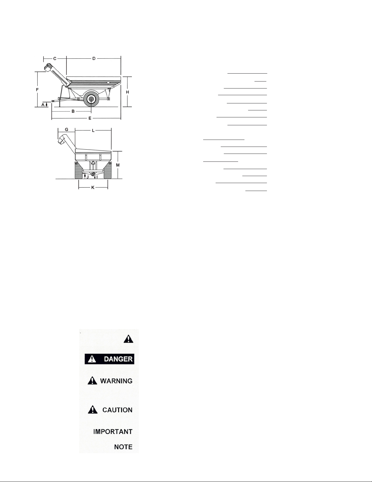
1050-18S GRAIN CART
SPECIFICATIONS
DIMENSIONS
A) 1’-9”
B) 18’-10”
C) 8’-6”
D) 22’-0”
E) 29’-7”
F) 13’-6”
G) 6’-4”
H) 12’-0”
I) 1’-2”
J) 2’-3”
K) 9’-6”/10’-0”
L) 11’-9”
M) 10’-11”
Note: Specifications are subject to change without notice or obligation
* Bushel capacities measured with #2 corn at 15% moisture (56 lb test wt.)
**Time varies with rpm and moisture content of grain
SPECIFICA TIONS
Capacity 1050 bushels
Auger, one vertical 18” diameter
Wheels 31x32 or 32x36
Hubs 10 bolt
Spindles 6” diameter
Weight (approx.) 13,100#
PT O 1,000 rpm
Tire Size 35.5x32, 20 ply or
73x44:00, 16 ply
Tongue Weight:
Empty 2,900 lbs
Loaded 4,200 lbs
Construction:
Hopper 12 GA Steel
Undercarriage 8” x 4” x 1/2” Tubing
Axle 7” x 7” x 1/2” Tubing
Unloading Time** 2.4 minutes (approx.)
GENERAL INFORMATION
TO THE OWNER:
The purpose of this manual is to assist you in operating and maintaining your grain cart in a safe manner . Read
it carefully . It furnishes information and instructions that will help you achieve years of dependable performance
and help maintain safe operating conditions. If this machine is used by an employee or is loaned or rented,
make certain that the operator(s), prior to operating:
1. Is instructed in safe and proper use.
2. Reviews and understands the manual(s) pertaining to this machine.
Throughout this manual, the term IMPORT ANT is used to indicate that failure to observe can cause damage to
equipment. The terms CAUTION, WARNING and DANGER are used in conjunction with the Safety-Alert
Symbol, (a triangle with an exclamation mark), to indicate the degree of hazard for items of personal safety .
When you see this symbol, carefully read the message that follows and be alert to the possibility of personal
injury or death.
This Safety-Alert symbol indicates a hazard and means
A TTENTION! BECOME ALER T! YOUR SAFETY IS INVOL VED!
Indicates an imminently hazardous situation that, if not avoided, will
result in death or serious injury .
Indicates a potentially hazardous situation that, if not avoided, could
result in death or serious injury , and includes hazards that are
exposed when guards are removed.
Indicates a potentially hazardous situation that, if not avoided, may
result in minor or moderate injury .
Indicates that failure to observe can cause damage to equipment.
Indicates helpful information.
3
Page 4
GENERAL INFORMATION
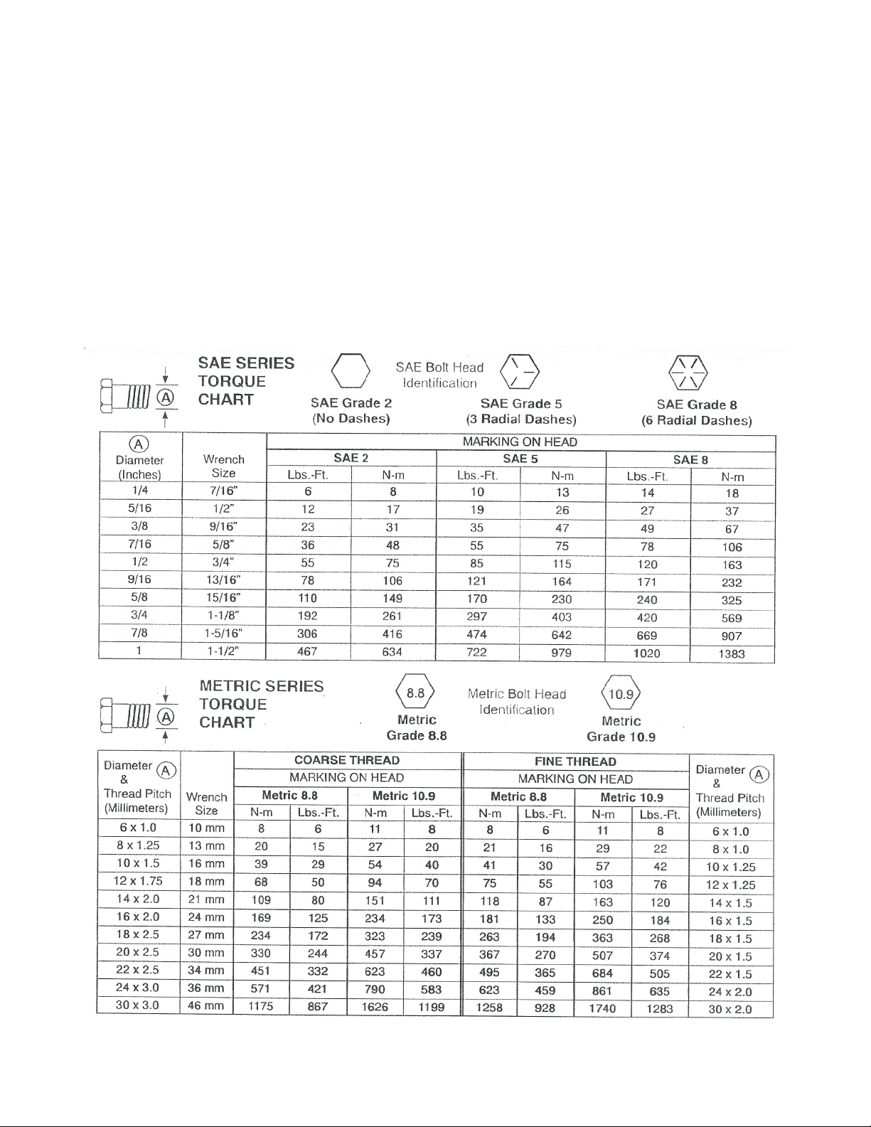
BOLT TORQUE CHART
Always tighten hardware to these values unless a different torque or tightening procedure is listed for a specific
application.
Fasteners must always be replaced with the same grade as specified in the manual parts list.
Always use the proper tool for tightening hardware: SAE for SAE hardware and Metric for metric hardware.
Make sure fastener threads are clean and you start thread engagement properly .
All torque values are given to specifications used on hardware defined by SAE J1701 & J1701M JUL 96.
4
Page 5

TABLE OF CONTENTS
INTRODUCTION 2
EXPRESS WARRANTY 2
SPECIFICATIONS 3
GENERAL INFORMA TION 3
BOLT TORQUE CHART 4
SAFETY RULES 6
SAFETY SIGNS 7
INITIAL OPERA TION 8
OPERATION 9-1 1
ROUTINE MAINTENANCE 1 1
TROUBLE SHOOTING 12
SERVICE 13-1 4
STORAGE 14
REMOVING FROM STORAGE 14
P ARTS LISTS/DIAGRAMS 1 5-2 0
WEIGH SCALE INSTALLA TION INSTRUCTIONS 21-23
ROLL T ARP INSTALLA TION 24-2 7
SERVICE RECORDS 28
5
Page 6

SAFETY RULES
A TTENTION! BECOME ALERT! YOUR SAFETY IS INVOL VED!
Safety is a primary concern in the design and manufacture of our products. Unfortunately , our efforts to provide
safe equipment can be erased by an operator’s single careless act. In addition, hazard control and accident
prevention are dependent upon the awareness, concern, judgement, and proper training of personnel involved in
the operation, transport, maintenance and storage of equipment.
Make certain that the operator(s), prior to operating is instructed in safe and proper use and reviews and
understands the manual(s) pertaining to this machine. Also make certain that the operator(s) reviews and
understands the operator’s manual of the tractor prior to hooking up or operating the grain cart.
Read this manual before you operate this machine. If you do not understand any part of this manual, or need
more information, contact the manufacturer or your authorized dealer .
SAFETY
Understand that your safety and the safety of other persons is measured by how you service, and operate this
machine. Know the positions and functions of all controls before you try to operate them. Make sure to check
all controls in a safe area before starting your work.
The safety information given in this manual does not replace safety codes, federal, state or local laws. Make
certain your machine has the proper equipment as designated by local laws and regulations.
A frequent cause of personal injury or death is from persons falling of f equipment and being run over. Do not
permit persons to ride on this machine.
Travel speeds should be such that complete control and machine stability is maintained at all times. Where
possible, avoid operating near ditches, embankments and holes. Reduce speed when turning, crossing slopes
and rough, slick or muddy surfaces.
Collision of high speed road traffic and slow moving machines can cause personal injury or death. On roads,
use flasher lights according to local laws. Keep slow-moving-vehicle emblem visible. Pull over to let faster
traffic pass.
Hydraulic oil leaking under pressure can penetrate skin and cause infection or other injury .
T o Prevent Personal Injury:
Relieve all pressure, before disconnecting fluid lines.
Before applying pressure, make sure all connections are tight and components are in good condition.
Never use your hand to check for suspected leaks under pressure. Use a piece of cardboard or
wood for this purpose.
If injured by leaking fluid, see you doctor immediately .
When transporting the grain cart, always keep the auger in stow position.
Use care when moving or operating grain cart near electric lines as serious injury or death can result from
contact.
Never adjust, service, clean, or lubricate grain cart until all power is shut off. Keep all safety shields in place.
Keep hands, feet, hair and clothing away from moving parts while unit is in operation.
The service ladder is for service work only . If you must climb into grain tank, be certain that all power is shut off
and then use extreme caution when climbing into grain cart.
Make sure that everyone is clear of equipment before applying power or moving the machine.
Make sure that the grain cart is fastened securely to the tractor by using a high strength hitch pin, clip and
safety chains. Make sure that the grain cart hitch properly matches the hitch type of the tractor. Use a single
prong (spade) grain cart hitch with a double prong (clevis) tractor hitch. Use a double prong (clevis) grain cart
hitch with a single prong (spade) tractor hitch.
Before filling the grain cart, make certain that no one is inside the grain tank. Never allow children or anyone in,
near, or on the grain cart during transport or during loading and unloading of grain. Be aware that moving grain
is dangerous and can cause entrapment, resulting in severe injury or death by suffocation.
Never operate the auger system with anyone inside of the grain tank. Hands, feet, hair, and clothing can fit
through the openings in and around the grate. Contact with the auger can cause severe injury or death. Make
certain that all power is shut off before service work is performed.
Before unhooking the grain cart from the tractor, be sure to properly block the wheels to prevent the cart from
moving.
6
Page 7
750-16 OWNER’S MANUAL
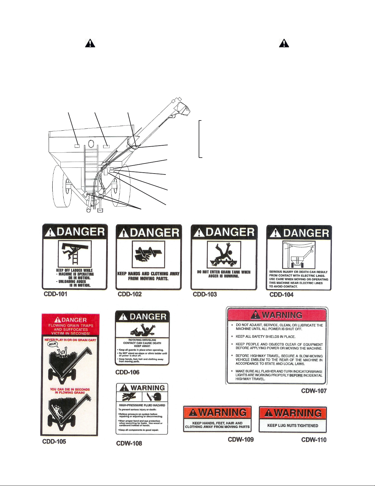
SAFETY SIGNS
A TTENTION! BECOME ALERT! YOUR SAFETY IS INVOL VED!
Replace Immediately If Damaged or Missing!
IMPORTANT: Install new safety signs if the old signs are
destroyed, lost, painted over or cannot be read. When
parts are replaced that have safety signs, make sure you
install a new sign with each new part. New signs are
available from the manufacturer or your authorized dealer.
31 7
Not
Shown
2
4
17
5
Ref. # Description Part #
1 Sign, Danger CDD-101
2 Sign, Danger CDD-103
3 Sign, Danger CDD-102
4 Sign, Danger CDD-104
5 Sign, Warning CDW-107
6 Sign, Important CDI-112
7 Sign, Warning CDW-109
8 Sign, Farm Use CDI-113
9 Sign, Open CDI-114
10 Sign, Closed CDI-115
11 Sign, J&M (small) CDD - 116
12 Sign, J&M (large) CD D- 1 11
13 Sign, Vinyl CDD-117
14 Sign, Danger CDD-105
15 Sign, Warning CDW -1 1 0
16 Sign, Danger CDD-106
17 Sign, Warning CDW-108
Req’d
1
3
1
3
1
1
1
1
1
1
2
4
1
1
2
5
1
16
14
7
Page 8

INITIAL OPERA TION/MAINTENANCE
BE CERT AIN THA T ALL POWER IS SHUT OFF BEFORE SER VICING THE GRAIN CART .
Before the grain cart is put into service:
Have the safety instructions been read and clearly understood by the operator(s) of this machine?
Has the gearbox been properly filled with EP-80-90 gearbox lubricant?
Have all nuts, bolts, bearings, and braces been properly fastened?
IMPORTANT: Has the slip clutch on the PTO been serviced? If the slip clutch is left unchecked, damage to
the power-take-off and drive shaft may result. Before using the grain cart, loosen the bolts around the slip
clutch. Make sure that the friction plates turn free of each other and are not corroded together. Retighten the
tension bolts. Run the auger system EMPTY and check for proper engagement of the slip clutch.
Check the PTO overlap length. Overlap length may vary depending on tractor model. Try to obtain the
greatest possible overlap without bottoming out in the maximum operating condition. T oo much overlap may
cause PTO to bottom out and damage driveline. See OPERATING INSTRUCTIONS for recommended
overlap.
Are all bearings on the drive line properly greased? Are all set screws in the bearings and U-Joint s tight? Has
the power-take off been properly greased at all points including cross bearings? Has the universal joint at the
gearbox been greased?
Has the hanger bushing assembly at the auger hinge been greased and have all grease points at the hinge area
been greased?
TIRE PRESSURE - Are the tires properly inflated? The following is to be used as a general guide for tire
inflation for cyclic use. Figures can vary depending on specific brand of tire used. It is important that tires
are inspected before and after unit is loaded. S tart with the minimum pressure indicated. The tire should
stand up with no side wall buckling or distress as tire rolls. Do Not Exceed Maximum Recommended Tire
Pressure.
Tire Size Pressure
23.1 x 26 38 psi
24.5 x 32 38 psi
30.5 x 32 33 psi
35.5 x 32 32-42 psi
900/60-32 35-45 psi
18.4 x 38 37 psi
20.8 x 38 35-40 psi
20.8 x 42 37 psi
WHEEL NUTS - Are the wheel nuts properly fastened (torque to 490 Lbs.-Ft. for standard 22 MM wheel studs
and nuts)? They should be checked after each load during initial operation of the cart and then after
every 10 hours of use. Failure to do so may damage wheel nut seats. Once seats are damaged, it will
become impossible to keep nuts tight.
The drawing shows the proper ways of mounting the wheels using Budd-type nuts. The
wheels supplied with your Grain Cart have straight holes and the Budd nuts will be mounted
according to Figure 1. Wheels that are improperly installed on the grain cart, resulting in
product failure, will nullify warranty and shift the burden of liability to the owner/operator of
the equipment. We suggest that you inspect your wheel nuts to make sure that they are
properly installed. Also, check the wheel nut s on a regular basis to ensure they are tight.
VERY IMPORT ANT:
Under no circumstances is it
recommended to tow a loaded grain
cart in excess of 8 m.p.h.
LIGHTING AND SAFETY DECALS - Are the rear, amber extremity lights properly positioned? Extend light s
within 16” of the left and right extremities of the grain cart. Is a SMV Emblem attached to the grain cart?
Are the lights working properly? Are all reflective decals clean and visible? Are they positioned correctly?
8
Page 9

OPERA TING INSTRUCTIONS
BE CERT AIN THAT ALL POWER IS SHUT OFF WHEN HOOKING UP TO TRACTOR OR CONNECTING
HYDRAULIC LINES TO TRACTOR.
Preparing the Grain Cart for Use (see tractor recommendation for grain cart model below):
Model 1075-18R, 1075-22R, 1050-18 or 1050-22 Grain Cart requires a 4WD tractor.
IMPORTANT: Do NOT pull loaded grain cart on highway. For incidental highway travel,
observe the section below.
Tow Loads Safely
Stopping dist ance increases with speed and weight of towed loads, and on slopes. T owed loads with or without
brakes that are too heavy for the tractor or are towed too fast can cause loss of control. Consider the total
weight of the equipment and its load.
Observe these recommended maximum road speeds, or local speed limits which may be lower:
Road Travel (grain cart empty) - Do not travel more than 32 km/h (20 mph) and do not tow
loads more than 1.5 times the tractor weight.
Ensure the load does not exceed the recommended weight ratio. Use additional caution when towing
loads under adverse surface conditions, when turning, and on inclines.
WARNING: For greater stability in uneven or steep terrain, position wheels at the furthest out
axle setting.
9
Page 10

IMPORT ANT:
1) Hookup grain cart to tractor using a good quality hitch pin. Att ach a safety chain (not included as standard
equipment) to the tractor and around the A-frame of the cart as shown. Make sure the grain cart hitch properly
matches the hitch of the tractor. Use a single prong (spade) grain cart hitch with a tractor double prong (clevis)
hitch. Use a double prong (clevis) grain cart hitch with a single prong (spade) tractor hitch.
SAFETY CHAIN USER INSTRUCTIONS
a) Secure the safety chain by looping it around the grain cart attaching
frame on the left side (or both sides if required) and connect to the towing
machine’s attaching bar.
b) Do Not allow no more slack than necessary for articulation (max 11 in.).
c) Do Not use any intermediate support as the attaching point.
d) Store the safety chain by securing it around the main axle A-frame of
the grain cart.
e) Replace the safety chain if one or more links or end fittings are broken,
stretched or otherwise damaged or deformed.
2) Att ach power-take-off shaf t to tractor. PT O must have at least 12” of engagement. Check tractor drawbar
for clearance and length and adjust if needed. Make sure that the PTO does not bottom out when making
sharp turns as it may bend the drive shaft.
3) Make sure the jack stand is removed from the lower support position before the cart is moved. Never use the
jack to support a loaded grain cart.
4) Be sure that no debris or foreign objects are in the grain cart.
5) Att ach hydraulic lines to the tractor. Two hydraulic lines operate the gate mechanism. Connect these lines
to one service outlet on the tractor. The remaining two lines operate the folding mechanism of the auger.
Connect these lines to a second service outlet on the tractor. Make sure the air is bled from the hydraulic
cylinders and lines.
6) Run auger system EMPTY before actual use. Make certain that slip clutch is operating and that upper and
lower augers are properly engaged.
7) Connect lighting hook-up to tractor electric outlet. Make sure that all flasher and turn indicator lights are
working properly before incidental highway travel.
LOADING AND UNLOADING THE GRAIN CART
1) With the gate indicator in the closed position, fill the tank with grain.
2) With the PTO disengaged, fold discharge auger to upright position.
3) IMPORTANT: After the auger is in the upright position, be sure to start the PTO at a SLOW RATE OF
SPEED until the lugs on the upper auger engage the drive dog on the bottom auger (failure to follow this
procedure may cause extensive damage to both the drive dog and drive line.)
4) Increase PTO speed and open the inner gate until the pointer is in the half-way position. When grain begins
flowing from the discharge auger, open gate to the full position.
5) Once the grain has ceased to flow, return the gate to the closed position (for complete cleanout, gradually
close gate, allowing the opening to be reduced). Disengage the PTO and allow its rotation to come to a
complete stop. Auger is now ready to be returned to the stow position. (Import ant - Do Not Pull the grain cart
through the field with the unloading auger in the upright position. Failure to return the auger to the lowered
position may damage hinge and greatly reduce the life of the auger system.)
TO THE OPERA TOR(S)
Do NOT operate grain cart before reading and understanding the Operator’s Manual and ALL danger, warning and caution signs.
Be sure that a slow-moving-vehicle emblem is attached to the rear of the grain cart.
Never exceed 1,000 rpm on the system.
Never fold or extend the auger until the PTO has come to a complete stop.
Never fill the grain cart unless the gate indicator is in the closed position.
Never allow foreign objects (shovels, etc.) to be placed inside the grain cart.
Never engage lugs and drive dogs when system is moving at a high rate of speed.
Never do maintenance work or service the cart with the tractor running.
10
Page 11

LUBRICA TION SERVICE SCHEDULE
IMPORTANT: Y our Grain Cart has grease fittings at all critical points. These should be serviced before the
cart is put into operation.
BE CERT AIN THA T ALL POWER IS SHUT OFF BEFORE SER VICING THE GRAIN CART .
Hitch: There is a grease fitting located on the pivot shaft of the swivel hitch.
PTO & Drive Line: The grease fittings on the PTO should be serviced after every 8 hours of use. Service the
grease fittings on each of the drive bearings and also the univeral joint after every 8 hours of use.
Folding Mechanism of Auger: One grease fitting is located on the pivot pin of the folding auger . This fitting
should be serviced after every 8 hours of use. Service the grease fitting on the hanger bushing assembly (top
end of the lower auger assembly) after every 8 hours of use or as needed.
Spring Loaded T op Auger Bearing: Service the grease fitting on the upper auger bearing (located on the top
end of the upper auger assembly) after every 8 hours of use. Lubricate springs and retaining bolts on the
bearing before prolonged storage of the grain cart.
Gearbox: Gearbox lubricant has been added to the gearbox during final assembly. Recheck lubricant level
before initial operation of this cart. The fluid level should be checked from time to time. An inspection plug is
located in the center of the top of the gearbox mount plate. To check the fluid level, remove drain plug at the
bottom of the gearbox and also the vented inspection plug. Drain lubricant. Return drain plug and refill gearbox
with 24 ounces of gearbox lubricant. (Gearbox is properly filled when half full of lubricant). DO NOT OVERFILL.
Use EP 80-90 gearbox lubricant or equivalent.
ROUTINE MAINTENANCE
WHEN SERVICING THE GRAIN CART , BE CERT AIN THA T ALL POWER IS SHUT OFF .
Repack the wheel bearings at least once a year. Use Bearing Gard MK1 or equivalent lubricant. Also check
the seal for wear and replace if necessary .
Check the grain cart periodically for cracks in welds and for other structural damage. Have cracked welds fixed
immediately . Failure to do so could result in extensive damage to the grain cart and greatly reduce the life of
the cart.
Lubricate the slides on the clean-out door.
Check hydraulic hoses for wear and replace if needed.
Make sure that the tires are properly inflated. See INITIAL OPERA TION / MAINTENANCE for recommended
instructions for tire pressure. It is important that tires are inspected before and after unit is loaded.
Check PTO for wear of plates in slip clutch. Replace if needed.
Make sure that all guards and shields are in place before operating the grain cart.
Make sure wheel nuts are tight before operating the grain cart. Wheel nuts should be checked during initial
operation of the cart and after every 10 hours of use.
Make sure set screws are tight in bearings along drive line and in U-Joints.
11
Page 12

TROUBLE SHOOTING
MAKE SURE THA T ALL POWER IS SHUT OFF BEFORE SERVICING THE GRAIN CART. MAINTENANCE
AND REP AIR SERVICE WORK TO BE PERFORMED BY QUALIFIED SER VICEMEN ONL Y .
Trouble...
Auger will not return to down
position or move from stow position
Possible Cause ...
Dirt in restricter
Possible Remedy ...
Remove restricter fittings from outside hydraulic cylinder and clean
out dirt
Slip Clutch not working properly
Hanger Bushing Assembly at top
of lower flighting is hot
Excessive Vibration
Faulty Check V alve
Upper flighting and lower flighting
locked together
Pressure plates (lining) corroded
together
T op of hanger bushing assembly is
rubbing against the drive dog
Auger flighting or shaft is bent
Drive shaft is bent
Repair or Replace V alve
Bearing on top of upper flighting
needs adjusting. When auger is in
engaged position, there must be a
1/8” gap between bottom of top bearing and top of upper tube assembly
(SEE ADJUSTING THE UPPER
FLIGHTING)
Loosen bolts around slip clutch,
remove dirt and corrosion, and retighten bolts to proper tension
Adjust position of hanger bushing
assembly
Remove lower flighting assembly
and place a shim between spline
and gearbox
Straighten or replace auger flighting
Replace or straighten drive shaft
Grain flow stoppage
Auger tube breaking away from
grain cart at hinge or ram in
hydraulic cylinder is bent
Bolt sheared in drive dog
Bolt sheared in drive dog
Slip clutch not working properly
PTO key sheared
Auger is extended in upright
position while traveling in field
12
Replace bolt in drive dog. Engage
upper and lower flighting at a slow
rate of speed. (Drive dog and lugs
are being engaged at too fast a rate
of speed)
Upper and lower flighting are disengaged before auger comes to a
complete stop. Replace bolt in drive
dog. Never engage or disengage
upper and lower flighting until auger comes to a complete stop
Inspect clutch linings and replace
if worn
Replace key and tighten set screw
Lower auger to stow position after
unloading
Page 13

ADJUSTING THE SLIP CLUTCH
After the first hour of operation, the slip-disc clutch should be checked for overheating. After this first check,
the slip-disc clutch should be checked weekly or anytime there is excessive slippage of the friction discs. The
slip-disc clutch should be checked for moisture, which could cause corrosion on the drive plates. If the grain
cart has been idle for an extended period of time, or in wet weather, check to make sure that the friction lining
plates are not rusted or corroded together. The friction lining plates are 1/8” thick new. They should be
replaced after 1/32” of wear to ensure proper operation.
IMPORTANT: If the machine has never been used or has not been operated for (1) season, the
following is recommended.
When the grain cart has been idle for an extended period of time, it is important to check the slip-disc clutch to
make sure that it will slip when an obstacle or load heavier than the torque setting is encountered. Use the
following procedure to make certain that the slip-disc clutch will slip and give the overload protection required.
Loosen nut on springs until the springs can rotate freely , yet remain secure on the bolt s.
1)
Place a mark on the outer plates of the slip-disc clutch.
2)
Securely attach the PTO and the grain cart to the tractor and start the tractor.
3)
Engage the PTO for several seconds then quickly disengage it.
4)
Turn the tractor off.
5)
The friction lining plates should have been broken loose or “slipped”. Check the marks placed on the outer
6)
plates of the slip-disc clutch.
Adjust the nuts on the springs to set the spring compression height to 1.27”
7)
ADJUSTING THE LOWER FLIGHTING AND HANGER BUSHING ASSEMBL Y
MAKE SURE THA T ALL POWER IS SHUT OFF BEFORE ADJUSTING THE FLIGHTING ASSEMBL Y.
If the drive-dog and hanger assembly are becoming excessively hot during unloading, the lower flighting and/or
hanger may need adjusting. The hanger bushing assembly has elongated holes where it attaches to the outer
tube assembly . Loosen the two 3/8” bolts on the hanger bushing assembly. Adjust the hanger either up or
down and locate in center between flighting center and drive-dog. Retighten the bolts. (Make certain that the
flighting center and drive-dog does not rub the hanger bushing assembly causing them to become hot.)
If the hanger can no longer be adjusted by moving it up or down on the elongated holes, both the hanger
bushing assembly and the lower flighting will have to be removed. Af ter removing them from the tube assembly,
place a shim (between 1/8” - 3/16” thick) where the gearbox and the spline coupler (welded to lower flighting)
meet. Replace the lower flighting and reattach the hanger to the tube assembly . Readjust the hanger assembly .
(NOTE: The bottom of the lower flighting is not attached to the gearbox with any bolts or set screws but may
be “froze” fast. Be careful when removing the lower flighting from the gearbox.) For easier removal of the lower
flighting, keep the gearbox at the bottom intact, remove the 2 3/8” bolts from the hanger bushing assembly and
pull the lower flighting off of the gearbox.
After adjusting the lower flighting, move the upper auger to the unload position and check the upper flighting for
readjustment.
13
Page 14

ADJUSTING THE UPPER FLIGHTING
MAKE SURE THA T ALL POWER IS SHUT OFF BEFORE ADJUSTING THE FLIGHTING ASSEMBL Y.
If the upper and lower flightings do not properly separate during the unfolding sequence, the upper flighting may
need adjusting. Before making adjustment to upper flighting, check to see if the lugs and drive-dog are locking
together by checking for a 1/8” space between the base of the 4-hole flange bearing and the upper tube
housing. (If not, dirt in the restricter or a faulty check valve on the hydraulic cylinder used to raise the upper tube
may be the cause of the problem. *See instruction for removing dirt from the restricter).
Fold the upper tube assembly into the upright position. Position upper flighting in engaged position with lower
flighting. Locate 4-hole flange bearing on top of the upper tube housing. With the upper flighting in the engaged
position, check the spacing between the upper bearing and the upper tube housing. There must be a 1/8”
space between the base of the 4-hole flange bearing and the upper tube housing. If there is NOT a space
between the bearing and the upper tube housing, or if there is more than a 1/8” space, the upper flighting will
need adjusting. T o adjust the upper flighting, loosen the 1 1/4” hex nuts both below and above the 4-hole flange
bearing. Move the 1 1/4” hex nuts either up or down the threaded shaft on top of the upper flighting until a 1/
8” gap is between the base of the bearing and the upper tube housing. Tighten the 1 1/4” hex nuts.
If the upper and lower flighting still does not separate properly during the folding sequence, a small bevel may
need to be ground out of the inside of the lugs where they meet the drive-dog. Grind approximately 1/8” off of
the corner of the lugs where they touch against the drive-dog.
REMOVING DIRT FROM RESTRICTERS ON HYDRAULIC CYLINDER
MAKE SURE THA T ALL POWER IS SHUT OFF AND THE UPPER AUGER TUBE IS IN THE DOWN POSITION
BEFORE REMOVING THE RESTRICTERS.
Remove restricters from 90 degree street elbow on hydraulic cylinder. Remove dirt from fitting to allow hydraulic
oil to flow freely through the restricter. Reattach the restricter to the street elbow. Use teflon sealant tape or
equivalent on the threads of the restricter before reattaching.
If restricter continues to plug with dirt, replace or filter the hydraulic oil in your system.
STORAGE PREP ARA TION
IMPORTANT: When the grain cart is not going to be used for a length of time, store the cart in a dry , protected
place. Leaving your grain cart outside, open to the weather , will shorten its life.
Follow the procedure below when your grain cart is placed in storage for periods up to six months.
1)
Cover electronic monitor (if equipped) with plastic before washing the grain cart. Wash or clean and
completely lubricate the grain cart. (*See the lubrication service section in this manual.)
2)
Remove all grain from inside the grain tank, auger tube assemblies, and at the clean-out door .
3)
Check gearbox oil in the gearbox and replace with new EP 80-90 gearbox lubricant if necessary .
4)
Touch-up spots where paint has been worn away (use a good quality primer paint - especially before
applying graphite paint to the inside of the grain tank).
5)
Retract all hydraulic cylinders to prevent the piston rods from rusting.
6)
If the grain cart is equipped with an electronic weigh system, fully charge the battery to prevent freezing.
Disconnect the negative (-) ground cable at the battery to prevent possible discharge.
7)
Clean the tires before storage. Inflate the tires at regular intervals.
8)
Open the clean-out door at the base of the grain tank.
9)
Loosen the Slip Clutch Tension Bolts.
REMOVING FROM STORAGE
1)
Check the oil in the gearbox.
2)
Check the battery and make sure that it is fully charged (if equipped with
an electronic weigh system). Reconnect the negative (-) cable.
3)
Inflate the tires to the correct operating pressures.
4)
Close the clean-out door at the base of the grain tank.
5)
Make sure that all shields are in the proper position.
6)
Tighten the Slip Clutch Bolts until spring length is 1.27”.
14
Page 15

REPAIR P ARTS LIST AND DIAGRAMS
When performing maintenance work, wear sturdy , rough-soled work shoes and protective equipment for eyes, hair, hands, hearing and head. Follow Operator’s Manual instructions to ensure
safe and proper maintenance and repair .
Your local, authorized dealer can supply genuine replacement parts. Substitute parts may not
meet original equipment specifications and may be dangerous.
BE CERT AIN THAT ALL POWER IS SHUT OFF BEFORE PERFORMING ANY MAINTENANCE
OR REP AIR WORK.
HUB AND SPINDLE ASSEMBLY
# Part # Description
1 31x 32-10 W heel Ri m , 10 hole 31 x 3 2 (3 pc)
OR-3132 Rubber O-Ring Seal
31x 32-1P -10 W heel Ri m , 10 hole 31 x 3 2 (1 pc)
32x36-10 Wheel Rim, 10 hole 32x36
2 H25000 Hub w/S t uds and Nuts
3 71455 Large Beari ng
4 663 Small Bearing
5 71750 Large Race
6653 Small Race
7 CR55179 Seal
8 EM-25M Spindle Washer
9 SF -251 2 Slotted Spindl e Nut
10 3754 Cotter Pin
11 D-25000 Dus t Cap w/Gas k et
12 22MM-90 W heel S t ud, 22 MM x 90 MM
13 22M M -N W heel Nut , 22 MM
14 628 Spindl e , 6" diamet er x 28 "
15 HS A -1075 Hub and S pi ndl e A ss em bl y
16 18HB LN 1" x 8" Hex Bolt w/Lock Nut
15
Page 16

POWER T AKE-OFF SHAFT
)
)
# Pa r t # De scription
1 28428 Complete Collar Yoke C15
2 18130 Cross Journal S et
3 18133 O uter Y oke
4 00243 Rol l P i n for Outer Tube
5 18210 Bus h wi th Grease Nip pl e
6 30710 Complete Outer Tube
7 90010 Inner Tube
8 00271 Rol l P i n for Inner Tube
9 18134 Inner Y oke
10 84033 Com pl e te S l ip Clutc h
11 19121 Ret ai n Col l ar for Out er Tube
12 19122 Ret ai n Col l ar for Inner Tube
13 27820 Com plete G uard
14 00452 Outer Circli p
15 16490 S l i di ng Sleeve Collar
16 15107 Spring
17 16489 Fix ed Sleeve
18 00085 B al l 5/8"
19 18428 Y o ke C15
20 14022 Spring
21 18016 Fl a nged Y o k e
22 19019 B u sh with Grease Nipple
23 19018 Li ni ng Ri ng
24 00502 Bol t M 12x 1.25x65 & Nut
25 18453 Clu t ch S uppo rt F 40
26 19014 Inner P l at e
27 19115 Int erm edi ate Pl a t e
# Pa r t # De scrip tion
28 19116 P ress ure P l ate
29 00548 B ol t & Nut M10x100
30 80039 Fe male Tube Y oke
31 80529 M al e Tube Yo k e w/ Rol l Pin
32 67820 Hal f Fem al e Gu ardi ng
33 37820 Hal f Mal e G uardi ng
34 21110 Fro nt Half PTO (1 3/4")
34 21110-138 Front Half PTO (1 3/ 8")
35 36510 B ack Hal f of PTO w/S l i p Cl utc h
36 CPTO-134 PTO Complete (Comer) (1 3/4"
36 CPTO-138 PTO Complete (Comer) (1 3/8"
130 DEGREE GEARBOX ASSEMBL Y
# Part # Description
1 A0150 Casti n g, Upper Hal f
2 A0149 Casti n g, Lower Hal f
3 A0142 1 3/4" Input S haft
4 A0143 1 3/4" Output S haft
4 H61S18 18 Toot h Ge ar
6 H61S29 29 Toot h Ge ar
7 H00101-01 Shi m , Arbor
8 414276 Bearing, Cup
9 514137 Bearing, Cone
10 413620 Bearing, Cup
11 413687 Bearing, Cone
12 617285 Seal
13 400301 End Cap
14 438225 Bolt
15 400300 Plug
16 4003VB Bushing
17 2003PR Plug, Vent
18 200300 Plug
19 H130-9 130 Degree Gearbox Complete
16
Page 17

DRIVE LINE ASSEMBL Y
"
"
# Part # Description
1 252288 U-Joint (dri ve shaft t o gearbox )
2 UCF-20928 1 3/4" F lan ge B eari ng, 4 hole
3 38112 3/8" x 1 1/ 2" Half Moon K ey
4 S S-3812 3/8" x 1/2" S et Screw
5 S S-1212 1/2"-20 x 1 / 2" Set Screw
6 DS -134150 Drive Shaft, 1 3/ 4" x 150"
7 GDS -134150 Guard for Drive Shaft (i ncl.
plas t i c s hi el d)
8 3S -DUJ Shie l d over U-joint
9 CK -4 4R Cross Kit (U-j o i nt ) 4 4R
UPPER AND LOWER AUGER ASSEMBL Y
#Part # Description
1 LF -18GS Lower Fli ght i n g welded to 4 1/ 2
2 UF-18GS Upper Flighti n g welded to 4 1/ 2
3 S C-25X3 Spl i ne Couple r 2 1/ 2"OD x 3"
4 DDW -212 18 Drive Dog Weldm ent, 2 1/2" ID
5 1610B L Grease Zerk
6 HB A -18 Hanger Bushi ng As sembl y
7 16HB N 1" x 6" Bol t (G8) w/Lock Nut
8 134-P 18 1 3/4" x 17 1/2" Pi n
9 12-W 1/2"ID Large Wa s her
10 LW-12 1/2" Loc k Washer
11 12114HB 1/2" x 1 1/4" Hex Bolt
12 JD236 2" x 36" Hydraul i c Cy li nde r
13 JD472 Seal Kit for 2" x 36" Hyd. Cyl.
14 ICR4 1" x 4" Pin
15 GI-12-6B 1/2" G at e Indi cator Rod (bent)
16 HN-114 1 1/4" Hex Nut
17 BB-212 2 1/2" B ronze Bushing
18 112S 1 1/2" Long S pacer
19 GRAF-206 4 Hol e Fl ange B eari ng
20 CMSUAA-4 Com pres sion S pri ng
21 MB-126 1/2" x 5 1/2" Hex Bolt w/Nut
22 UAH-18 Upper Auger Tube Ass em bl y
pipe x 147 1/2"
pipe x 120 3/4"
17
Page 18

HYDRAULIC CYLINDER ASSEMBL Y
3/4" x 3" Bolt (G8) w/Heavy Loc k
(To Raise and Lower the Upper Auger)
# Part # Description
1 JD25024 2 1/2" x 24" Hyd raul i c Cy li n der
2 JD469 Seal Kit for 2 1/2" x 24"
3 ICR4 1" x 4" Pin with Hair Pin
4 38SE90 3/8" Street Elbow 90
5 5602-6-6 3/8" St reet Tee
6 PC-37 Pilo t Ch eck V al ve
7 BJW-1 14 B al l Joi nt Wel dm ent wit h 1 1/ 4"
8 HN-114 1 1/ 4" Hex Jam Nut
9 1404-062 Orific e Rest ri ctor (.062) for
10 HH-1421 1/ 4" x 21" Hydraul i c Hose
11 HH-14160 1/4" x 1 60 " Hy draul ic Hose
12 HH-14144 1/4" x 1 44 " Hy draul ic Hose
13 RG-1 Rubber Grommet (26012)
BOL T ON HITCH ASSEMBL Y
Hydraulic Cylinder
Hex N uts
2 1/2" x 24" Hydraul i c Cyli nder
# Part # Description
1SHW-112N
1SHW-278
2SHW-112SN
2SHW-278S
Swivel Hitch W eldment (less pin
and collar) Clevis Ty pe (2 1/ 2" ID)
Swivel Hitch W eldment (less pin
and collar) Clevis Ty pe (2 7/ 8" ID)
for scales
Swivel Hitch W eldment (less pin
and collar) Spade T ype (2 1/2"I D)
Swivel Hitch W eldment (less pin
and collar) Spade T ype (2 7/8"I D)
for scales
3 212PC 2 1/2" x 13 1/ 4 " S h aft w/ coll ar
4 1412BN 1" x 4 1/4" Gr 5 HHM B w/ nu t
5 HSPS-1 Hitch Spool Plate Support
w/bolts
6 W BW -2 78 Weigh B ar Wel dment
7343BWN
W asher and Nut
8 343HB 3/4" x 3" Hex Bo l t (G8)
9 1512BN 1" x 5 1/2" Bolt (G5) w/nut
10 16BN 1" x 6" Bol t (Gr 5) wit h nu t
18
Page 19

HYDRAULIC DRIVEN FLOW CONTROL SPOUT
# Part # Description
1 FSH-18 Flow Control Spout Ho using
2 HP-18 Hinge
3 BP-18 Baffle Plate
4 HC-FCS Hy d. Cyli nder wi th c l evis end
and 1/ 2"-20 regul ar n ut
5 SKHC-FCS Sea l K i t for Hydraul i c Cy l in der
6 HH-1428 1/4" x 28' Hy draulic Hos e
7 PQC-1 Pioneer Qui ck Coupl er
8 SR-14 1/4" Swivel Restricte r
9 CP-12112 1/2" x 1 1/2" Cl e vis Pin wi th
Cotter Pin
10 1434-HHMB 1/4" x 3/ 4" Bo lt
11 LN-14 1/4" loc k Nut
12 122-HHMB 1/2" x 2" Grad e 5 B ol t
13 HN-12 1/2" L ock Nut
14 STS-1L Self Tapping Screw
15 RCH-1 Retai n i n g Cl i p for Hose
16 14STEL 1/4" St. Elbow
GRAIN CART ASSEMBL Y
# Part # Description
1 HH-1441 1/4" x 41" Hy draulic Hos e
2 HHC-14 1/4 " Hy draul ic Hos e Cou ple r
3 SG-105018S Grate
4 LA-1050 Ladder As s em bly
5 TTE-1050F Extension
6 TTE-1050HS F Extens i on (Hig h Side F ront )
7 TTE-1050HS R Ex t en s i on (Hi gh S i de Re ar)
8 TTE-1050R Ex t ens i on (Rear)
9 TTE-1050LS F Ext ens ion (Low Side F ront)
10 TTE-1050LSR Extens i on (Low S i de R ear)
11 TTE-1050HS S P Spl ic e Plat e (Hig h S ide)
12 TTE-1050HS C Corner (High Side)
13 TTE-1050F S P Splic e P l at e (Front )
14 TTE-1050LS C Corner (Low Side)
15 TTE-1050LS SP Spli c e P la t e (Low S ide )
16 AGC-105018 Auge r Gate Cover
17 TTE-1050 Ex t en s ion s (S et ) Com ple te
18 TWL-200 Jack S t and A ss y w/ 5/ 8" pi n
19 PGW-71212 Ple x i gl ass Wi ndow
20 62095-7 Wind ow Moldi ng
21 CODW -105018 Clean-out Door and Whe el
Assembly
22 HHB-1C Hose Hold er B rac k et
19
Page 20

GRAIN CART LIGHT KIT
# Part # Descrip ti o n
1 8WH-7PC Main Wiring Harness wit h 7-
Prong Connector E nd
2 LE-1 B Li gh t Enhancer
3 W H-1 Wiri ng Ha rness (Rear Ha lf)
4 EL-A1 Ex tendable Am ber Light
As sembly (Left/Right )
5 RL-R1L Rear Red Light, Left
5 RL-R1R Rear Red Light, Right
6 MS-1 Mercury Switc h
7 FLW -1 Field Light W i re
8 FLDLT-1 Field Li ght
9 RD-1A Reflect i ve Ambe r Decal
10 RD-1R Reflec tive Red Decal
11 RD-1O Reflecti ve Orange Decal
12 SMV-1 Slow Moving Vehicle Emblem
13 GR-1 Rubber Grommet
14 7-WCE 7-Prong Connec tor End
15 AL-1 Amber Light Onl y
16 RL-1A Replacement Lens (Rd A mber)
16 RL-1LH Replacem ent Lens (L/ H Red
Rectangular)
16 RL-1RH Replacemen t Lens (R/H Red
Rectangular)
20
Page 21

WEIGH SCALE RETROFIT KIT
Weigh Scale Retrofit Parts List (Weigh Tronix)
W/T
#
1 55WS Rear W ei gh s pi ndle wi t h cable 2
2 278WS Front Hit ch W ei gh B ar wit h cable 1
3615
5 PC-2 Power Cord (to batt ery ) 1
8 ATP-55 Adapter Tubing Pipe 2
9 MBI-2 Mounting Bracket for Indicator 1
10 WBW-278 Weigh Bar Weldment 1
11 BB-2 Battery Box with strap 1
12 343-BWN 3/4" x 3" Bolt (G8) w/ hvy loc k washer, nut 4
14 MB -381 3/8" x 1" Bolt with nut 4
16 MB -1434 1/4" x 3/ 4" Bol t wi t h nut 4
Part # Description
Indicator Box with mounting plate 1
915
W/T
Qty
NOTE:
When inserting both the weigh
spindles or the hitch weigh bar,
be sure that the TOP of the
spindle is in the upright position
as indicated by the decal on
each weigh bar.
Failure to correctly align the
weigh bar and spindles in the
upright position will cause the
scale system to read with
greater inaccuracy .
21
Page 22

ELECTRONIC WEIGH SCALE SYSTEMS
(FOR GRAIN CARTS EQUIPPED WITH TRACKS)
Scale System Parts List (for Digi-Star Systems Only)
D/S
#
Part # Description
1 ------- --------------- ---
2 2 50WB Weig h B ar wi th Cable 5
3 E Z-2000 Indicator B ox wit h m ounting plat e 1
4 JB-2 Junction B ox (5 pt . ) for Trac k s 1
5 PC-1 Power Cord (t o b atte ry) 1
6 ECI-1 Extension Cord (to mount in tractor cab) 1
7 3 7605SA S ea l (Hub) 2
8 ------- --------------- ---
9 M B I-1 Mounting Bracket for Indicator 1
10 WBW-1 Weigh Bar Weldment 1
11 BB-2 Battery Box with strap 1
12 343-BWN 3/4" x 3" Bolt (G8) w/ hvy l oc k washer, nut 4
13 MB-58612 5/ 8" x 6 1/ 2" B ol t (G5) with nut 4
14 MB-381 3/8" x 1" B ol t wit h nut 6
15 PB-10 #10 Pan B olt with nut 4
D/S
Qty
NOTE:
When inserting both
the weigh spindles or
the hitch weigh bar, be
sure that the TOP of
the spindle is in the
upright position as
indicated by the decal
on each weigh bar.
Failure to correctly
align the weigh bar
and spindles in the
upright position will
cause the scale
system to read with
greater inaccuracy .
22
Page 23

Junction
Box
Battery
WEIGH SCALE RETROFIT KIT
(Continued)
MOUNTING THE BA TTERY BOX
On the rear side of the front, left leg of the grain cart (the
leg below the auger hinge), position the Battery Box
below and to the right of the grommet as shown.
Using the Battery Box as a template, mark and drill two
3/8” holes. Secure the Battery Box to the grain cart leg
using two 3/8” x 1” flange bolts and nuts provided. Attach
the end plate to the battery box using two 3/8” x 1” flange
bolts and nuts.
MOUNTING THE JUNCTION BOX
(for Digi-Star Systems Only)
On the inside face of the front, left leg ot the grain cart
Battery
(the leg below the auger hinge), position the Junction Box
below and to the left of the grommet as shown.
Using the Junction Box as a template, mark and drill four
holes for the #10 pan bolts. Secure the Junction Box to
the grain cart leg using the #10 pan bolts and nuts provided.
The junction box is used for Digi-Star W eigh Systems only. Connect the cords from the weigh spindles and
weigh bar into any of the ports on the Junction Box. Match and attach the colored wires to the color coordinated
post.
If a Weigh-Tronix System is used, the cords from both weigh spindles and weigh bar connect directly into the
bottom face of the Indicator Box, therefore no Junction Box is required. (See the Weigh-Tronix Indicator Box
below.)
MOUNTING THE INDICA TOR BOX
200
200
On the outside face of the front, left leg of the grain
cart (the leg below the auger hinge), position the
Indicator Box Mounting Plate above the grommet
so the Indicator Box is positioned as shown. Mark
and drill two 3/8” holes and secure the Digi-Star
mounting plate using two 3/8” x 1” Flange Bolts and
Digi-Star’s Indicator
Box has one port for the
Power Cord and one
port for the Junction
Box.
Because Weigh-Tronix
does not use a Junction
Box, there are three
ports on the Indicator
Box where each of the
weigh cords connect
directly, plus a port for
the Power Cord.
Nuts.
To secure the Weigh-Tronix mounting plate, mark
and drill four 1/4” holes and secure using four 1/4” x
3/4” bolts and nuts.
To secure the Indicator Box to the mounting plate,
simply slide the Indicator Box over the mounting
plate as necessary .
CONNECTING THE POWER CORD
T o connect the Power Cord to the Indicator Box, att ach the screw plug end of the Power Cord into the power
port of the Indicator Box. To connect to the battery, secure the Red Wire of the Power Cord to the Positive
T erminal of the battery and the Black Wire to the Negative Terminal. Be sure any additional wires provided by
the Power Cord are properly stored and secured.
23
Page 24

Grain Cart Roll Tarp Parts List and Set Up Instructions
PARTS LIST
# Part # Description Qty
1 525CT Tarp w/ Rivets (525) 1
1 620T Tarp w/ Rivets (620) 1
1 750CT Tarp w/ Rivets (750) 1
1 875T Tarp w/ Rivets (875) 1
1 1050T Tarp w/ Rivets (1050) 1
1 1075T-1822 Tarp w/ Rivets (1075) 1
2 116TB B ows for Tarp (525) 2
2 137TB B ows for Tarp (620)
Bows for Tarp (750, 875)
Bows for Tarp (1050) (1050TB) 5
2 134TB B ows for Tarp (1075) 4
3 150RT 1 1/4" Square Roll Tube (525) 1
3 164RT 1 1/4" Square Roll Tube (620) 1
3 174RT 1 1/4" Square Roll Tube (750) 1
3 198RT 1 1/4" Square Roll Tube (875) 1
3 230RT 1 1/4" Square Roll Tube (1075) 1
3 1050RT 1 1/4" Square Roll Tube (1050) - 270"L 1
4 144TT 1" S quare Tiedown Tube (525) 1
4 158TT 1" S quare Tiedown Tube (620) 1
4 168TT 1" S quare Tiedown Tube (750) 1
4 192TT 1" S quare Tiedown Tube (875) 1
4 224TT 1" S quare Tiedown Tube (1075) 1
4 1050TT 1" S quare Tiedown Tube (1050) - 264"L 1
5 119FP Front E nd Panel (525) 1
5 14012FP Front E nd Panel (620, 750, 875, 1050) 1
5 137FP Front E nd Panel (1075) 1
6 119RP Rear End Panel (525) 1
6 14012RP Rear End Panel (620, 750, 875, 1050) 1
6 137RP Rear End Panel (1075) 1
7 CUJ-1N Crank with Splined U-Joi nt (525 ) 1
7 CUJ-1LN Crank with Spl i ned U-Joint (620, 750, 875) L 1
7 CUJ-1EL Crank wit h Splined U-Joint (1075, 1050) X-L 1
8 ABS-2 Adjustable Bow Supports (525)
Adjustable B ow S upport s (750, 875)
8 ABS-2L Adjustable Bow Supports (620) L
Adjustable B ow Supports (1075) L
Adjustable B ow Supports (1050) R
9 CH-1N Crank Holder 1
10 A B CH-1 Adj. B ar for Crank Holder (525) 1
For Grain Cart Models:
525-14W
620-14
750-14, 750-16, 750-18
875-16, 875-18
1050-18, 1050-22
1075-18, 1075-22
# Part # Description Qty
10 ABCH-1L A dj. B ar for Crank Holder (620, 750, 875) 1
10 ABCH-1EL Adj . B ar for Crank Holder (1075, 1050) 1
11 TSB -1 Tarp Stop Bracket w/Sleeve (525 thru 1075)
Tarp Stop Brac ket w/Sleeve (1050)
12 316C-150 3/16" Cable (525) 4
12 316C-164 3/16" Cable (620) 4
12 316C-174 3/16" Cable (750) 4
12 316C-198 3/16" Cable (875) 4
12 316C-1050 3/16" Cable (1050) - 270"L 4
12 316C-240 3/16" Cable (1075) 4
13 381-HB 3/8" x 1" Hex B ol t (525, 620)
3/8" x 1" Hex B ol t (750, 875)
3/8" x 1" Hex B ol t (1075)
3/8" x 1" Hex B ol t (1050)
14 384JB 3/8" J-Bolt 8
15 38-FW 3/ 8" F lat Was her (all c art s ex cept 1050)
3/8" F lat Was her (1050)
16 382-HB 3/8" x 2" Hex Bolt (al l carts exc ept 1050)
2
3
2
3
2
4
5
17 HLN-38 3/8" Hex Loc k Nut (525, 620)
18 1434-HHMB 1/ 4" x 3/4" Hex Bolt (525, 620)
19 HLN-14 1/4" Hex Loc k Nut (525, 620)
21 14212-HB 1/4" x 2 1/ 2" Hex Bolt 1
22 316CC 3/16" Cable Clamp 8
24 381-SB 3/8" x 1" S t ove Bolt (525, 750, 875)
25 PT-129 1/2" P l as t i c Tube x 141" (525) 1
25 PT-150 1/2" Plasti c Tube x 160" (620 t hru 1075) 1
27 BC-156 3/8" B ungee Cord x 150" (525) 1
27 BC-180 3/8" B ungee Cord x 170" (620 thru 1075) 1
28 TL-144 Tightening Li p x 144" (525) 1
28 TL-158 Tightening Li p x 158" (620) 1
28 TL-168 Tightening Li p x 168" (750) 1
28 TL-192 Tightening Li p x 192" (875) 1
28 TL-264 Tightening Li p x 264" (1050) (2 pc s L/R) 1
30 SPG-1 Square Plastic Grommet 1
31 14S TS 1/4" Self Tapping Screw 1
32 BCC-1 Bungee Cord Clip 4
33 12114HB 1/2" x 1 1/4" Hex Bolt 1
34 12LN 1/ 2" Loc k Nut 1
35 516E B 5/16" Eyebolt with Nut 1
24
3/8" x 2" Hex B ol t (1050)
3/8" Hex Loc k Nut (750, 875)
3/8" Hex Loc k Nut (1075)
3/8" Hex Loc k Nut (1050)
1/4" x 3/4" Hex Bolt (750, 875)
1/4" x 3/4" Hex Bolt (1075)
1/4" x 3/4" Hex Bolt (1050)
1/4" Hex Loc k Nut (750, 875)
1/4" Hex Loc k Nut (1075)
1/4" Hex Loc k Nut (1050)
3/8" x 1" St ove Bolt (620)
3/8" x 1" St ove Bolt (1075, 1050)
3
4
10
14
18
22
3
4
4
5
22
26
30
34
16
20
24
28
17
21
25
29
2
6
4
Page 25

Roll T arps for Grain Carts
SET-UP INSTRUCTIONS
Installing the Tightening Lip, Bows and End Panels
Place Tightening Lip on top of low side of grain
1
tank and clamp ends with a vise grips. (NOTE:
Grain Cart models 750-18, 1075-18 and 1075-22
have the Tightening Lips built into the grain cart
extension. For these model carts, this step can
be ignored.)
Position the Front End Panel (with wind lip) over
the front end of the tapered top extensions of the
grain cart. Align and drill 1/4” holes through the
top two pre-drilled holes on each end of the front
panel and attach using 1/4” x 3/4” hex bolts and
1/4” lock nuts. Repeat to mount the Rear End
Panel to the rear rear tapered top extension of the
grain cart.
Place the Bows between the sides of the grain
2
cart tank. Align the pre-punched holes in the Bows
with the pre-punched holes in the Tightening Lip
and side extension. Att ach the Bows using 1/4” x
3/4” hex bolts and 1/4” hex lock nuts.
Tightening Lip
1/4” x 3/4” hex
bolt and lock nut
Clamp
ends with
Vise Grips
Front End
Panel with
Wind Lip
Tarp Bow
1/4” x 3/4”
hex bolt and
lock nut
Position the Bow Supports under the Bows. Attach
3
the Bow Supports to the steel cross members of
the grain cart by drilling a 3/8” holes in the cross
member and securing with 3/8” x 1” bolt and 3/8”
lock nut. Adjust the height of the Bow Support so
the top of the support cradles the Bow. Secure
the top and bottom of the Bow Supports using a
3/8” x 1” bolt and 3/8” lock nut.
Tightening
Lip
3/8” x 1”
Flange
Bolt with
Whiz Nut
Steel
Cross
Member
Tarp Bow
Adj. Bow
Supports
(Top and
Bottom)
25
Page 26

SET-UP INSTRUCTIONS (Continued)
Mounting the Center Cable Supports
Locate the pre-punched holes in the End Panels
4
and drill 3/8” holes through the grain tank
extensions. Att ach one 3/8” J-Bolt to the inside of
the End Panel using one 3/8” hex lock nuts.
Roll T arps for Grain Carts
Front End
Panel
Lay the cables over the Tarp Bows. Thread the
cable end through the small hole on the edge of
the End Panel and attach the cable to the J-Bolt
using one 3/16” cable clamp. Adjust the tension
on the cable so the tarp will not sag.
Mounting the T arp
Lay the tarp out flat (dull side up). Insert the 1”
5
Square Tie-Down Tube into the 3” end loop of the
tarp until the Tie-Down Tube is extended two inches
beyond the edge of the tarp.
Insert the 1 1/4” Square Roll Tube into the 3 1/2”
end loop of the tarp. The Roll Tube should be
extended 1/2” from the edge of the front of the tarp
and extend 8” past the rear of the tarp.
Place the tarp with the tubes onto the grain cart
and align. The 1” Square Tie-Down Tube should
be located on the high side of the grain cart tapered
top extensions and the 1 1/4” Square Roll Tube
should be located on the low side of the grain cart
tapered top extensions.
3/8” J-Bolt
with Lock Nut
View Inside Tank showing
J-Bolt, Cable and Cable Clamp
Thread cables through prepunched holes in End Panels
Two Tarp Stop Brackets should be placed
approximately 24” in from the end of the tarp. Drill
a 3/8” hole through the tarp, 1” Square Tie-Down
Tube and the grain cart high tapered top extension.
Bolt the Tarp Stop Bracket, 1” Square Tie-Down
Tube and Roll Tarp to the high side extension using
one 3/8” x 2” hex bolts, one 3/8” flat washers and
one 3/8” lock nut. Center a third T arp S top Bracket
between the two end tarp stops and secure in the
same procedure.
T arp S top Bracket
3/8” x 2” Hex
Bolt with
Whiz Nut
Inside View of Tank
showing Bows,
Supports and Cables
26
Page 27

Roll T arps for Grain Carts
SET-UP INSTRUCTIONS (Continued)
Attaching the Rivets
After the tarp is in place, drill 1/4” holes through
6
the tarp and the outside wall of the Roll Tube at
each seam and in the front and rear hems. Keep
the holes 1” to 1 1/2” from the end of the tarp to
allow space for the Square Plastic Grommet. Drive
the 1/4” rivets into the roll tube until it is flush with
the cap.
Bungee
Eye Bolt
Bungee
Cord Clips
Tightening
Lip
Cord
Square
Plastic
Grommet
Plastic T ube
Eyebolt
Attaching the Bungee Cord
Roll the tarp into the covered position. Slide the
7
Bungee Cord through the 1/2” Plastic Tube. Fold
and clamp the end of Bungee Cord so the cord
cannot slip through the plastic tube. Slide the
Plastic Tube (clamped end first) into the 1 1/4”
Roll Tube end that is 1/2” from the end of the tarp.
Slip the Square Plastic Grommet with the chamfer
end facing out onto the Bungee Cord and drive the
plastic grommet into the 1 1/4” Roll Tube. Secure
the Square Plastic Grommet to the 1 1/4” Square
Roll Tube by drilling a 1/4” self-tapping screw
through the Roll Tube and into the Square Plastic
Grommet. Attach the 5/16” Eyebolt into the wind
lip on the tightening lip side. NOTE: If a hole is
not pre-punched into the wind lip, drill a 5/16” hole
in the vertical wind lip of the Front End Cap
approximately 1” from the end.
T arp Stop Bracket
Roll Tube
Bungee
Cord
Wind Lip
on Front
End Panel
Mounting the Crank
Attach the Crank to the Universal Joint using 1/4” x
8
2 1/2” hex bolt and 1/4” lock nut. Att ach the Univeral
Joint to the 1 1/4” Roll Tube using one 3/8” x 2” bolt
and 3/8” lock nut. Drill 3/8” holes into the center of
the grain cart tank rear end and attach the Crank
Holder Adjust able Bar using 3/8” x 1” hex bolts and
3/8” lock nuts. Attach the Crank Holder to the
Adjustable Bar using 1/2” x 1 1/4” hex bolts and
lock nuts. Tighten the bolt but allow the Crank
Holder to swing free on the adjustable bar .
Square
Plastic
Grommet
Bungee Cord
Front End Panel
Roll Tube
Crank
Crank Holder
Adjustable
Bar
27
Crank Holder
Page 28

SERVICE / MAINTENANCE RECORD
DATE DESCRIPTION NOTES
28
 Loading...