

Page 1

Thank you for choosing a JL Audio Evolution TR Component System
for your automotive sound system. With proper installation, your
new speakers will deliver years of listening pleasure.
We strongly recommend that you have your new Evolution speakers
installed by your authorized JL Audio dealer. The installation
professionals employed by your dealer have the necessary tools and
experience to disassemble your interior panels, install your new
speakers and reassemble your vehicle properly. Also, keep in mind
that your warranty coverage doubles to 2 years if your system is
installed by your authorized JL Audio dealer. If you prefer to perform
your own installation, please read this instruction manual
completely before beginning the process.
TR650-CSi
6.5-inch (160 mm) 2-Way Component System
owner’s manual
Page 2
BUILT-IN TWEETER
PROTECTION CIRCUITRY:
The TR Crossover networks are equipped with
an advanced electronic tweeter protection circuit
designed to minimize the possibility of tweeter
failure. This electronic device monitors current going
to the tweeter and will disconnect the tweeter from
the signal when it senses overload. Should this occur
while listening to the audio system, simply reduce the
volume for a few seconds and the protection circuit
will reset itself automatically.
SPEAKER PLACEMENT
CONSIDERATIONS:
A component system gives you the ability to
place the woofer and tweeter separately in your
vehicle interior.This can be good or bad, depending
on how it’s done.
As a general rule, the tweeters should be placed
relatively close to the woofers for best tonal balance
and most coherent imaging (the closer, the better).
Any separation greater than 8 inches (20 cm) is
likely to result in degraded sound quality.
Avoid placing tweeters where they will be
blocked by objects in the interior of the car
(including seated occupants). When selecting a
mounting location, look at both sides of the car to
make sure that this location is clear on both sides.
You can always experiment with tweeter
placement before committing to a final mounting
location. Simply connect the rest of the system and
allow plenty of wire length for the tweeters. Using
velcro or similar material, attach the tweeters in
different locations until you find the one where they
perform best.
Woofers will usually be placed into factory
speaker locations. If you have some woofer
mounting flexibility, keep the followiing in mind:
Lower mounting locations, such as the lower front
corner of a door or a kick-panel provide the
greatest path length distances for the sound emitted
by the woofer. For this reason, they are generally
more desirable than higher mounting locations.
Higher mounting locations will usually result in
extreme near-side soundstage bias which
compromises the stereo listening experience.
JL AUDIO TR650-CSi 3
Less Desirable More Desirable
Less Desirable More Desirable
TR650-CSi SPECIFICATIONS:
Woofers: Injection-molded, mica-filled, polypropylene
cone body, 1-inch (25mm) voice coil, flat-profile/
symmetrical-roll spider, butyl rubber surround.
Tweeters: 0.50-inch (12 mm) textile dome
diaphragm, integral phase plug, neodymium magnet,
ferrofluid cooled and damped. Designed for flush
or surface mounting.
Crossover Design: Natural roll-off low pass
(woofer), 1st order high-pass circuit with electrolytic
capacitor on tweeter. Polyswitch tweeter protection.
Continuous Power Handling:
50 Watts (RMS Method)
Recommended Amplifier Power:
10-75 Watts per channel (RMS Method)
Frequency Response: 59 Hz - 22 KHz (± 3 dB)
Efficiency @ 1W/1m: 91.0 dB
Nominal Impedance: 4 ohms
Included Components and Parts:
• Two TR650-CWi 6.5-inch (160 mm) Woofers
• Two TR050-CT 0.50-inch (12 mm) Tweeters
• Two TR050-CThp In-Line, High-Pass Filters on
5.3 ft. (1.6 m) Wire Harnesses
• Two Metal Spring Clips (for tweeter
flush mounting)
• Two Surface-Mount Tweeter Fixtures
• Two Metal Woofer Grilles and Grille Trays
• Butyl Adhesive Putty (for woofer grilles)
• Eight #8 x 1 1/4-inch (30 mm)
Sheet Metal Screws
• Four #6 x 5/8” (16 mm) Sheet Metal Screws
• Two 1/4-inch (6 mm) Machine Screws
• Eight Mounting Clips (for woofer mounting)
• Two 5.2 mm Female Crimpable Connectors
• Two 2.8 mm Female Crimpable Connectors
GETTING STARTED:
• Turn off the audio system. It is also advisable to
disconnect the negative (-) terminal of your
vehicle’s battery whenever performing
installation work.
• Before cutting, drilling or inserting any screw,
check clearances on both sides of the planned
mounting surface. Also check for any potential
obstacles, such as window tracks and motors,
wiring harnesses, etc. Check both sides of the car,
many cars are not symmetrical!
• Always wear protective eyewear.
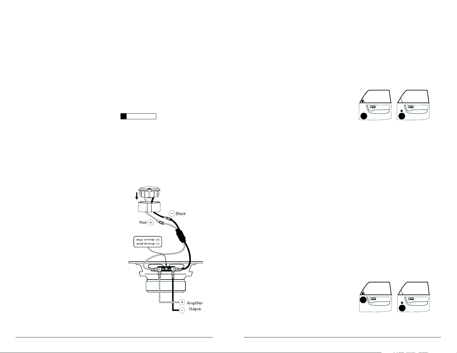
It is absolutely vital that your component
system is connected as shown in the diagram
below. Failure to connect the system as shown
will result in damage to your speakers which is
NOT covered under warranty. Do not substitute
different crossover networks or filters into your
TR650-CSi System. Only use in-line filters clearly
marked “TR050-CThp”.
WARNING
!!
2 JL AUDIO TR650-CSi
A) Wiring Diagram:
Page 3

INSTALLING THE WOOFERS IN
CUSTOM LOCATIONS:
Run speaker wire to the desired mounting
location. If you are running wires into a door, use
existing factory wiring boots whenever possible. If
you are drilling new holes, file their edges and install
rubber grommets into each hole. Then, cover the
wires with a protective PVC sleeve and run them
through the door jamb. Make sure that the wires
will clear door hinges and other structures in the
door. If you are unsure about any part of this
process, please contact your JL AUDIO dealer for
installation help.
Double check the clearance for both speakers
before proceeding.
Use the supplied template on the top of the
product packaging to mark the desired mounting
location. Mark the center and the outline of the
mounting hole as well as the mounting screw
positions. Before drilling or cutting, use a utility knife
to cut any fabric, vinyl or leather from hole
locations. These materials can easily be snagged by
a drill or a saw, causing damage to the panel and
possible bodily injury.
Drill four 1/8" (3 mm) holes for the speaker’s
mounting screws at the positions you have marked.
Also drill a pilot hole in the center of the speaker
mounting hole at this time. Then, using a saber saw,
hole saw or nibbler, make the circular cut out for
the speaker. File any rough edges.
Insert the mounting clips with the flat side
towards the speaker as shown in the diagram.
It is absolutely vital that the speaker frame fits
into the mounting hole cleanly. This must be
checked prior to tightening the screws. Do not
force the frame into a hole that is too small! Do
not tighten the speaker onto an uneven surface! This
will damage your speakers. The speaker should also
fit so that no air leaks around the mounting flange.
Air leaks will cause a severe degradation in sound
quality. Seal any air leaks with silicone, rope caulk or
similar sealant material.
Connect the speaker wires, observing correct
polarity, and install the speaker and grille tray as
shown.
Hand-tighten the screws evenly to avoid
bending the speaker frame!
Break off small pieces of the supplied butyl
adhesive putty and place them on the inside of each
grille tray. This adhesive will hold the grille in place
firmly and prevent rattling. Then inser t the metal
grille into the grille tray, squeezing gently around its
edge until it seats firmly into the tray.
JL AUDIO TR650-CSi 5
INSTALLING THE WOOFERS IN
FACTORY LOCATIONS:
If you will be using the factory speaker wires, it
may be necessary to change the terminations. This
may be accomplished by using an adaptor plug or
simply by cutting the factory connector off and
using the supplied crimp connectors to terminate
the speaker wires.The large connector is for the
positive terminal and the small connector is for the
negative terminal of each woofer. Make sure that
you observe correct polarity in your connections. If
you are unsure about any of these issues, contact
your JL AUDIO dealer for installation assistance.
Your new speakers have been designed to install,
without modifications, into most vehicles that accept
a 6.5-inch (160 mm) speaker. Most factory 6.5-inch
speakers use four mounting screws which will line
up with the mounting holes on your woofers.
Others use a 3-hole mounting system which is
accommodated by a separate set of mounting holes
on the frames of your TR650-CWi woofers.
It is absolutely vital that the speaker frame fits
into the mounting hole cleanly. This must be
checked prior to tightening the screws. Do not
force the frame into a hole that is too small! Do
not tighten the speaker onto an uneven surface! This
will damage your speakers. The speaker should also
fit so that no air leaks around the mounting flange.
Air leaks will cause a severe degradation in sound
quality. Seal any air leaks with silicone, rope caulk or
similar sealant material.
Install as shown in the diagram here.
Use the supplied mounting clips unless the
factory holes already feature threaded inserts.
Hand-tighten the screws evenly to avoid bending
the speaker frame!
4 JL AUDIO TR650-CSi
Page 4

FLUSH MOUNT INSTALLATION:
1) Remove the vehicle panel and check to
ensure that there is at least 3/4 inch (19mm)
clearance behind the panel for the tweeter’s
magnet structure.
2) Carefully cut a 1 9/16-inch (40 mm) diameter
hole in the vehicle panel.This will achieve a snug fit
and allow the tweeter flange to conceal the cut line.
3) Insert the tweeter from the front of the panel
(do not attach the spring clip at this time).
4) Attach the spring clip from behind the panel
using the supplied 1/4 inch (6 mm) machine screw.
5) Tighten the screw by hand until the tweeter is
tight on the panel. Do not over tighten.
6) Connect the tweeter’s wires to the supplied
harness with the in-line high-pass filter.
7) Re-install the vehicle panel, taking care to
route the new wiring so as not to interfere with
any vehicle mechanisms (window mechanisms,
for example).
JL AUDIO TR650-CSi 7
Tighten
Screw
Vehicle
Panel
Metal
Spring Clip
Tighten
Screws
Vehicle
Panel
Surface
Mount
Fixture
TWEETER INSTALLATION:
The dome tweeters supplied with your
TR650-CSi system have been designed for surface
or flush mounting. Before choosing a method,
carefully inspect the desired mounting location to
determine which method will work best.
1) Flush Mounting will yield a custom-installed
appearance, but will require at least 3/4-inch
(19 mm) of clearance behind the mounting
surface of the tweeter.
2) Surface Mounting, using the supplied surface
mount kit and hardware requires the drilling of
three holes (one for the wires and two for the
mounting screws).This application is useful when
mounting the tweeters to a panel that has
insufficient clearance behind it for the tweeter’s
magnet structure.
TWEETER CONNECTIONS:
Run the supplied wiring harness with the in-line
filter from the extra tabs on the component
woofer to the tweeter mounting location.Then
connect this harness to the wires attached to the
tweeters, observing correct polarity. In some
cases, it may be easier to run the tweeter wires
directly to the amplifier output, instead of
connecting them to the component woofer
terminals.This is functionally identical to the first
method (it is a simple, parallel connection).
See Wiring Diagram on page 2 for details.
SURFACE MOUNT INSTALLATION:
1) Remove the vehicle panel and check to
ensure that the mounting screws will have
adequate clearance.
2) Place the surface-mount fixture on the vehicle
panel at the desired mounting location and mark
the location of the two mounting screw holes and
the approximate center of one of the two
rectangular cutouts (for the wires).
3) Using a 1/16-inch (1.5 mm) drill bit, drill a hole
through the panel at the two screw locations.
4) Using a 1/2-inch (12 mm) drill bit, drill the
hole for the tweeter’s wires at the location you
marked in step 2.
5) Screw the surface mount fixture to the vehicle
panel using the supplied #6 sheet metal screws
(hand-tighten).
6) Feed the tweeter wires through the
rectangular hole in the mounting fixture and the
1/2-inch hole you drilled in the panel.Then, snap the
tweeter into the surface mount fixture.
7) Connect the tweeter’s wires to the supplied
harness with the in-line high-pass filter.
8) Re-install the vehicle panel, taking care to
route the new wiring so as not to interfere with any
vehicle mechanisms (window mechanisms,
for example).
6 JL AUDIO TR650-CSi
Page 5

JL AUDIO LIMITED WARRANTY (USA)
Evolution Speaker Systems
JL AUDIO warrants these speakers (and crossover networks, where applicable) to be free of defects in
materials and workmanship for a period of ninety (90) days from the original date of purchase. The warranty
term is extended to one (1) year if installation is performed or approved by an authorized JL AUDIO dealer
(proof of installation or approval required on purchase receipt).
This warranty is not transferrable and applies only to the original purchaser from an authorized JL AUDIO
dealer. Should service be necessar y under this warranty for any reason due to manufacturing defect or
malfunction, JL AUDIO will, at its discretion, repair or replace the defective product with new or remanufactured
product at no charge.
Damage caused by the following is not covered under warranty: accident, misuse, abuse, product modification
or neglect, failure to follow installation instructions, unauthorized repair attempts, misrepresentations by the seller.
This warranty does not cover incidental or consequential damages and does not cover the cost of removing or
reinstalling the unit(s). Cosmetic damage due to accident or normal wear and tear is not covered under warranty.
Any applicable implied warranties are limited in duration to the period of the express warranty as provided
herein beginning with the date of the original purchase at retail, and no warranties, whether express or implied,
shall apply to this product thereafter. Some states do not allow limitations on implied warranties, therefore these
exclusions may not apply to you. This warranty gives you specific legal rights, and you may also have other rights
which vary from state to state.
If you need service on your JL AUDIO product:
All warranty returns should be sent to JL AUDIO freight prepaid through an authorized
JL AUDIO dealer and must be accompanied by proof of purchase (a copy of the original sales receipt.) Direct
returns from consumers or non-authorized dealers will be refused unless specifically authorized by JL AUDIO
with a valid return authorization number. Warranty expiration on products returned without proof of purchase
will be determined from the manufacturing date code. Coverage may be invalidated as this date is previous to
purchase date. Return only defective components. If one speaker fails in a system, return only that speaker
component, not the entire system. Non-defective items received will be returned freight-collect. Customer is
responsible for shipping charges and insurance in sending the product to JL AUDIO. Freight damage on returns
is not covered under warranty.
For Service Information in the U.S.A. please call:
JL Audio customer service: (954)443-1100
during normal business hours (Eastern Time)
JL Audio, Inc
10369 North Commerce Pkwy.
Miramar, FL 33025
International Warranties:
Products purchased outside the United States of America are covered only
by that country’s distributor and not by JL Audio, Inc.
Printed in Taiwan
JLTR650CSi-01-2003
 Loading...