

JL Audio T2-500.1 Owner's Manual

Thank you for purchasing a Total Mobile Audio amplifier for
your automotive sound system.
Your amplifier has been designed and manufactured to exacting
standards in order to ensure years of musical enjoyment in your vehicle.
For maximum performance and extended warranty
coverage, we highly recommend that you have your new amplifier
installed by an authorized Total Mobile Audio dealer. Your authorized
dealer has the training, expertise and installation equipment to ensure
optimum performance from this product. Should you
decide to install the amplifier yourself, please take the time
to read this manual thoroughly so as to familiarize yourself
with its installation requirements and setup procedures.
If you have any questions regarding the instructions in this
manual or any aspect of your amplifier’s operation, please contact your
authorized Total Mobile Audio dealer for assistance. If you need further
assistance, please call our Technical Support Department
at (954) 443-1100 during business hours.
OWNER’S MANUAL
500W Monoblock Subwoofer Amplifier

2 Total Mobile Audio
3
PLANNING YOUR INSTALLATION
It is important that you take the time to read
this m anual and t hat you plan out your
insta llation caref ully. The followi ng are some
considerat ions that you must t ake into account
when plan ning your ins tallation.
Cooling Efficiency Consid erations:
The outer sh ell of your TMA amplifier is d esigned
to remove heat from the amplifier circuitry. For
optimum cooling performance, this outer shell
should be exposed to as large a volume of air
as possible. Enclosing the amplifier in a small,
poorly ventilated chamber can lead to excessive
heat build-up and degraded performance. If an
insta llation cal ls for an enclosure around the
amplif ier, we recommend that this enclosure
be ventil ated with the aid of a fan. I n normal
application s, fan-coolin g is not necessa ry.
Mounting t he amplifier upsi de down is
strongly discouraged.
If mounting the amplifier under a seat,
make su re there is at lea st 1 inch (2.5 c m) of
space above the amplif ier’s outer shel l to permit
proper coolin g.
Safety Considerations:
Your amplifier needs to be installed in a dry,
well-ventila ted environment a nd in a manner
which does not interfere with your vehicle’s safety
equipment (air bags, seat belt systems, ABS brake
systems, etc.). You should also take the time to
securely mount the ampli fier using appropr iate
hardware so that it does not come loose in t he
event of a co llision or a sudden jolt to the vehicle.
Stupid Mi stakes to Avoid:
• Check before drilling any holes in your vehicle
to make sure that you will not be drilling
throug h a gas tank , brake line, wiring har ness or
other v ital vehicle sys tem.
• Do not run system wiring outside or underneath
the vehic le. This is a n extremely da ngerous
practice which can result in severe damage to
your vehic le and person.
• Protect all system wires from sharp metal
edges and wear by carefully routing them,
tying them down and using grommets and
loom where appropriate .
• Do not mount the amplifier in the engine
compart ment, under the ve hicle, on the roof
or in a ny other area th at will exp ose the
amplifier circuitry to the elements.
PROTECT YOUR H EARING!
We value you as a long-term customer. For
that rea son, we urge you to pr actice restra int in
the oper ation of this produc t so as not to d amage
your hearing and that of others in your vehicle.
Studies have shown that cont inuous exposure to
high sound pressure levels can lead to permanent
(irrepara ble) hearing loss . This and a ll other
high-power a mplifiers ar e capable of producing
such hig h sound pressure le vels when connect ed
to a spea ker system. Plea se limit your continuous
exposu re to high volume le vels.
While driving, operate your audio system in
a manner that stil l allows you to he ar necessar y
noises to operate your vehicle safely (horns,
sirens, etc.).
SERIAL NUMBER
In the event that your a mplifier requi res
serv ice or is ever stolen, you will nee d to
have a record of the product’s serial number.
Please take the time to enter that number in
the space provided below. The serial number
can be found on the bot tom panel of the
amplif ier and on the amplifier pac kaging.
Serial Number:
INSTALLATION APPLICATIONS
This amplifier is designed for operation in
vehicles with 12V, negative-ground electrical
systems. Use of this product in vehicles with
positive ground and/or voltages other than 12V
may result in damage to the product and will void
th e w arr ant y.
This product is not certified or approved for
use in aircraft.
Do not att empt to “bridge” t he outputs of th is
amplif ier with the outputs of a second amplifier,
includin g an identical one.
Reversed | Normal
Output Polarity
LP Filter Frequency (Hz)Input Sens. Bass Boost
min max
40 130 O +12dB
Power
Remote
Level
Port
LEFT
RIGHT
LEFT
RIGHT
Preamp
Outputs
Amplifier
Inputs
a JL Audio® Company
Left & Right
Preamp Output Jacks
(pg. 8)
Left & Right
Preamp Input Jacks
(pg. 6)
Remote
Level Port
(pg. 8)
Power/Protection
Status Indicator
(pg. 9)
Output Polarity
Switch
(pg. 7)
Bass Boost
Control
(pg. 8)
Filter
Frequency Selecto r
(pg. 7)
Input Sensitivi ty
Control
(pg. 6)
Made in China
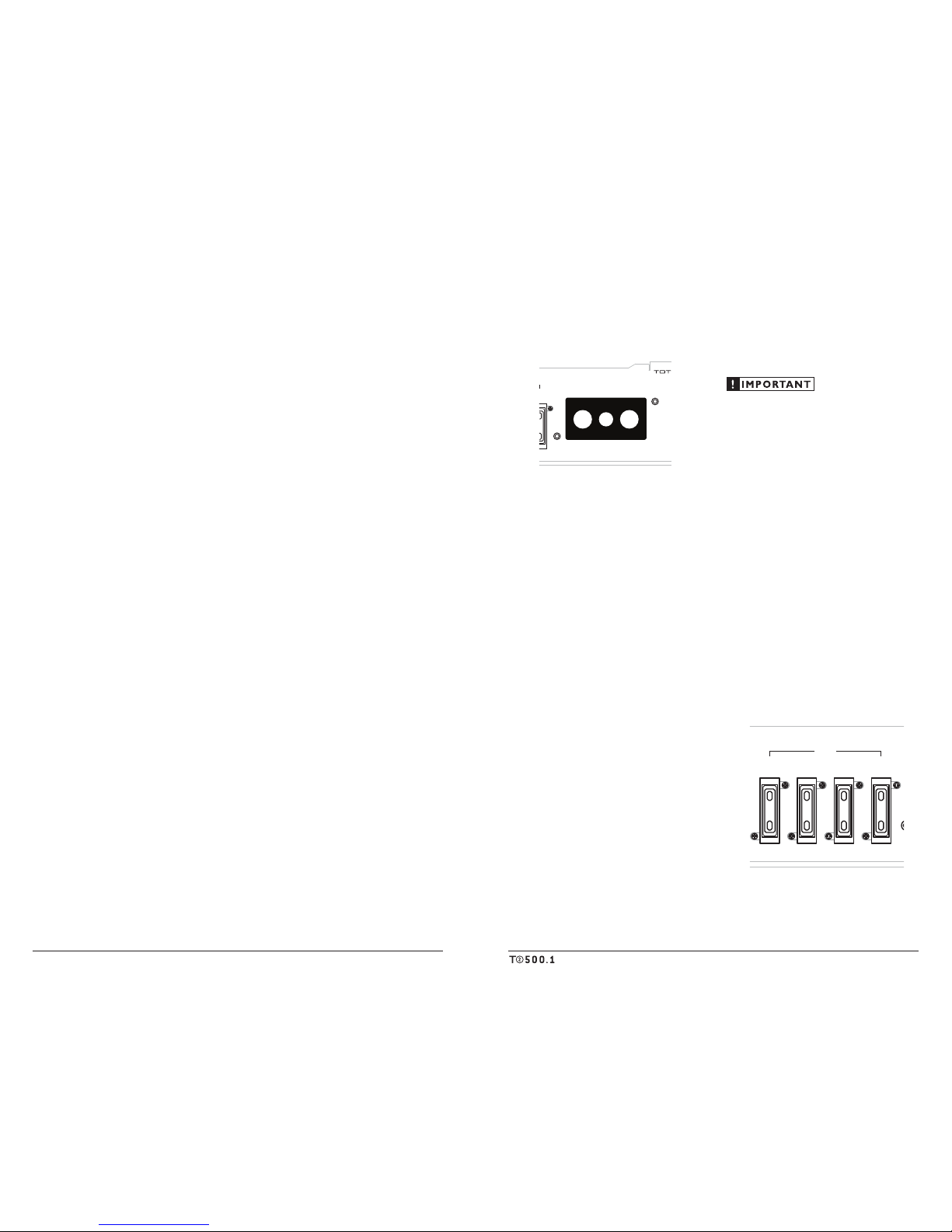
Speaker Output (Mono)FUSES + 12VDC
15A15A15A15A
Remote Ground
a JL Audio® Company
Chassis Ground
Connector
(pg. 5)
+12 V Power
Connector
(pg. 5)
Fuses
(pg. 5)
Remote Turn-On
Connector
(pg. 6)
Speaker Outputs
(pg. 9)
4 Total Mobile Audio
5
POWER CONNECTIONS
Before installing the amplifier, disconnect the
negative (ground) wire from the vehicle’s battery.
This will prevent accidental damage to the system,
the vehic le and your person during insta llation.
Speaker Output (Mono)FUSES + 12VDC
Remote Ground
a JL Audio® Company
The T2-50 0.1’s “+12 V DC ” (positi ve) and
“Ground” (ground) connections are designed to
accept 4 AWG power w ire. 4 AWG is a minimu m
power wire size for this amplifier.
If you are installing the T2-500.1 with other
amplif iers and wish to use a single main power
wire, use 2 AWG or 1/0 AWG main power wire
(depending on the overall current demands of
all the amplifiers in the system). This 2 AWG
or 1/0 AWG power wire shou ld terminate i nto
a distribution block mounted as close to the
amplifiers as possible and should connect to the
T2-500.1 with 4 AWG power wire.
Note: that smaller AWG numbers mean bigger
wire and vice-versa (1/0 AWG is the largest,
2 AWG is smaller, then 4 AWG, then
8 AWG, etc.).
To connect the power and ground wires to the
amplifier, strip 1/2-inch (12 mm) of insulation
from each wire and insert the bare wire into the
the appropriate terminal block positions on the
T2-500.1. Use a Phillips screwdriver to secure the
wire via the screw on the top of each terminal.
The “Ground” connection should be made
using 4 AWG wire and should be kept as short
as possible, while accessing a solid piece of sheet
metal i n the vehicle. T he surface of t he sheet
metal s hould be sanded at the contact poi nt
to create a clean, metal-to-metal connection
between the chassis and the termination of
the ground wire. The use of a star washer to
lock down the connection is advisable.
Any wires run through metal barriers (such as
firewa lls), must be protec ted with a hi gh quality
insulat ing grommet to prevent damage to t he
insulation of the wire. Failure to do so may result
in a dangerous short circuit.
Many vehicles employ small (10 AWG -
6 AWG) wire to ground the battery to the
vehicle chassis and to connect the alternator’s
positive con nection to the bat tery. To prevent
voltage drops, these wires should be upgr aded
to 4 AWG (or larger) when installing a
T2-5 00.1.
FUSE REQUIREMENTS
While the T2-500.1 has four 15A ATC fuses
on its power connection panel, these do nothing
to protect the vehicle from a dangerous short
circuit in the power wire. They only protect the
amplifier. It is absolutely vital that the main
power lead to the amplifier(s) in the system be
fused within 18 inche s (45 cm) of t he positive
battery post connection. The fuse value at each
power wire should be high enough for all of the
equipment being run from that power wire.
If only t he T2-500.1 is be ing run from that power
wire, we recommend a 60A fuse be used. AFS or
MAX I-type fuse s are recommended .
Speaker Output (Mono)FUSES + 12VDC
15A15A15A15A
Remote Ground
a JL Audio® Company
PRODUCT DESCRIPTION
The TMA T2-500.1 is a monoblock
subwoofer amplifier utilizing Class B
technology. Its frequency response is limited
to the range below 125 Hz. It is not designed
for driving midrange speakers or tweeters.
It has bee n optimized for low-frequency
amplif ication. For deta iled specif ications,
please refer to Appendix B (pa ge 13).
TYPICAL INSTALLATION SEQUENCE
The following represents the sequence
for a ty pical amplif ier instal lation, using a n
after market source u nit or OEM Interfa ce
product. Additional steps and different
procedures may be required in some applications.
If you have a ny questions, ple ase contact your
authorized TMA dealer for assistance.
1) Disconnec t the negative b attery post
connection and secure the disconnected cable
to prevent accidental re-connection during
insta llation. This step is not optiona l!
2) Run power w ire (minimum 4 AWG)
from the battery location to the amplifier
mounting location, taking care to
route it in such a way that it will not be
damage d and will not interfere with
vehicle oper ation. Use 2 AWG or 1/0
AWG power w ire if additiona l amplifiers
are being installed with the T2-500.1.
3) Con nect power wire t o the positive bat tery
post. Fuse the wire with an appropriate fuse
block (and con nectors) within 18 inches (45
cm) wire length of the positive battery post.
This f use is essentia l to protect the ve hicle.
Do not install the fuse until the power wire
has been connected to the amplifier.
4) Run signal cables (RCA cables) and remote
turn-on wire from the source unit to the
amplifier mounting location.
5)
Run speaker wire from the speaker systems
to the a mplifier mount ing location.
6)
Find a good, solid metal grounding point
close to t he amplifier and connect t he negative
power wire to it using appropri ate hardware.
Use mini mum 4 AWG power wi re, no longer
than 3 6 inches (90 cm) from the amplifie r to
the grou nd connection poi nt. In some vehicle s,
it may be ne cessary to up grade the bat tery
ground w ire. (See page 5 for important notic e).
7)
Securely mount the amplifier using
appropriate hardware.
8)
Conne ct the positive and negative power
wires t o the amplif ier.
9)
Conne ct the remote tu rn-on wire
to the a mplifier.
10)
Conne ct the RCA input c ables
to the a mplifier.
11)
Conne ct the speak er wires to t he amplifier.
12)
Carefully review the amplifier’s control
setti ngs to make sure that they a re set according
to the needs of the system.
13)
Install power wire fuse (60A for a single T2-500.1)
and recon nect the negative battery post terminal.
14)
Turn on t he source unit at a low level
to double-che ck that the a mplifier is con figured
correct ly. Resist the temptation to c rank it up
until you have verified the control sett ings.
15)
Mak e necessary adjustments to the input
sensitiv ity controls to obt ain the rig ht
overall output and the de sired balance
in the system. See Appe ndix A (page 12)
for the rec ommended input sensit ivity
setting method.
16)
Enjoy t he fruits of you r labor with your
favorite music .
 Loading...