

JL Audio StealthMod SMS-B-X5E70 Installation Manual
INSTALLATION GUIDE
for the
SMS-B-X5E70
SKU# 94518
2007 - Up
Thank you for choosing a JL Audio StealthMod® for your automotive sound system. With
proper installation, your new vehicle-specific enclosed subwoofer system will deliver
years of listening pleasure.
We strongly recommend that you have your new StealthMod
®
system installed by your
authorized JL Audio dealer. The installation professionals employed by your dealer have
the necessary tools and experience to disassemble and reassemble your vehicle properly.
Also, keep in mind that your warranty coverage extends to 2 years if your system is
installed or approved by your authorized JL Audio dealer. If you prefer to perform your
own installation, please read this installation guide completely
before beginning the process.
If you choose to per form the installation yoursel f, it is abso lutely vital that the
StealthMod
®
system be prop erly mounted to the vehicle according to these
instructions . Failure to mount the enclosure prop erly presents two problems:
1) The sub-bass per formance will suffer due to the movement of the enclosure
caused by the force exe rted by the woofer(s).
2) A loose enclosure pres ents a serious safety haza rd in the event of a collision
or sudden deceleration.
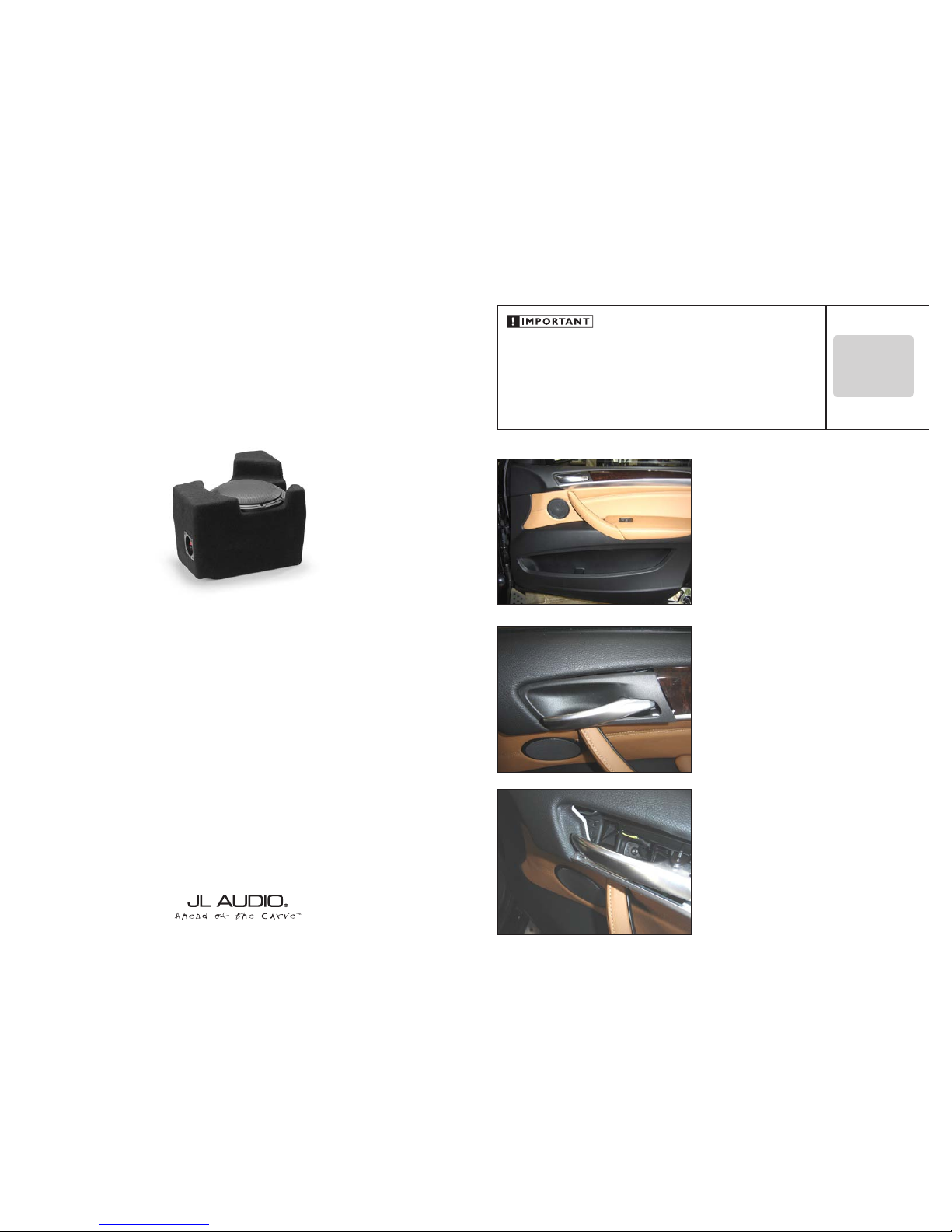
STEP 1
Roll down the window and open the passenger door.
Continued on Next Page
STEP 2
Carefully pry up on the trim piece around the release handle
and remove it from the vehicle.
STEP 3
Remove the screw behind the panel.
SMS-B-X570 INST R_SKU# 11339
IN STALL ATIO N
DIFFICULTY:
5
5
OUT
OF
ESTIMATED TIME:
45 HOURS
StealthMod
®

Continued on Next Page
SMS-B-X5E70 INST R_SKU#11339
STEP 7
With the door panel removed, unclip the front of the upper
door trim as shown.
STEP 6
Remove the two screws on the underside of the door panel.
Starting at the bottom, unclip the door panel f rom the door,
unplug the wiring harnesses, and remove the door panel
from the vehicle.
STEP 5
Remove the two screws under the panel.
STEP 4
Carefully pry of f the trim on the pull handle and remove it
from the vehicle.
Page 2 • JL Audio, Inc 2012
STEP 9
Pictured is the back side of the door panel. Cut a small
piece of the Foam Tape and apply it to the panel as shown.
Remove the screw indicated, and retain it for use in S tep 11.
STEP 11
Slide a pair of Speed Clips over the holes in the Crossover
Bracket. Place the bracket over the two pieces of Foam
Tape, aligning the holes with the clip and speaker mounting
hole. Secure the bracket to the door panel with the screw
removed in Step 9.
STEP 10
Cut a second piece of the Foam Tape and apply it to the
panel, over the clip as shown.
STEP 8
Unclip the rear of the upper door trim as shown, and remove
the panel from the vehicle.
Continued on Next Page
SMS-B-X5E70 INST R_SKU#11339
STEP 15
Reinstall the upper door trim with the tweeter wires exiting
from the bottom as shown. Extend the positive and
negative tweeter wires as necessary, and onnec t them to the
Tweeter Output (T+ and T-) of the Crossover.
Plug in the factor y harnesses and reinstall the door panel.
STEP 14
Mount the C5 Tweeter into the surface mount cup, and
install the assembly into the factory provision as shown. An
adhesive is recommended to secure the assembly. Reinstall
the foam with the tweeter wires exiting from the b ottom.
STEP 13
Remove the foam from the upp er door trim to access the
factory t weeter. Unclip and remove the tweeter.
STEP 12
Cut two more pieces of Foam Tape, and apply them to the
Crossover Bracket, then mount the Crossover to the bracket
using a pair of #8 x 3/4” Phillips Head Screws.
Cut the factory midrange wires with enough length to reach
the Crossover. Connect the White positive and White/Blue
negative wires from the factory midrange to the Woofer
Output (W+ and W-) of the Crossover. Connect the other
end of the cut factor y midrange wires to the Input (In + and
In -) of the Crossover.
Page 3 • JL Audio, Inc 2012
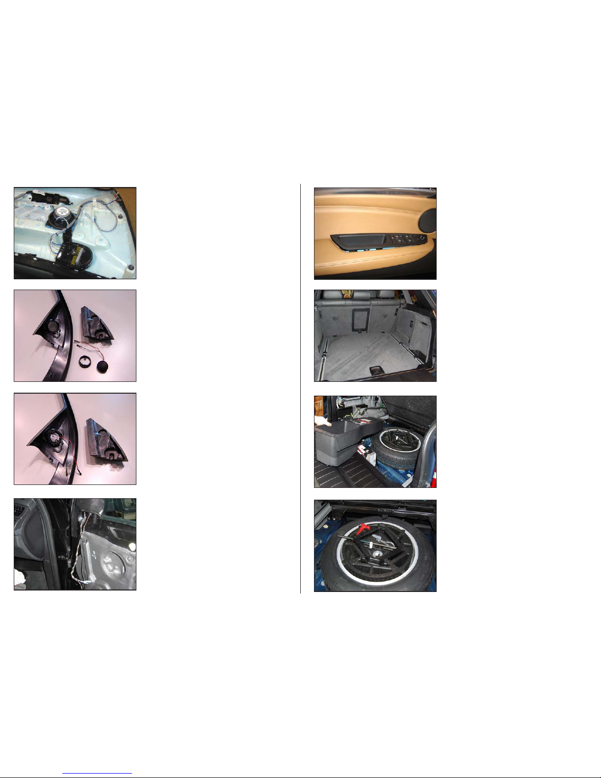
STEP 17
Empty out the cargo area so that you have a clean area to
work in.
STEP 19
The tools can be relocated to the foam tray inside the spare
tire.
STEP 18
Remove the cargo flo or panel. Remove the two screws on
the battery cover, and remove the cover. Remove the screw
holding in the storage tray, and remove the tray.
STEP 16
Repeat the Crossover and Tweeter installation for the driver’s
side beginning by following the procedure outlined in Steps
1-3.
Remove the screw from inside the door cup, and
carefully unclip the switch panel as shown. Unplug the
harnesses and remove the panel.
Continue by following the procedure outlined in Steps
6-1 5. The factory midrange has a Yellow positive wire and a
Yellow/Black negative wire.
 Loading...