

Thank you for purchasing a JL Audio amplifier for
your automotive sound system.
Your amplifier has been designed and manufactured to exacting
standards in order to ensure years of musical enjoyment in your vehicle.
For maximum performance and extended warranty
coverage, we highly recommend that you have your new amplifier
installed by an authorized JL Audio dealer. Your authorized
dealer has the training, expertise and installation equipment to ensure
optimum performance from this product. Should you
decide to install the amplifier yourself, please take the time
to read this manual thoroughly so as to familiarize yourself
with its installation requirements and setup procedures.
If you have any questions regarding the instructions in this
manual or any aspect of your amplifier’s operation, please contact your
authorized JL Audio dealer for assistance. If you need further assistance,
please call the JL Audio Technical Support Department
at (954) 443-1100 during business hours.
OWNER’S MANUAL
A120 0
monoblock full-range amplifier
PLANNING YOUR INSTALLATION
It is important that you take the time to read
this manual and t hat you plan out your
installation carefu lly. The following are some
considerations that you must take into account
when planning your installation.
Cooling Ef ficiency Consi derations:
The outer shell of your JL Audio amplifier
is designed to remove heat from the amplifier
circuit ry. For optimum cooling per formance,
this outer shell should be exposed to as large a
volume of air as possible. Enclosing the a mplifier
in a smal l, poorly ventilated cha mber can
lead to excessive heat build-up and degraded
performance. If an installation calls for an
enclosure around the amplifier, we recommend
that this enclosure be ventilated with the aid
of a fan. In normal applications, fan-cooling
is not necessa ry.
Mounting the amplifier upside down is
strongly discouraged.
If mounting the ampli fier under a seat,
make sure t here is at least 1 inch (2.5 cm) of
space above the amplif ier’s outer shell to permit
proper cooling.
Safety Considerations:
Your amplifier needs to be installed in a dry,
well-ventilated envi ronment and i n a manner
which does not interfere with your vehicle’s safety
equipment (air bags , seat belt systems, ABS brake
systems, etc.). You should also take the time to
securely mou nt the amplifier using the supplied
screws so that it does not come loose i n the event
of a collision or a sudden jolt to the vehicle.
Stupid Mistakes to Avoid
• Check before drill ing any holes in your vehicle
to make sure that you will not be drilling
through a gas tan k, brake line, wiring harness or
other vital vehicle system.
• Do not run system wir ing outside or underneath
the vehicle. This is an extremely dangerous
practice which can result in severe damage to
your vehicle a nd person.
• Protect all system w ires from sharp metal
edges and wea r by carefully rout ing them,
tying them down a nd using grommets and
loom where appropriate.
• Do not mount the ampl ifier in the engi ne
compart ment, under the vehicle, on the roof
or in any other area that will expose the
amplif ier circuitry to t he elements.
JL AUDIO A1200 3
PROTECT YOUR HEARING!
We value you as a long-term customer. For
that reason, we urge you to practice restraint in
the operation of this produc t so as not to damage
your hearing and that of others in your vehicle.
Studies have shown that continuous exposure to
high sound pressure levels can lead to permanent
(irreparable) hearing loss. This and a ll other
high-power ampli fiers are capable of producing
such high sound pressure levels when connected
to a speaker system. Please limit your conti nuous
exposure to high volume levels.
While driving, operate your aud io system in
a manner that stil l allows you to hear necessary
noises to operate your vehicle safely (horns,
sirens, etc.).
SERIAL NUMBER
In the event that your ampli fier requires
service or is ever stolen, you will need to have
a record of the product’s serial number. Please
take the time to enter that number in the space
provided below. The serial number can be fou nd
on the bottom panel of the amplifier and on the
amplifier packaging.
Serial Number:
INSTALLATION APPLICATIONS
This ampl ifier is designed for oper ation in
vehicles with 12 volt, negat ive-ground electrical
systems. Use of this product in vehicles w ith
positive ground and/or voltages other than 12V
may result in damage to the product and will void
the warranty.
This product is not cert ified or approved for
use in aircraft.
Do not attempt to “ bridge” the outputs of this
amplif ier with the outputs of a second amplif ier,
including an identical one.
2 JL AUDIO A1200
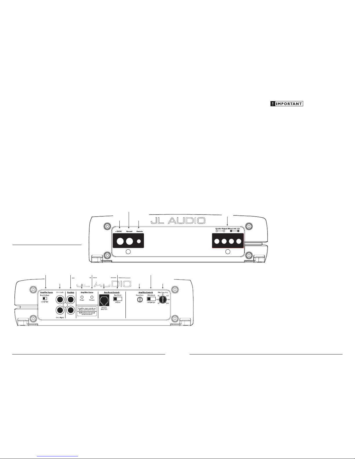
Left & Right
Preamp Input Jacks
(pg. 6)
Protection Status
Indicator
(pg. 11)
Left & Right
Preamp Output Jacks
(pg. 9)
Input Voltage
Selection
(pg. 7)
Power Status
Indicator
(pg. 11)
Bass EQ
On/Off Switch
(pg. 9)
Jack for
Remote Bass
Control Knob
(pg. 9)
Filter Mode
Selection
(pg. 7)
Filter
Frequency Selector
(pg. 7)
Input Sensitivity
Control
(pg. 7)
Remote Turn-On
Connector
(pg. 6)
Chassis Ground
Connector
(pg. 5)
+12 V Power
Connector
(pg. 5)
Speaker Outputs
(pg. 10)
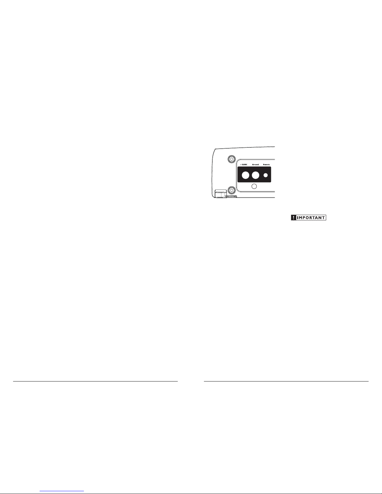
POWER CONNECTIONS
Before insta lling the amplifier, disconnect t he
negative (g round) wire from the vehic le’s bat tery.
This will prevent ac cidental damage to t he system,
the vehicle a nd your body during instal lation.
The A1200’s “+12V DC ” and “Ground”
connections are designed to accept 8 AWG 4 AWG power wire. 8 AWG is a minimum power
wire size for this amplifier.
If you are install ing the A1200 with ot her
amplif iers and wish to use a single main power
wire, use 4 AWG or larger main power wi re
(depending on the overall current demands of all
the ampli fiers in the system). This 4 AWG or
larger power w ire should terminate into a
distribution block mounted as close to t he
amplif iers as possible a nd should connect to the
A1200 wit h 8 AWG - 4 AWG power wire.
Note: that sma ller AWG numbers mean bigger
wire and v ice-versa (1/0 AWG is the la rgest, 2
AWG is smalle r, t hen 4 AWG , th en
8 AWG, etc.).
To connect the power wires to the a mplifier,
first back out the set screw on the top of t he
termina l block, using the supplied 2 .5 mm hex
wrench. St rip 1/2 inch (12 mm) of insu lation from
the end of each w ire and insert the bare wire i nto
the termi nal block, seating it f irmly so that no
bare wire is exposed . While holding the wi re in
place, tig hten the set screw fir mly, taking care not
to strip the head of the screw.
The ground connection should be made using
the same gauge wire as t he power connection
and should be kept as short as possible, while
accessing a solid piece of sheet metal in the
vehicle. The surface of the sheet met al should
be sanded at t he contact point to create a c lean,
metal-to-metal connection bet ween the cha ssis
and the termination of t he ground wire. For
optimal groundi ng, we recommend the use of a
JL Audio ECS ma ster grou nd lug (XA-MGL-1).
Alternat ively, a sheet meta l screw or bolt ca n be
used with a star washer.
Any wires r un through metal barriers (such
as firewalls), must be protected with a high
qualit y rubber grommet to prevent da mage to the
insulat ion of the wire. Failure to do so may result
in a dangerous short ci rcuit.
Many vehicles employ small (10 AWG 6 AWG) wire to grou nd the battery to the
vehicle chas sis and to connect the alternator’s
positive connection to the battery. To prevent
voltage drops, these wi res should be upgraded
to 4 AWG when installing amplifier systems
with main fuse ratings above 60A.
FUSE REQUIREM ENTS
It is absolutely vital that the main power
wire(s) to the ampli fier(s) in the system be
fused w ithin 18 inches (45 cm) of the positive
battery post connection. The fuse va lue at each
power wire shou ld be high enough for all of the
equipment being run from that power wi re. If
only the A120 0 is being run from t hat power
wire, we recommend a 25A fuse b e used. A NL
(big blade fuse), AFS (small blade fuse), AGU (big
glass fuse) or MaxiFuse™ (big plastic-body fuse)
types are recommended.
No fuse is required or recommended direct ly
before the ampl ifier power connection. If one is
desired, we recommend the u se of a 25A AGU,
AFS or MaxiFuse™ type.
JL AUDIO A1200 5
PRODUCT DE SCRIPTION
The JL Audio A120 0 is a monoblock,
full-range amplifier ut ilizing patented Absolute
Symmetr y™ Class A/B technology.
The A1200 can be operated with a w ide variety
of source units and system configurations.
TYPICAL I NSTALLATION SEQUE NCE
The followi ng represents t he sequence
for a typical ampli fier installation, using an
after market source unit or OEM Interface
processor ( like t he CleanSweep CL441dsp).
Additiona l steps and different procedures may
be required in some applications. If you have
any questions, please cont act your authorized
JL Audio dealer for assistance.
1) Discon nect the negative batter y post
connection and secure the disconnected cable
to prevent accidental re-connection during
installation. This step is not optional.
2) Run power wi re (minimum 8 AWG) f rom the
battery location to the amplif ier mounting
location, taking care to route it in such a
way that it wi ll not be damaged and will not
interfere w ith vehicle operation. Use 4 AWG
or larger power w ire and a power distribution
block if additional ampli fiers are being
installed with the A1200.
3) Connect power wire to t he positive battery
post. Fuse t he wire with an appropriate fuse
block (and connectors) within 18 inches (45
cm) wire length of the positive battery post.
This fu se is essential to prote ct the vehicle.
Do not insta ll the fuse unti l the power wire
has been sec urely connected to the ampl ifier.
4) Run signa l cables and remote turn-on w ire
from the source unit to t he fina l amplifier
mounting location.
5) Run speaker cables from the spea ker systems
to the ampli fier mounting location.
6) Find a good, sol id metal grounding point
close to the a mplifier and connec t the
negative power wire to it using appropriate
hardware (use of the JL Audio ECS master
ground lug , XA-MGL-1 is recommended).
Use the same size power wire as the w ire
connected to the “+12V DC ” connec tion
(minimum 8 AWG), no longer than 36 inches
(90 cm) from the amplifier to t he ground
connection point. In some vehicles, it may be
necessary to upgrade the battery grou nd wire.
(See page 5 for important notice).
7) Securely mount the ampli fier usi ng the
supplied screws.
8) Connect the positive and negative power
wires to the amplif ier. A fuse near the
amplif ier is not necessary.
9) Connect the remote turn-on wire
to the amplifier.
10) Connec t the input cables to the ampl ifier.
11) Con nect the speaker cables to the amplifier.
12) Carefu lly review the amplifier’s control
settings to make sure that they are set
according to the needs of t he system.
13) Instal l the power wire fuse (25A for a
single A120 0) and reconnec t the negative
battery post terminal.
14) Turn on the source unit at a low level
to double-check that the amplifier is
configured correctly. Resist the temptation
to crank it up until you have verified the
control settings.
15) Make necessary adjustments to the input
sensitivity controls to obtain the right
overall out put and the desired balance
in the system. See Appendix A (page 12)
for the recommended input sensit ivity
setting method.
16) Enjoy the f ruits of you r labor with your
favorite music.
4 JL AUDIO A1200
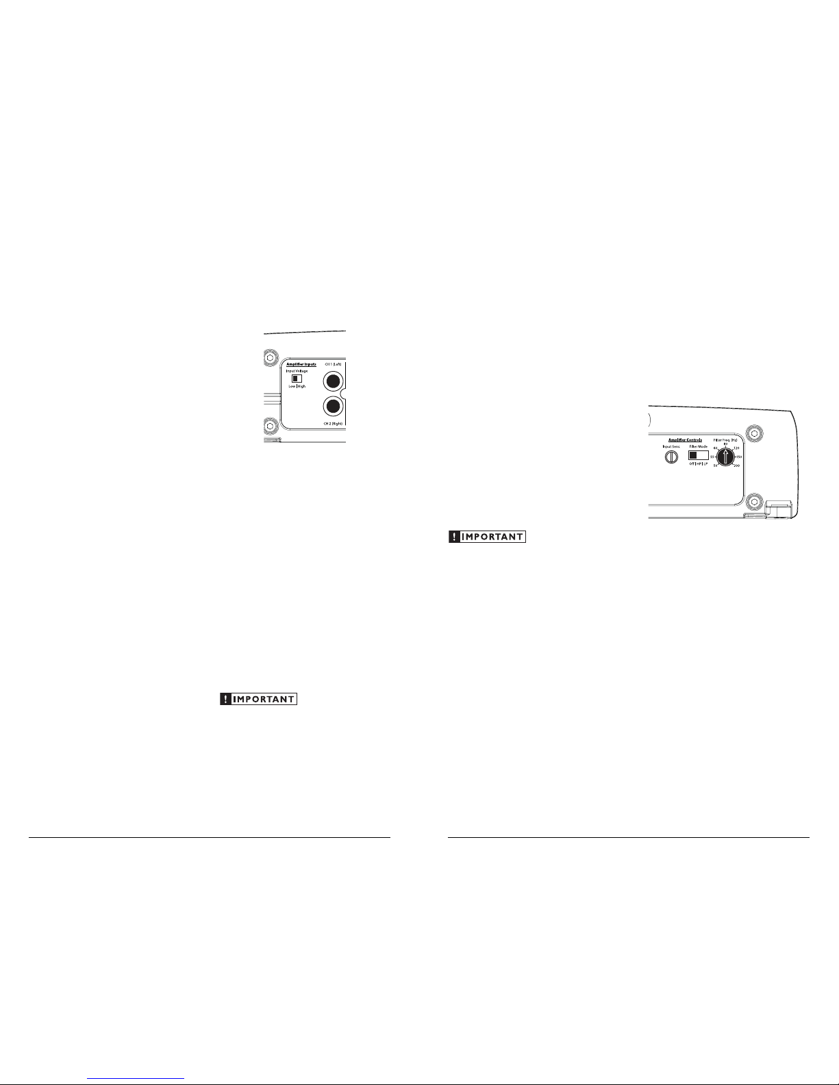
INPUT VOLTAGE RANGE:
A wide range of signal i nput voltages ca n be
accommodated by the A1200’s input section
(200mV – 8V). This wide ra nge is split up into
two sub-ranges, accessible via a sw itch located to
the left of the Input Connectors.
The “Low” position on the “Input Voltage”
switch selects an input sensitiv ity range between
200mV and 2V. This means that the “Input
Sens.” rotary control will operate with in that
voltage window. If you are using an aftermarket
source unit or an OEM interface proc essor with
conventional preamp-level outputs, this is most
likely the position that you will use.
The “High” position on the “Input Voltage”
switch selects an input sensitiv ity range between
800mV and 8V. This is usef ul for certain highoutput preamp level signals as well as speaker-level
output from source units and small a mplifiers.
To use speaker-level sources, splice the speaker
output wires of the source u nit or smal l amplifier
onto a pair of RCA plugs. No line output
converter is needed in most cases.
The output of the ampl ifier will decrease for
a given input voltage when the “Input R ange”
switch is placed in the “High” position.
Conversely, the output will be higher with the
switch in t he “Low” position. Wh ile this may
sound counter-i ntuitive, it is consistent w ith
the descriptions above.
AMPLIFIER CONTROLS
1) “I nput Se ns.”: Once the appropriate “Input
Vol ta ge ” range has been selected, the control
labeled “Input Sens.” located in the “Amplifier
Controls” section ca n be used to match the
source unit’s output voltage to the i nput
stage of the a mplifier for maxi mum clean
output. Rotating the cont rol clockwise will
result in higher sensit ivity (louder for a given
input voltage). Rotating the control counterclockwise will result i n lower sensitiv ity
(quieter for a given input voltage.)
To properly set the ampli fier for maximum
clean output , please refer to Appendix A (page
12). After usi ng this procedure, you c an then
adjust the “Input Sens.” level downwa rd if this is
required to ach ieve the desired system balance .
Do not increase any “Input Sens.” setti ng
for any channe l(s) of any a mplifier in the
system beyond t he maximum level est ablished
during t he procedure outlined i n Appendix
A (page 12). Doing so will result in audible
distortion a nd possible speaker dam age.
JL AUDIO A1200 7
TURNON LEAD
The A1200 uses a conventiona l +12V remote
turn-on lead, ty pically controlle d by the source
unit’s remote tur n-on output. The amplif ier wil l
turn on when +12V is present at its “Remote”
input and turn off when +12V is switched off. If
a source unit does not have a dedic ated remote
turn-on out put, the amplifier’s turn-on lead can
be connected to +12V via a switch that derives
power from an ignition-switched circuit.
The A1200’s “Remote” tu rn-on connector is
designed to accept 18 AWG – 12 AWG wire. To
connect the remote turn-on wire to t he amplif ier,
first back out the set screw on the top of t he
termina l block, using the supplied 2 .5 mm hex
wrench. Strip 1/2 inch (12mm) of wire and insert
the bare wire into the termina l block, seating it
firmly so that no bare wire is exposed. While
holding the w ire in the terminal, tig hten the set
screw firmly, tak ing care not to strip the he ad of
the screw and maki ng sure that the wire is firm ly
gripped by t he set screw.
INPUT SECTION
The A1200’s input sec tion al lows you to send
signal to t he amplifier section through the use
of two dif ferential-balanc ed inputs, one for t he
left channel signa l and one for the right channel
signal. Connection is via RCA-type jacks.
You may run a stereo or a mono signal into
the inputs of t he amplif ier. The amplifier’s input
section automatical ly sums stereo signals to mono
for the internal ampli fier section.
The amplifier wi ll operate with only one i nput
connection (left or right), but will require an
increase in input sensit ivity to overcome the loss
of signal. If a mono input signal is to be run, we
recommend that you use a “Y-adaptor” to split t he
mono signal into both inputs of the amplifier.
Left Cha nnel Only or Right Chan nel Only
Information: If you wish to send a Left-on ly or
Right-only signal to the A1200, use a “Y-Adaptor”
to split the single channel signal into both left
and right RCA i nputs. This option is useful
when using one A120 0 to drive the left cha nnel
speakers only and another A1200 to drive right
channel speakers only.
If you plan to use t he “Pre-Outs” to feed
a stereo amplifier, you must connect a
stereo signa l to the input of the amplifier.
A mono signal into the amplif ier will result
in a mono signa l out of the preamp output.
(It’s a great amplif ier, but it doesn't do magic).
6 JL AUDIO A1200
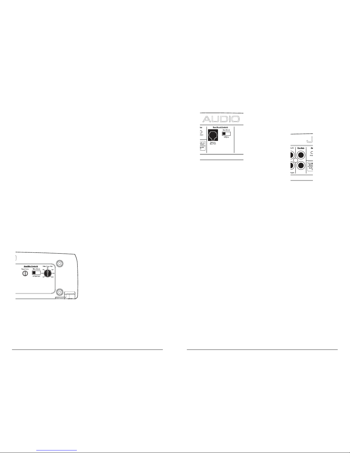
BASS BOOST CONTROLS
1) “B ass Bo ost”: This switch allows the user
to activate a 6 dB boost centered at 48 Hz.
The “Filter Mode” switch i n the “Amplifier
Controls” section must be in the “LP” position
for the bass boost to be fu nctional.
2) “Remote Bass Port ”: This port allows you to
connect an opt ional remote boost knob (sold
separately, JL Audio Model R BC-1) that can
be mounted in t he front of the vehicle. With
the RBC-1 connected, the boost is no longer
limited to 0 or +6 dB, allowing a r ange of
0 - 12 dB of boost to be selected.
PREOUTS
The A1200’s “Pre-Outs” connectors output
unprocessed (pass-th rough) left and right cha nnel
preamp level signals, permitting connection of
additional amplifiers in a system.
The preamp output signal s are identical to
the input signals and are not affected by any
settings in the “Amplifier Controls” or “Bass
Boost Controls” sections. The signal level of
the “Preamp Output” is line-level (low voltage),
regardless of the position selected via the A1200’s
“Input Voltage” switch. An additional amplifier
connected to these prea mp outputs should have
its input voltage switch set to t he “Low“ position.
JL AUDIO A1200 9
Filter Cont rols
Most speakers are not designed to reproduce
the full range of f requencies audible by the
human ear. For this reason, most spea ker
systems are comprised of mu ltiple speakers, each
dedicated to reproducing a specific f requency
range. Filters are used to select which frequenc y
range is sent to each section of a spea ker system.
The division of frequenc y ranges to different
speakers can be done with passive filters (coils
and/or capacitors between t he amplifier outputs
and the speakers), which a re acceptable and
commonly us ed for filtering between midrange speakers and tweeters. Filteri ng between
subwoofer systems and satellite speaker sy stems
is best done with active filters, which cut off
frequency c ontent at the input to t he amplifier.
Active filters are more stable than passive filters
and do not introduce extra neous resistance,
which can degrade subwoofer perfor mance.
The active filter built into t he A1200 can be
used to eli minate potential ly harmful and/or
undesired f requencies from making their way
through the ampli fier section to the speaker(s).
This ser ves to improve tonal bala nce and to avoid
distortion and possible speaker failure. Correct
use of thi s filter can substantially increase t he
longevity a nd fidelity of your audio system.
2) “Filter Mode” Control: The A1200 employs
a 12dB per octave filter. This filter ca n be
config ured into one of two filter type s or
defeated completely by way of the threeposition “Filter Mode” switch:
“Off”: Defeats t he filter completely, allow ing
the fu ll range of frequencies pre sent at the inputs
to feed the amplifier. This is useful for systems
utilizing outboard crossovers or requiring f ullrange reproduc tion from the A1200.
“LP” (Low-Pass): Configures the filter to
attenuate frequencies above the selected f ilter
frequency at a rate of 12dB per octave. Usef ul
for connection of subwoofer(s) to the A1200 in
a bi-amplif ied system.
“HP” (High-Pass): Config ures the filter to
attenuate frequencies below the selected filter
frequency at a rate of 12dB per octave. Usef ul
for connection of a coaxial or component
satellite speaker system to t he A1200 in a biamplified system.
3) “Filter Freq. (Hz)” The filter frequency
markings surrounding this rotary control
are for reference purposes a nd are generally
accurate to within 1/3 octave or b etter. If you
would like to select the filter cutoff frequency
with a higher level of precision, consult t he
chart in Appendix B (page 13).
Tun in g Hi nt: I f you are using the A1200 to d rive
a subwoofer system (“LP” mode) or a component
satellite speaker system (“HP” mode), 80 Hz is a
good baseline “Filter Freq. (Hz)” setting. After
properly adjusting the “Input Sens.”, as ou tlin ed
in Appendix A (page 12), you can fi ne tune the
“Filter Freq. (Hz)” control to achieve t he desired
system frequency response.
8 JL AUDIO A1200
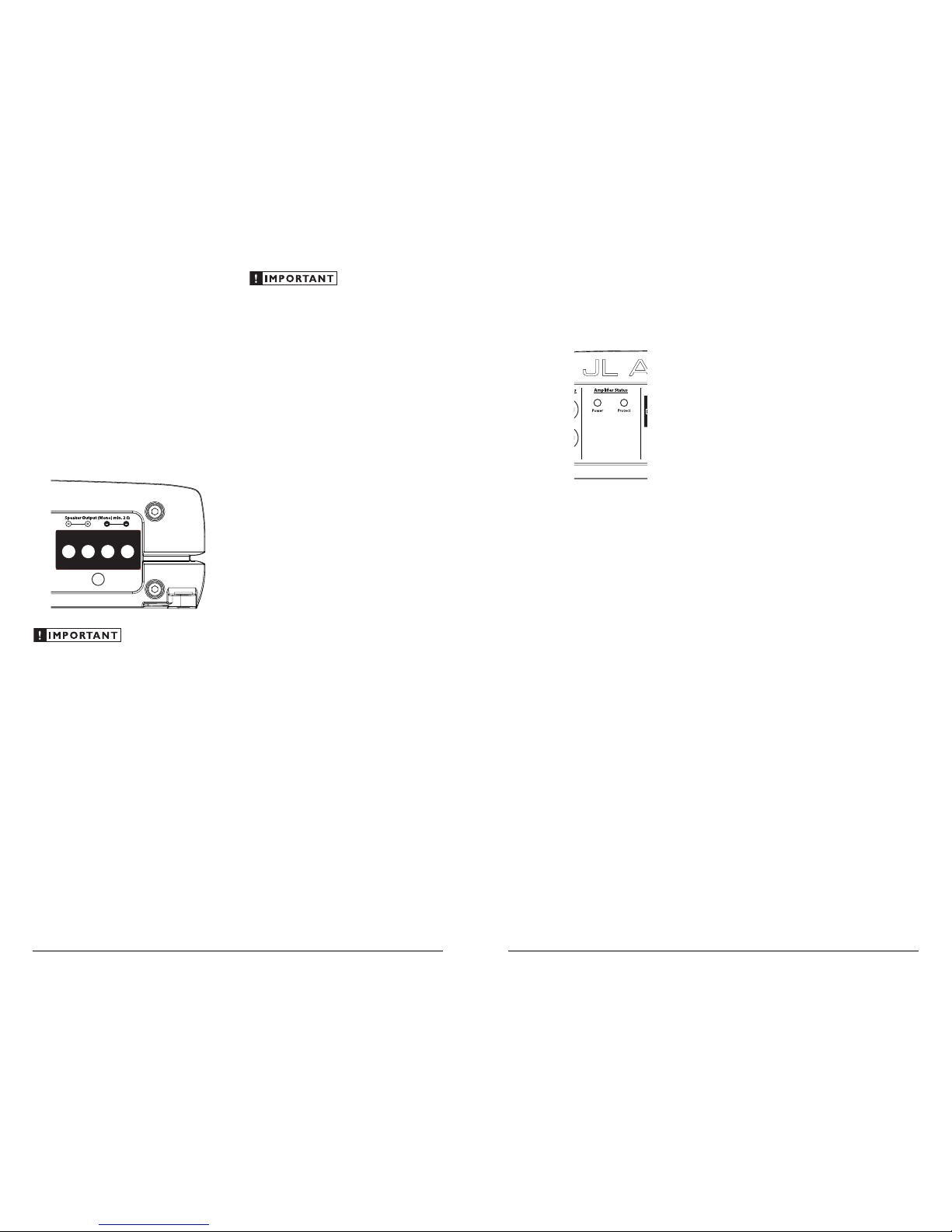
AMPLIFIER STATUS INDICATOR LIGHTS &
PROTECTION CIRCUITRY
There are two status i ndicator lights on the
input / control end of t he amplifier.
1) “P ower ” (Gre en): lights to indicate that the
amplif ier is turned on and operat ing norma lly.
2) “Prot ect” (Red): I ndicates that the ampl ifier
protection circuitry has be en activ ated to
prevent product failure due to a shor t-circuit
or a dangerously low impedance connected
to the ampli fier output(s). Connecting the
speaker out puts to an impedance lower t han
2 ohms stereo (4 ohms bridged) will cause
this protec tion mode to activate. When this
protection mode is activated, the a mplifier will
reduce it max imum power output to protect its
circuitry, which will manifest itself as increased
distort ion. When the problem is corrected, the
amplifier will return to normal operation.
Advanced Rol lback Thermal protec tion
Unlike conventional thermal protection
systems, which shut down an amplifier when it
overheats, this system protects the amplifier by
gradually reducing power output if t he amplif ier’s
safe operating temperature is exceeded. The
amplif ier will continue to operate and return
to normal power out put once its temperature
returns to a normal range.
Low-Voltage protection:
If the car’s supply voltage drops below 10
volts, the entire amplifier will shut itself off to
protect its internal circuitry. The green “ Power”
indicator w ill turn off when this occurs. The
amplif ier will turn back on when voltage cl imbs
back above 10 volts. This may happen in a rapid
cycle when bass-heavy program material c auses
a weak charging sy stem to dip below 10 volts
momentarily. If this is happening in your system,
turn your audio system off and have your power
wiring, ground connect ions and cha rging
system inspected.
SERVICING YOUR JL AUDIO AMPLIFIER
If your amplifier fails or malfunctions, please
return it to your authorized JL Audio dealer so
that it may be sent in to JL Audio for service.
There are no user serv iceable par ts or fuses inside
the ampli fier. The unique nature of t he circuitry
in the JL Audio amplifiers requires specifically
trained serv ice personnel. Do not attempt
to service the amplifier you rself or through
unauthori zed repair facil ities. This will not only
void the warranty, but may resu lt in the creation
of more problems within the amplifier.
If you have any quest ions about the instal lation or
setup of the a mplifier not covered in t his manual,
please contac t your dealer or technical support .
JL Audio Technical Support:
(954) 4 43-1100
9:00 AM – 5:30 PM (Eastern Time Zone)
Monday - Friday
JL AUDIO A1200 11
SPEAKER OUTPUTS
The A1200’s spea ker outputs are designed to
accept 8 AWG - 16 AWG wire.
The A1200 is designed to deliver power into
speaker loads equa l to or greater t han 2 ohms.
To connect the spea ker wires to the ampli fier,
first back out the set screws own t he top of the
termina l block, using the supplied 2 .5 mm hex
wrench. St rip 1/2 inch (12 mm) of insu lation from
the end of each w ire and insert the bare wire i nto
the termi nal block, seating it f irmly so that no
bare wire is exposed . While holding the wi re in
place, tig hten the set screw fir mly, taking care not
to strip the head of the screw.
Speaker loads below 2 ohms nomi nal are not
recommended and may cause the a mplifier
to initiate a protection mode which reduces
power output.
You will notice t hat there are two “+” positive
connections and two “–” negative connections.
This is to facilitate multiple speaker w iring.
The two positive and two negative connections
are connected in par allel i nside the amplifier.
Connect ing two speakers, each to one set of
positive and negative terminals, will result in a
paral lel speaker connection. If only connect ing
one pair of speaker wi res, it is not nece ssar y to
use both sets of connections.
Do not attempt to “bridge” the outputs of this
amplifier with the outputs of a second amplifier,
including an identical one.
10 JL AUDIO A1200

APPENDIX B:
Precise Frequency Selection Chart
“FILTER FREQ” AMP FILTER
Detent Panel Actual
Number Marking Freq.
Full counter-clockwise: 53
01 . . . . . . . . . . . . . . . . . . . . . . . . . . . .53
02 . . . . . . . . . . . “50”. . . . . . . . . . . .53
03 . . . . . . . . . . . . . . . . . . . . . . . . . . . .53
04 . . . . . . . . . . . . . . . . . . . . . . . . . . . .54
05 . . . . . . . . . . . . . . . . . . . . . . . . . . . .54
06 . . . . . . . . . . . . . . . . . . . . . . . . . . . .55
07 . . . . . . . . . . . . . . . . . . . . . . . . . . . .55
08 . . . . . . . . . . . “55”. . . . . . . . . . . .56
09 . . . . . . . . . . . . . . . . . . . . . . . . . . . .56
10 . . . . . . . . . . . . . . . . . . . . . . . . . . . .57
11 . . . . . . . . . . . . . . . . . . . . . . . . . . . .58
12 . . . . . . . . . . . . . . . . . . . . . . . . . . . .59
13 . . . . . . . . . . . . . . . . . . . . . . . . . . . .62
14 . . . . . . . . . . . “60”. . . . . . . . . . . .65
15 . . . . . . . . . . . . . . . . . . . . . . . . . . . .65
16 . . . . . . . . . . . . . . . . . . . . . . . . . . . .66
17 . . . . . . . . . . . . . . . . . . . . . . . . . . . .70
18 . . . . . . . . . . . . . . . . . . . . . . . . . . . .73
19 . . . . . . . . . . . . . . . . . . . . . . . . . . . .77
20 . . . . . . . . . . . “80”. . . . . . . . . . . .81
21 . . . . . . . . . . . . . . . . . . . . . . . . . . . .84
22 . . . . . . . . . . . . . . . . . . . . . . . . . . . .88
23 . . . . . . . . . . . . . . . . . . . . . . . . . . . .94
24 . . . . . . . . . . . . . . . . . . . . . . . . . . .101
25 . . . . . . . . . . . . . . . . . . . . . . . . . . .104
26 . . . . . . . . . . “120” . . . . . . . . . . 115
27 . . . . . . . . . . . . . . . . . . . . . . . . . . .118
28 . . . . . . . . . . . . . . . . . . . . . . . . . . .128
29 . . . . . . . . . . . . . . . . . . . . . . . . . . .137
30 . . . . . . . . . . . . . . . . . . . . . . . . . . .146
31 . . . . . . . . . . . . . . . . . . . . . . . . . . .164
32 . . . . . . . . . . “150” . . . . . . . . . . 177
33 . . . . . . . . . . . . . . . . . . . . . . . . . . .193
34 . . . . . . . . . . . . . . . . . . . . . . . . . . .197
35 . . . . . . . . . . . . . . . . . . . . . . . . . . .209
36 . . . . . . . . . . . . . . . . . . . . . . . . . . .213
37 . . . . . . . . . . . . . . . . . . . . . . . . . . .216
38 . . . . . . . . . . “200” . . . . . . . . . . 218
39 . . . . . . . . . . . . . . . . . . . . . . . . . . .225
Full-clockwise: 225
JL AUDIO A1200 13
APPENDIX C:
A1200 Specifications
General Specifications:
Recommended Fuse Value: 25A
Recommended Fuse Type: AGU, AFS or MaxiFuse™
Input Sections:
No. of Inputs: One Stereo Pair
Input Type: Differential-balanced with RCA jack inputs
Input Range: Switchable from 200mV - 2V RMS to
800mV - 8V RMS
Amplifier Section:
Amplifier Topology: Class A/B with patented Absolute
Symmetry™ dual N-Channel MOSFET output design
Power Supply: Unregulated MOSFET switching type
Rated Power at 12.5 V with less than
0.08% THD+Noise (20Hz - 2 kHz):
120W RMS x 1 @ 4 ohms, 200W RMS x 1 @ 2 ohms
Rated Power @ 14.4V with less than
1% THD + Noise (20Hz - 20 kHz):
175W RMS x 1 @ 4 ohms, 275W RMS x 1 @ 2 ohms
Signal to Noise Ratio: >104 dB referred to rated power
(A-weighted, 20 Hz-20 kHz noise bandwidth)
Frequency Response: 10 Hz - 25 kHz (+0, -1dB)
Damping Factor: >200 @ 4 ohms/50 Hz,
>100 @ 2 ohms/50 Hz
Slew Rate: ± 22V/µs
Amplifier Filter:
Filter Type: State-variable, 12dB/octave Butterworth with
continuously variable cutoff frequency selection from
50-200 Hz. Configurable as Low-Pass or High-Pass.
Defeatable.
Preamp Output:
Buffered pass-through type.
Dimensions(LxWxH):
9.8" x 9.25" x 2.50" (250mm x 235mm x 63.5mm)
12 JL AUDIO A1200
APPENDIX A:
Input Sensitivity Level Setting
Following t he directions below wi ll allow the
installer to adjust t he input sensitivity of each
amplif ier channel pair simply and easily in just a
few minutes using equipment which is commonly
available in installation bays.
Necessary Equipment
• Digital AC Voltmeter
• CD with a sine-wave test tone recorded at
0 dB reference level in the frequency range
to be amplif ied for that set of channel s
(50 Hz for subwoofer chan nels, 1 kHz for a
midrange appl ication). Do not use attenuated
test tones (-10 dB, -20 dB, etc.).
The Nine-St ep Procedure
1) Disconnect the speaker(s) from the
amplif ier’s speaker out put connectors.
2) Turn off all processing ( bass/treble, loudness,
EQ, etc.) on the sou rce unit, processors (if
used) and amplifier. Set fader cont rol to center
position and subwoofer level cont rol to 3/4 of
maxi mum (if used to fe ed the A120 0).
3) Switch the “Input Voltage” switch to “Low”
and turn the “Input Sens.” control all the
way down.
4) Set the source unit volume to 3/4 of full
volume. This will a llow for reasonable gain
overlap with moderate clipping at full volume.
5) Using the c hart on this page , determine the ta rget
voltage for input sen sitivity adjustment a ccording
to the nomin al impedance of th e speaker system
connected t o the amplifier out puts.
6) Verify that you have disconnected the speakers
before proceed ing. Play a track wit h an
appropriate sine wave (within t he frequency
range to be amplified by the A1200) at 3/4
source unit volume.
7) Connect t he AC voltmeter to the speaker output
connectors of the amplifier. Make sure you test
the voltage at t he correct connectors (+ and –).
8) Increase the “Input Sens.” control unt il the
target voltage is observed with the voltmeter.
9) Once you have adjusted the A1200 to its
maximum low-distor tion output level,
reconnect t he speaker(s). The “Input Sens.”
controls can now be adjusted downward if the
amplifier requires at tenuation to achieve the
desired system balance.
Do not increase any “Input Sens.” setting for
any amplifier channel or channel pair in the
system beyond t he maximum level establ ished
during this procedure. Doing so will result in
audible distortion and possible speaker da mage.
It will be necessary to re-adjust the
“Input Sens.” for the affected chan nels if any
equalizer boost is activated af ter setting the
“Input Sens.” with this procedure. This applies
to any EQ boost circuit, including source unit
tone controls or EQ circuits. EQ cuts will not
require re-adjustment.
Nom. Impedance Target AC Voltage
4 21.9 V
3 21.0 V
2 20.0 V
Due to ongoing product development, all specifications are subject to
change without notice.

JL AUDIO A1200 15
“My amplif ier shuts off once i n a while, usually at hig her volumes”
Check your voltage source and grounding point. The power supply
of the A1200 w ill operate with charging system voltages
down to 10V. Shutdown problems at higher volume levels
can occur when the charging system voltage drops below
10V. These dips can be of very short duration making them
extremely diff icult to detect wit h a common DC voltmeter.
To ensure proper voltage, inspect all wiring and termination
points. It may also be necessary to upgrade t he ground
wire connecting the battery to the vehicle’s chassis and the
power wire con necting the alternator to the battery. Many
vehicles employ sma ll (10 AWG - 6 AWG) w ire to ground the
battery to the vehicle’s chassis and to c onnect the alternator to
the batter y. To prevent voltage drops, the se wires should be
upgraded to 4 AWG when insta lling amplif ier systems with
main fuse rati ngs above 60A. Ground ing problems are t he
leading cause of misd iagnosed amplif ier “failures.”
“My amplif ier turns on, but the re is no output”
Check the input signal using an AC voltmeter to measure the
voltage from the source un it while a n appropriate test tone is
played through the source unit (discon nect the input cables
from the amplifier prior to this test). The frequency used
should be in the range that is to be amplified by the amplifier
(example: 50 Hz for a sub ba ss application or 1 kHz for a fu ll
range / hig h-pass applic ation). A steady, suff icient voltage
(between 0.2 and 8.0-volts) should be present at the output of
the signal cables.
Check the output of the amplif ier. Using the procedure expla ined in
the previous check item (after plugging the input cables back
into the ampl ifier) test for output at the spea ker outputs of
the ampli fier. Unless you enjoy test tones at high levels, it is
a good idea to remove the speaker w ires from the amplifier
while doing this. Turn the volume up approximately ha lf
way. 5V or more should be measured at the speaker outputs.
This output level can va ry greatly between amplifiers but it
should not be in the millivolt range with the source unit at
half volume. If you are read ing sufficient volta ge, check your
speaker connections as expla ined below.
Check to ensure that t he speaker wires are maki ng a good
connection with the metal inside the terminal block. The
speaker wire connectors are designed to accept up to 8 AWG
wire. Ma ke sure to strip the wi re to allow for a sufficient
connection with the metal inside the terminal block.
“How do I prop erly set the input sen sitivity on my ampli fier”
Please refer to Appendi x A (page 12) to set the input sensitiv ity for
maximum, low-distor tion output.
“My amplif ier doesn’t turn on”
Check the fuse, not just visually, but with a conti nuity meter. It is
possible for a fuse to have poor internal con nections that
cannot be found by visual inspection. It is best to take the
fuse out of the holder for testi ng. If no problem is found with
the fuse, inspect the fu se-holder.
Check the integ rity of t he connect ions made to each of the
“+12V DC ”, “Ground”, and “Remote” terminals. Ensure
that no wire insulation is pinched by the terminal set screw
and that each connection is tight.
Check to make sure there is +12V at the “Remote” connection of t he
amplifier. In some cases, the turn-on lead from the source unit
is insuf ficient to turn on multiple devic es and the use of a relay
is required. To test for this problem, ju mp the “+12V DC ” wire
to the “Remote” termi nal to see if the ampl ifier turns on. I f this
does not work, proce ed to the next step.
“I get a disto rted / attenuated s ound coming out of the sp eaker(s)”
Check the spea ker wires for a possible shor t, either between the
positive and negative leads or between either spea ker lead
and the vehicle’s chassis ground. If a shor t is present, you
will experience distorted and/or attenuated output. The
“Protect” light will illuminate in this situation. It may be
helpful to disconnec t the spea ker wires from the amplifier
and use a di fferent set of wires connected to a test speaker.
Check the nomina l load impedance to veri fy that of the amplifier is
drivi ng a load equal to or greater t han 2 ohms .
Check the input signal and input signal cables to make sure signa l
is present at the “A mp lif ie r In put s” and the cables a re not
pinched or loose. It may be helpful to t ry a different set of
cables and/or a different sig nal source to be sure.
“My amplif ier’s output fluc tuates when I tap on it or hi t a bump”
Check the connections to the amplifier. Make sure that the
insulat ion for all wires has been stripped back far enou gh to
allow a good contact area inside the termina l block.
Check the input connectors to ensure that they all are making good
contact with the input jacks on the amplif ier.
14 JL AUDIO A1200
APPENDIX D: TROUBLE SHOOTING

JL AUDIO A1200 17
16 JL AUDIO A1200
INSTALLATION NOTES:
Use this diagram to document your amplifier’s switch and control positions.

JL AUDIO A1200 19
18 JL AUDIO A1200
INSTALLATION NOTES: INSTALLATION NOTES:

LIMITED WARRANTY AMPLIFIERS USA
JL AUDIO warrants this product to be free of defects in materials and workmanship for a period of
ninety (90) days from the original date of purchase. The warranty term is extended to two (2) years if
installation is performed or approved by an authorized JL AUDIO dealer (proof of installation or approval
required on purchase receipt).
This warranty is not transferrable and applies only to the original purchaser from an authorized
JL AUDIO dealer. Should service be necessary under this warranty for any reason due to manufacturing
defect or malfunction, JL AUDIO will (at its discretion), repair or replace the defective product with new
or remanufactured product at no charge. Damage caused by the following is not covered under warranty:
accident, misuse, abuse, product modification or neglect, failure to follow installation instructions,
unauthorized repair attempts, misrepresentations by the seller. This warranty does not cover incidental
or consequential damages and does not cover the cost of removing or reinstalling the unit(s). Cosmetic
damage due to accident or normal wear and tear is not covered under warranty.
Warranty is void if the product’s serial number has been removed or defaced.
Any applicable implied warranties are limited in duration to the period of the express warranty as
provided herein beginning with the date of the original purchase at retail, and no warranties, whether
express or implied, shall apply to this product thereafter. Some states do not allow limitations on implied
warranties, therefore these exclusions may not apply to you. This warranty gives you specific legal rights,
and you may also have other rights which vary from state to state.
If you need service on your JL AUDIO product:
All warranty returns should be sent to JL AUDIO ’s Amplifier Service Facility freight-prepaid through
an authorized JL AUDIO dealer and must be accompanied by proof of purchase (a copy of the original
sales receipt). Direct returns from consumers or non-authorized dealers will be refused unless specifically
authorized by JL AUDIO with a valid return authorization number.
Warranty expiration on products returned without proof of purchase will be determined from the
manufacturing date code. Coverage may be invalidated as this date is previous to purchase date. Nondefective items received will be returned freight-collect. Customer is responsible for shipping charges and
insurance in sending the product to JL AUDIO. Freight damage on returns is not covered under warranty.
For Service Information in the U.S.A. please call
JL Audio Customer Service: (954) 443-1100
9:00 AM – 5:30 PM (Eastern Time Zone)
JL Audio, Inc
10369 North Commerce Pkwy.
Miramar, FL 33025
(do not send product for repair to this address)
International Warranties:
Products purchased outside the United States of America are covered only
by that country’s distributor and not by JL Audio, Inc.
A1200MAN-04-2006
Absolute Symmetry™ Class A/B Amplifier Circuit is covered by U.S. Patent #6,294,959 and is pending in the
countries listed below.
Austria, Belgium, Brazil, Canada, China, France, Germany, Indonesia, Italy, Japan, Republic of Korea,
Mexico, Netherlands, Norway, Russian Federation, Singapore, Sweden, Switzerland, United Kingdom, and all other PCT countries.
 Loading...