


OWNER’S MANUAL
6.50-inch (165 mm) 2-Way Component System
Thank you for choosing JL Audio loudspeakers for your automotive sound system.
We strongly recommend that you have your new loudspeakers installed by an authorized JL Audio dealer. Your authorized dealer has the training, expertise and installation equipment to ensure
optimum performance of these loudspeakers in your vehicle.
If you decide to install the loudspeakers yourself, please read this manual thoroughly to familiarize yourself with their installation
requirements and setup procedures.
Should you have any questions regarding the instructions in this manual, please contact your authorized JL Audio dealer for assistance, or call the JL Audio Technical Support Department at (954) 443-1100
during business hours (USA - Eastern Time Zone).

B |
A |
D |
|
|
|
|
|
C |
Woofer Physical Dimensions
Frame Outer Diameter (A) |
6.25 in. / 159 mm |
Mounting Hole Diameter (B) |
5.02 in. / 128 mm |
Motor Outer Diameter (C) |
3.15 in. / 80 mm |
Mounting Depth - speaker only (D) |
2.07 in. / 53 mm |
Mounting Depth - with ring |
1.79 in. / 45 mm |
A |
D |
|
|
||
C |
D |
|
A |
||
|
||
B |
|
Tweeter Fixture Physical Dimensions |
Flush-Mount |
Surface-Mount |
Fixture Outer Diameter (A) |
1.67 in. / 42 mm |
1.71 in. / 43 mm |
Fixture Mounting Hole Diameter (B) |
1.46 in. / 37 mm |
N/A |
Fixture Mounting Depth (C) |
0.40 in. / 10 mm |
N/A |
Tweeter Frontal Protrusion (D) |
0.23 in. / 6 mm |
0.76 in. / 19 mm |
|
B |
|
|
C |
|
|
A |
|
Crossover Network Physical Dimensions |
|
|
Width (A) |
1.96 in. / 50 mm |
|
Height (B) |
0.90 in. / 23 mm |
|
Depth (C) |
1.34 in. / 34 mm |
|
Due to ongoing product development, all specifications are subject to change without notice.
2 | JL Audio - C1-650 Owner’s Manual

C1-650 SPECIFICATIONS:
Continuous Power Handling: 50 Watts
Recommended Amp Power: 10-75 Watts per channel (RMS) Efficiency: 90.5 dB @ 1W / 1m | 96.5 dB @ 1W / 0.5m Sensitivity: 93.0 dB @ 2.83V / 1m
Nominal Impedance: 4 ohm
Frequency Response: 48 Hz - 24 KHz ± 3 dB
Woofer:
Injection-molded, mineral-filled, polypropylene cone Rubber, positive roll surround
1.0 in. (25 mm) diameter voice coil
Flat, Conex® spider with integrated lead wires Ferrite Magnet
Tweeter:
Edge-driven, silk-suspended aluminum dome 0.75 in. (19 mm) diameter diaphragm / voice coil Ferrofluid cooling / damping
Neodymium magnet
Crossover:
Natural roll-off, low-pass
2nd order, high-pass filter with inductor and electrolytic capacitor
Included Components and Parts:
•Two (2) C1-650cw 6.50-inch (165 mm) woofers
•Two (2) C1-075ct 0.75-inch (19 mm) tweeters
•Two (2) surface-mount tweeter fixtures
•Two (2) C1-075cthp in-line, high-pass filters on 4 ft. (1.2 m) wire harnesses
•Two (2) metal spring clips (for tweeter flush-mounting)
•Eight (8) #8 x 0.75-inch (19mm) sheet metal screws
•Eight (8) #8 x 0.25-inch (6mm) thread forming screws
•Four (4) #6 x .625-inch (22 mm) sheet metal screws
•Eight (8) mounting clips
•Two (2) 4.7 mm female crimpable connectors
•Two (2) 2.8 mm female crimpable connectors
•Two (2) 10mm stud bolts with fixed M4 nut
•Two (2) 25mm stud bolts with fixed M4 nut
•Two (2) M5 nuts
•Two (2) multi-application speaker adaptor rings
GETTING STARTED
•Turn off the audio system. It is also advisable to disconnect the negative (–) terminal of your vehicle’s battery whenever performing installation work.
•Before cutting, drilling or inserting any screw, check clearances on both sides of the planned mounting surface. Also check for any potential obstacles, such as window tracks and motors, wiring harnesses, etc. Check both sides of the vehicle, many vehicles are not symmetrical!
•Always wear protective eyewear.
SPEAKER PLACEMENT CONSIDERATIONS
Grilles are not included with C1 speakers, as they are designed for installation into OEM (factory) speaker locations, located behind factory grilles. Should you need grilles, you will need to purchase aftermarket grilles separately.
!!  WA R N I N G
Prolonged exposure to sound pressure levels in excess of 100dB can cause permanent hearing loss. These high-performance loudspeakers can exceed this level. Please exercise restraint in their operation in order to preserve your ability to enjoy their fidelity.
Due to ongoing product development, all specifications are subject to change without notice.
3
SPEAKER PLACEMENT CONSIDERATIONS
A component system gives you the ability to place the woofer and tweeter separately in your vehicle interior. This can be good or bad, depending on how it’s done. As a general rule, the tweeters should be placed relatively close to the woofers for best tonal balance and most coherent imaging (the closer, the better). Any separation greater than 8 inches (20 cm) is likely to result in degraded sound quality.
Avoid placing tweeters where they will be blocked by objects in the interior of the car (including seated occupants). When selecting a mounting location, look at both sides of the car to make sure that this location is clear on both sides.
You can always experiment with tweeter placement before committing to a final mounting location. Simply connect the rest of the system and allow plenty of wire length for the tweeters. Using hook and loop or similar material, attach the tweeters in different locations until you find the one where they perform best.
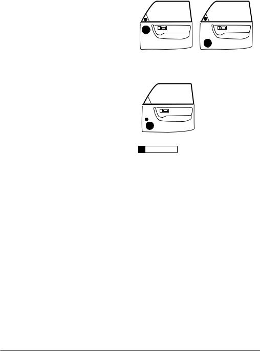
Woofers will usually be placed into factory speaker locations. If you have some woofer mounting flexibility, keep the following in mind: Lower mounting locations, such as the lower front corner of a door or a kick-panel provide the greatest path length distances for the sound emitted by the woofer. For this reason, they are generally more desirable than higher mounting locations. Higher mounting locations often result in extreme nearside soundstage bias which compromises the stereo listening experience.
DIAGRAM A:
Less Desirable Speaker Placement
DIAGRAM B:
More Desirable Speaker Placement
!!  WA R N I N G
Double check the clearance for both speakers before proceeding. Many cars are different from one side to the other!
4 | JL Audio - C1-650 Owner’s Manual
 Loading...