

JL Audio ACP1 08LG-W3v3, ACP208LG-W3v3, ACP11 OLG-TW1, ACP112LG-TW1, ACS112LG-TW1 Owner's Manual
...
OWNER'S
@ @
~====~
MANUAL
@
@
MicroSub+
Amplified Subwoofer Systems
purchasing
for
you
Thank
your
subwoofer
Your
standards
musical
highly
an
by
necessary
optimum
subwoofer
your
thoroughly
system
provide
to
enjoyment
recommend
authorized
training,
pe~formance
in
that
JL
expertise
system
familiarize
to
as
so
I
JL
a
automotive
been
has
high-quality
vehicle.
your
have
you
retailer.
Audio
and
this
from
yourself,
please
yourself
@
@
PowerVVedge+
Amplifier Technology
DCD™
with
woofer
amplified
Audio
sound
designed
sub-bass
For
new
your
Your
installation
product.
take
with
sub
system.
manufactured
and
performance
maximum
subwoofer
authorized
equipment
you
Should
time
the
installation
it
performance,
system
retailer
decide
read
to
for
system
exacting
to
of
years
and
we
installed
the
has
ensure
to
install
to
manual
this
requirements
Ifyou
manual
your
assistance,
have
aspect
any
or
authorized
please
(954)
questions
any
of
Audio
JL
call
443-1100
and
your
JL
the
retailer
procedures.
setup
regarding
subwoofer
for
Technical
Audio
during
instructions
the
system's
operation,
assistance.
Support
business
hours.
need
you
If
Department
this
in
please
further
contact
at

SAFETY
CONSIDERATIONS
Install this subwoofer system in a
•
does not interfere
ventilated location
that
dry, well-
with your vehicle's safety equipment (air bags,
brake systems, etc.).
seat belt systems,
Securely mount the subwoofer system so
•
that it does not come loose in the event
ABS
of
a collision or a sudden jolt to the vehicle.
Check before drilling to make sure that you
•
will not be drilling into a gas tank, brake line,
other vital vehicle system.
wiring harness
Do not
•
run
underneath the vehicle. This
or
system wiring outside or
an
is
extremely dangerous practice, which
can result in severe damage/injury.
• Protect
carefully routing them, tying them down
using grommets
Secure all wiring as needed, using cable
•
all system wires from sharp edges by
and
loom where appropriate.
and
ties or wire clamps to protect them
sharp edges.
from moving parts
WHAT'S
(1)
in
(1)
(1)
(1)
(1)
PRODUCT DESCRIPTION
INCLUDED
Enclosure with subwoofer(s), built-
amplifier and grille(s)
""
DCD
Connection plug
Power
High-Level input plug
Fuse
manual
User
and
Enclosed subwoofer system with built-
Class D amplifier and specially
'""'
DCD
in
engineered, low-impedance driver(s).
TECHNOLOGY
ABOUT
DCD™
Audio's exclusive DCD
JL
amplifier technology
'""
combines direct power conversion with an ultrahigh current output section and unique lowimpedance drivers to extract maximum power
directly converting a vehicle's
efficiency.
supply into speaker power,
free
By
amplifiers are
'""
DCD
traditional switching power supplies, thus
of
and
12V
enabling them to be very compact, while generating
remarkable power output with unprecedented
'"
efficiency (up to
. This also permits
94%)
DCD
amplifiers to operate at much cooler temperatures
than conventional amplifiers.
WARNING!
DCD""
amplified
subwoofer
systems use very specific components. Never
companion
its
DCD"' amplifier
use a
subwoofer(s) with incompatible,
products. Doing so will void
may cause severe damage/injury.
and
or
non-DCDTM
warranty
the
INSTALLATION APPLICATIONS
The built-in amplifier used in this subwoofer
designed for operation in vehicles
system
with
Using
ground and/or voltages other
may result in damage to the product
will void the warranty. This product
certified
INSTALLATION PROCEDURE/CONNECTIONS
is
negative-ground electrical systems.
12V,
this product in systems with positive
12V
than
and
not
is
approved for use in aircraft.
or
All connections are located on the amplifier
the enclosure. All connections are made
of
panel
via RCA-type or quick-disconnect plugs, making it
easy to remove the enclosure quickly, anytime you
need additional space in your vehicle.
Disconnect the NEGATIVE battery post
1.
secure the disconnected
connection
and
cable to prevent accidental reconnection
during installation.
precaution
safety
Run power wire from the battery location to
2.
the amplifier's
care to route
damaged
and
operation. 8 A WG is
This
installation!
connection, taking
VDC"
"+
12
during
it in such a way that it will not be
will not interfere with vehicle
recommended
the
essential
an
is
power wire size for this amplifier.
An appropriate fuse at the main power
3.
vital for vehicle
wire to the amplifier
safety. This fuse must be installed within
ctn)
(45
inches
post connection.
connected to this
is
the positive
of
this
If
main
(+12V)
the only device
is
wire, use a
30A
18
battery
fuse.
Do not install the fuse until the power wire
has been securely connected to the amplifier.
Find a good, solid metal grounding point
4.
connect the
close to the amplifier panel
and
negative power wire to it using appropriate
the same sized wire used
hardware.
for the
inches
Use
longer than
connection,
+12V
em) from the amplifier's ground
(90
no
36
(GND) connector to the ground connection
recommended
point. 8 AWG is
ground
Run a wire from the source unit's positive
5.
( +
wire size for this amplifier.
remote
12V)
amplifier's
the
turn-on
"Remote"
output to the
connection.
If
your
source unit does not have a dedicated remote
turn-on output, you may elect to use one
the automatic
the amplifier's
"Control Panel
turn-on
"Turn-On Mode"
Settings and Adjustments.")
6. Signal Input (Lowamp) ifier's
RCA
unit's preamp level output jacks.
a stereo or a mono signal into the
run
options, configured via
switch.
Connect the
Level):
input jacks to the source
You
of
(See
may
2
~L
AUDIO
'P
the amplifier. The amplifier's
of
inputs
input section automatically sums stereo
signals to mono for the internal amplifier
section. When feeding a single, low-level
RCA input connection, use a Y-adaptor
splitter to split the mono signal and connect
inputs.
RCA
Right
and
Left
both
to
it
your system
Signal Input (High-Level):
7.
If
does not offer a preamp level signal option,
you can connect speaker level signals directly
to the ((High-Level
Inputs"
the supplied 4-pin plug
connector using
wire harness.
and
Simply splice the appropriate left/right
and positive/negative wires to the included
harness, and plug the harness into the ((High-
the amplifier. The
Level
Inputs"
connector
on
amplifier will attenuate the high-level signal
compatible with its input stage.
to make
it
Refer to the table below for corresponding
wire color information. Make sure to observe
correct polarity in making high-level input
connections. Failure to do so will result
signal (poor performance).
in a loss
Make necessary adjustments to the
8.
input sensitivity
With the optional
9.
of
filter controls.
and
RBC-1
Remote
Level
Control (sold separately), you can control
the amplifier's output level from the
front
the veh ide. Connect the
of
RBC-1
to the amplifier's panel-mounted RJll
input jack. (Refer to Appendix
B)
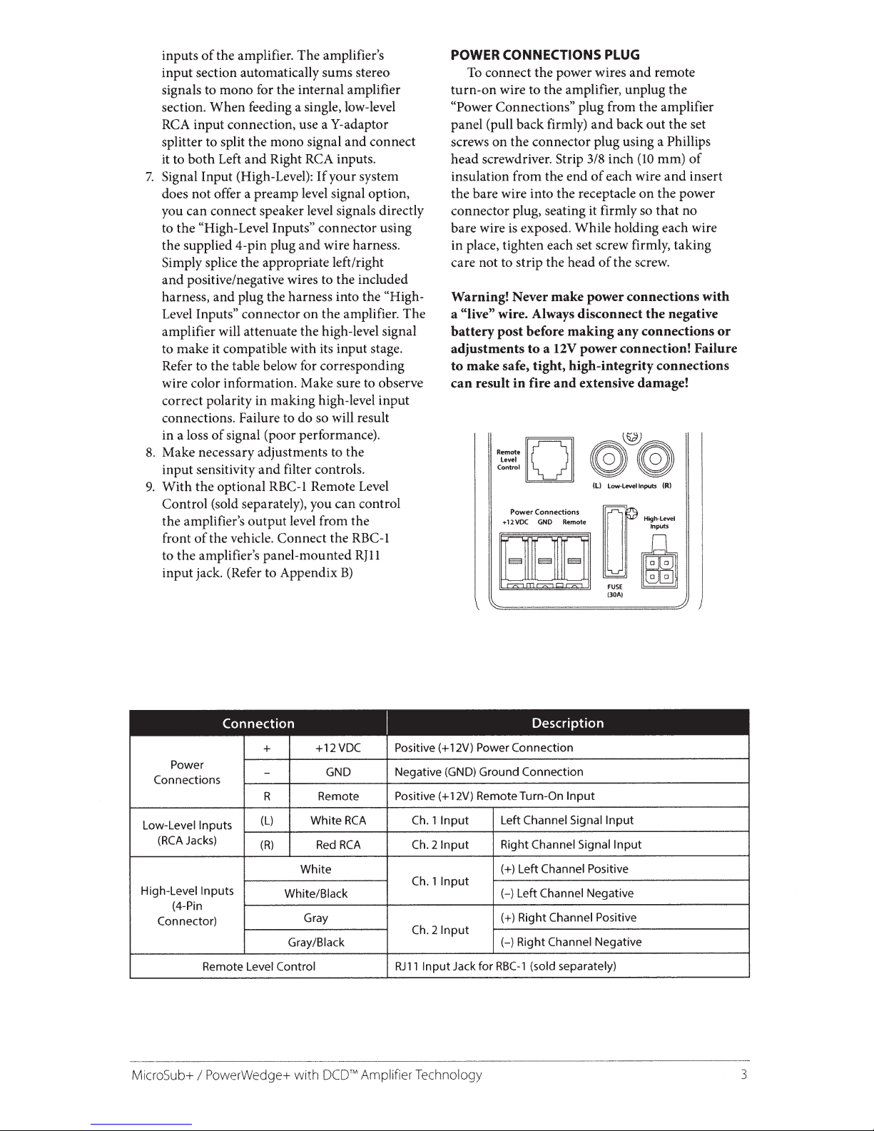
POWER CONNECTIONS PLUG
connect the power wires and remote
To
turn-on
((Power
panel (pull back firmly)
wire to the amplifier, unplug the
Connections" plug from the amplifier
back out the set
and
screws on the connector plug using a Phillips
3/8 inch
head screwdriver.
insulation from the end
Strip
of
the bare wire into the receptacle
(10
each wire
on
insert
and
the power
of
mm)
connector plug, seating it firmly so that no
exposed. While holding each wire
bare wire
is
in place, tighten each set screw firmly, taking
the screw.
care not to strip the head
Warning! Never
"live" wire. Always disconnect
a
battery
post
adjustments
safe,
make
to
result
can
Remote
Level
Control
+ 12
make
before
12V
a
to
tight,
and
fire
in
[Q]
Connections
Power
GND Remote
VDC
of
power connections
negative
the
connections
making
any
power connection! Failure
high-integrity connections
extensive damage!
Low-Levellnputs
(L)
rr·
(R)
Ht'~:::el
[IJ[]i
~FUSE
(30A)
m
with
or
+
Power
Connections
R Remote
Low-Level
High-Level
MicroSub+
Inputs
Jacks)
(RCA
Inputs
(4-Pin
Connector)
Remote Level
PowerWedge+ with
I
(L)
(R)
White/Black
Gray/Black
Control
+12VDC
GND Negative
RCA
White
RCA
Red
White
Gray
Amplifier Technology
DCDTM
Positive(+
Positive(+
Input
1
Ch.
21nput
Ch.
Input
1
Ch.
21nput
Ch.
Input
RJll
Connection
Power
12V)
Ground Connection
(GND)
12V) Remote Turn-On
Channel Signal
Left
Channel Signal
Right
Channel Positive
(+)Left
Channel
(-)Left
(+)Right
{-)Right
(sold separately)
RBC-1
for
Jack
Input
Input
Input
Negative
Channel Positive
Channel
Negative
3
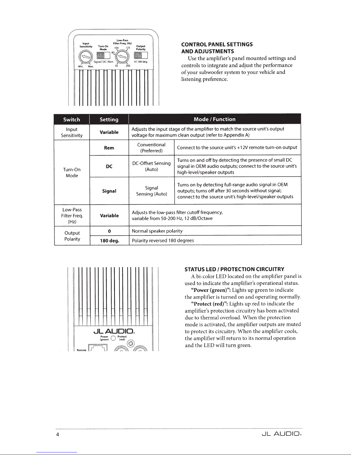
SSJ~l:S!~I
Min. Max.
Switch
Input
Sensitivity
Turn-On
Mode
Input Filter Freq.
I
low-Pass
50 200
Setting
Variable
Rem
DC
Signal
(Hz)
I
Adjusts the
voltage
Conventional
(Preferred)
-Offset
DC
Sensing (Auto)
input
for maximum
Sensing
(Auto)
Signal
CONTROL
ADJUSTMENTS
AND
the
Use
controls to integrate
your subwoofer system to your vehicle
of
listening preference.
Mode
amplifier
the
of
stage
output
clean
the source unit's
Connect
Turns on and
signal in
high-level/speaker
Turns on by detecting
outputs; turns
connect
to
OEM
the
to
PANEL
amplifier's panel
I
(refer
off
audio outputs; connect
off
source unit's
SETTINGS
mounted
adjust
and
Function
match the source unit's
to
Appendix
to
by detecting
outputs
full-range
30
after
A)
remote turn-on
12V
+
presence
the
audio
seconds
without
high-level/speaker
settings
performance
the
and
output
small
of
the source unit's
to
in
signal
signal;
outputs
and
output
DC
OEM
Low-Pass
Freq.
Filter
(Hz)
Output
Polarity
Variable
180
JLAUDID~
Power
(green) (red)
fll~ll
rr==;:ll
Remote
0
deg.
Q
Protect
~
Adjusts the low-pass
50-200Hz,
from
variable
speaker
Normal
reversed
Polarity
@
~
filter
polarity
degrees
180
frequency,
cutoff
dB/Octave
12
PROTECTION CIRCUITRY
STATUS LED
A hi-color LED located
used to indicate
"Power (green)":
the amplifier
"Protect (red)":
I
amplifier panel
the
on
amplifier's operational status.
the
Lights up green to indicate
operating normally.
and
on
turned
is
Lights up red to indicate
the
amplifier's protection circuitry has been activated
the protection
due to
thermal
overload.
mode is activated,
to protect its circuitry.
the amplifier will
the LED will
and
turn
When
amplifier outputs are muted
the
amplifier cools,
the
When
return
to its
normal
operation
green.
is
4
~L
AUDID
JlJ
 Loading...