

Page 1
OWNER’S MANUAL
50
80
125100
200
Low-Pass
Filter Freq. (Hz)
Turn-On
Mode
Remote
Level
Control
Low-Level Inputs
High-Level
Inputs
FUSE
(30A)
(L) (R)
Input
Sensitivity
Min. Max.
Signal | DC | Rem
0 | 180 deg.
+12 VDC GND Remote
Output
Polarity
Power Connections
Power
(green)
Protect
(red)
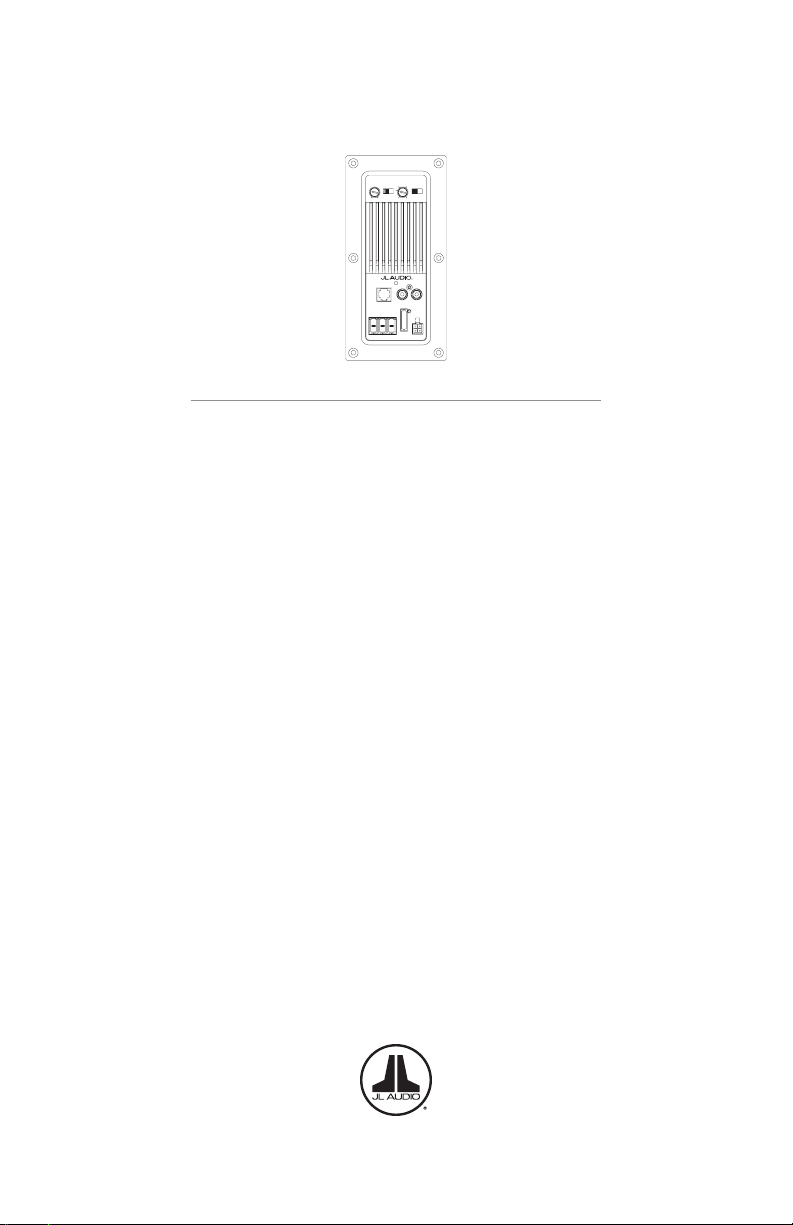
MicroSub+ / PowerWedge+
Amplied Subwoofer Systems with DCD™ Amplier Technology
Thank you for purchasing a JL Audio amplified subwoofer system for
your automotive sound system.
Your subwoofer system has been designed and manufactured to exacting
standards to provide high-quality sub-bass performance and years of
musical enjoyment in your vehicle. For maximum performance, we
highly recommend that you have your new subwoofer system installed
by an authorized JL Audio retailer. Your authorized retailer has the
necessary training, expertise and installation equipment to ensure
optimum performance from this product. Should you decide to install
your subwoofer system yourself, please take the time to read this manual
thoroughly so as to familiarize yourself with it installation requirements
and setup procedures.
If you have any questions regarding the instructions in this
manual or any aspect of your subwoofer system’s operation, please contact
your authorized JL Audio retailer for assistance. If you need further
assistance, please call the JL Audio Technical Support Department at
(954) 443-1100 during business hours.
Page 2

SAFETY CONSIDERATIONS
• Install this subwoofer system in a dry, wellventilated location that does not interfere
with your vehicle’s safety equipment (air bags,
seat belt systems, ABS brake systems, etc.).
• Securely mount the subwoofer system so
that it does not come loose in the event of
a collision or a sudden jolt to the vehicle.
• Check before drilling to make sure that you
will not be drilling into a gas tank, brake line,
wiring harness or other vital vehicle system.
• Do not run system wiring outside or
underneath the vehicle. This is an
extremely dangerous practice, which
can result in severe damage/injur y.
• Protect all system wires from sharp edges by
carefully routing them, tying them down and
using grommets and loom where appropriate.
• Secure all wiring as needed, using cable
ties or wire clamps to protect them
from moving parts and sharp edges.
WHAT’S INCLUDED
(1) Enclosure with subwoofer(s), builtin DCD™ amplifier and grille(s)
(1) Power Connection plug
(1) High-Level input plug
(1) F use
(1) User manual
PRODUCT DESCRIPTION
Enclosed subwoofer system with builtin DCD™ Class D amplifier and specially
engineered, low-impedance driver(s).
ABOUT DCD™ TECHNOLOGY
JL Audio’s exclusive DCD™ amplifier technology
combines direct power conversion with an ultrahigh current output section and unique lowimpedance drivers to extract maximum power and
efficiency. By directly converting a vehicle’s 12V
supply into speaker power, DCD™ amplifiers are
free of traditional switching power supplies, thus
enabling them to be very compact, while generating
remarkable power output with unprecedented
efficiency (up to 94%). This also permits DCD™
amplifiers to operate at much cooler temperatures
than conventional amplifiers.
WARNING! DCD™ amplified subwoofer
systems use very specific components. Never
use a DCD™ amplifier or its companion
subwoofer(s) with incompatible, non-DCD™
products. Doing so will void the warranty
and may cause severe damage/injury.
INSTALLATION APPLICATIONS
The built-in amplifier used in this subwoofer
system is designed for operation in vehicles
with 12V, negative-ground electrical systems.
Using this product in systems with positive
ground and/or voltages other than 12V
may result in damage to the product and
will void the warranty. This product is not
certified or approved for use in aircraft.
INSTALLATION PROCEDURE/CONNECTIONS
All connections are located on the amplifier
panel of the enclosure. All connections are made
via RCA-ty pe or quick-disconnect plugs, making it
easy to remove the enclosure quick ly, anytime you
need additional space in your vehicle.
1. Disconnect the NEGATIVE battery post
connection and secure the disconnected
cable to prevent accidental reconnection
during insta llation. This is an essential
safety precaution during installation!
2. Run power wire from the battery location to
the amplifier’s “+12 VDC” connection, taking
care to route it in such a way that it will not be
damaged and will not interfere with vehicle
operation. 8 AWG is the recommended
power wire size for this amplifier.
3. An appropriate fuse at the main power
wire to the amplifier is vital for vehicle
safety. This fuse must be installed within 18
inches (45 cm) of the positive (+12V) batter y
post connection. If this is the only device
connected to this main wire, use a 30A fuse.
Do not install the fuse until the power wire
has been securely connected to the amplifier.
4. Find a good, solid meta l grounding point
close to the amplifier panel and connect the
negative power wire to it using appropriate
hardware. Use the same sized wire used
for the +12V connection, no longer than 36
inches (90 cm) from the amplifier’s ground
(GND) connector to the ground connection
point. 8 AWG is the recommended
ground wire size for this amplifier.
5. Run a wire from the source unit’s positive
(+12V) remote turn-on output to the
amplifier’s “Remote” connection. If your
source unit does not have a dedicated remote
turn-on output, you may elect to use one of
the automatic turn-on options, configured via
the amplifier’s “Turn-On Mode” switch. (See
“Control Panel Settings and Adjustments.”)
6. Signal Input (Low-Level): Connect the
amplifier’s RCA input jacks to the source
unit’s preamp level output jacks. You may
run a stereo or a mono signal into the
2 JL AUDIO
®
Page 3
inputs of the amplifier. The amplifier’s
50
80
125100
200
Low-Pass
Filter Freq. (Hz)
Turn-On
Mode
Input
Sensitivity
Min. Max.
Signal | DC | Rem 0 | 180 deg.
Output
Polarity
Power
(green)
Protect
(red)
input section automatically sums stereo
signals to mono for the internal amplifier
section. When feeding a single, low-level
RCA input connection, use a Y-adaptor
splitter to split the mono signal and connect
it to both Left and Right RCA inputs.
7. Signal Input (High-Level): If your system
does not offer a preamp level signal option,
you can connect speaker level signals directly
to the “High-Level Inputs” connector using
the supplied 4-pin plug and wire harness.
Simply splice the appropriate left/right
and positive/negative wires to the included
harness, and plug the harness into the “HighLevel Inputs” connector on the amplifier. The
amplifier will attenuate the high-level signal
to make it compatible with its input stage.
Refer to the table below for corresponding
wire color information. Make sure to observe
correct polarity in making high-level input
connections. Failure to do so will result
in a loss of signal (poor performance).
8. Make necessary adjustments to the
input sensitivity and filter controls.
9. With the optional RBC-1 Remote Level
Control (sold separately), you can control
the amplifier’s output level from the
front of the vehicle. Connect the RBC-1
to the amplifier’s panel-mounted RJ11
input jack. (Refer to Appendix B)
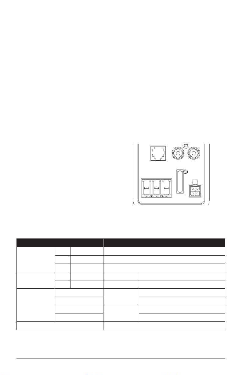
POWER CONNECTIONS PLUG
To connect the power wires and remote
turn-on wire to the amplifier, unplug the
“Power Connections” plug from the amplifier
panel (pull back firmly) and back out the set
screws on the connector plug using a Phillips
head screwdriver. Strip 3/8 inch (10 mm) of
insulation from the end of each wire and insert
the bare wire into the receptacle on the power
connector plug, seating it firmly so that no
bare wire is exposed. While holding each wire
in place, tighten each set screw firmly, taking
care not to strip the head of the screw.
Warning! Never make power connections with
a “live” wire. Always disconnect the negative
battery post before making any connections or
adjustments to a 12V power connection! Failure
to make safe, tight, high-integrity connections
can result in fire and extensive damage!
Remote
Level
Control
(L) (R)
Low-Level Inputs
Power Connections
+12 VDC GND Remote
FUSE
(30A)
High-Level
Inputs
Connection Description
Power
Connections
Low-Level Inputs
(RCA Jacks)
High-Level Inputs
(4-Pin
Connector)
Remote Level Control RJ11 Input Jack for RBC-1 (sold separately)
+ +12 VDC Positive (+12V) Power Connection
– GND Negative (GND) Ground Connection
R Remote Positive (+12V) Remote Turn-On Input
(L) White RCA Ch. 1 Input Left Channel Signal Input
(R) Red RCA Ch. 2 Input Right Channel Signal Input
White
White/Black (–) Left Channel Negative
Gray
Gray/Black (–) Right Channel Negative
Ch. 1 Input
Ch. 2 Input
(+) Left Channel Positive
(+) Right Channel Positive
MicroSub+ / PowerWedge+ with DCD™ Amplifier Technology 3
Page 4

Turn-On
50
80
125100
200
Low-Pass
Filter Freq. (Hz)
Turn-On
Mode
Remote
Input
Sensitivity
Min. Max.
Signal | DC | Rem 0 | 180 deg.
Output
Polarity
Mode
Low-Pass
Filter Freq. (Hz)
80
50
Output
125100
Polarity
0 | 180 deg.
200
CONTROL PANEL SETTINGS
AND ADJUSTMENTS
Use the amplifier’s panel mounted settings and
controls to integrate and adjust the performance
Input
Sensitivity
Min. Max.
Signal | DC | Rem
of your subwoofer system to your vehicle and
listening preference.
Switch Setting Mode / Function
Input
Sensitivity
Turn-On
Mode
Variable
Rem
DC
Signal
Adjusts the input stage of the amplier to match the source unit’s output
voltage for maximum clean output (refer to Appendix A)
Conventional
(Preferred)
DC-Oset Sensing
(Auto)
Signal
Sensing (Auto)
Connect to the source unit’s +12V remote turn-on output
Turns on and o by detecting the presence of small DC
signal in OEM audio outputs; connect to the source unit’s
high-level/speaker outputs
Turns on by detecting full-range audio signal in OEM
outputs; turns o after 30 seconds without signal;
connect to the source unit’s high-level/speaker outputs
Low-Pass
Filter Freq.
(Hz)
Output
Polarity
Variable
Adjusts the low-pass lter cuto frequency,
variable from 50-200 Hz, 12 dB/Octave
0 Normal speaker polarity
180 deg. Polarity reversed 180 degrees
Power
Protect
(green)
(red)
STATUS LED / PROTECTION CIRCUITRY
A bi-color LED located on the amplifier panel is
used to indicate the amplifier’s operational status.
“Power (green)”: Lights up green to indicate
the amplifier is turned on and operating normally.
“Protect (red)”: Lights up red to indicate the
amplifier’s protection circuitry has been activated
due to thermal overload. When the protection
mode is activated, the amplifier outputs are muted
to protect its circuitry. When the amplifier cools,
the amplifier will return to its normal operation
and the LED will turn green.
4 JL AUDIO
®
Page 5

Enclosure Specications
Model Driver(s)
ACP108LG-W3v3 (1) 8W3v3-0.40 0.40 Ω 250 W
ACP208LG-W3v3 (2) 8W3v3-0.40 0.20 Ω 500 W
ACP110LG-TW1 (1) 10TW1-0.25 0.25 Ω 400 W
ACP112LG-TW1 (1) 12TW1-0.25 0.25 Ω 400 W
ACS110LG-TW1 (1) 10T W1-0.25 0.25 Ω 400 W
ACS112LG-TW1 (1) 12T W1-0.25 0.25 Ω 400 W
Nominal
Impedance
RMS Power
@ 14.4V,
<1% THD+N
Dimensions
18.5 in x 11.125 in x 5.125 in
470 mm x 283 mm x 130 mm
36.625 in x 11.125 in x 5.125 in
905 mm x 283 mm x 130 mm
21 in x 13.5 in x 6.625 in
533 mm x 343 mm x 168 mm
23.75 in x 15.75 in x 9.25 in
603 mm x 400 mm x 235 mm
18.5 in x 11.125 in x 5 in
470 mm x 283 mm x 127 mm
21 in x 13.5 in x 6.625 in
533 mm x 343 mm x 168 mm
DCD™ Amplier Specications (All Models)
Input
Voltage Range
70 mV – 1.40 V (Low)
or
280 mV – 5.4 V (High)
Warning - Never use a DCD™ amplifier or its companion subwoofer(s) with incompatible, non-DCD™ products.
Filter Type, Range,
Slope
Low-Pass,
50 – 200 Hz,
12 dB/Octave
Doing so will void the warranty and may cause severe damage/injury.
Output
Polarity
0 or 180
degrees
Remote Bass
Controller
RBC-1 (sold
separately)
Power/GND Wire
8 AWG
(recommended)
Fuse
Rating
30A
MicroSub+ / PowerWedge+ with DCD™ Amplifier Technology 5
Page 6

APPENDIX A
Input Sensitivity Level Setting
Follow the steps below to adjust the input
sensitivity of the amplifier to achieve overall
system balance.
1) Turn off or set to center all processing (bass/
treble, loudness, EQ, etc.) on the source unit. Set
the source unit’s fader control to center position
and its subwoofer level control (if applicable) to ¾
of maximu m.
2) Turn the amplif ier’s “Input Sensitivity”
control to the “Min.” position.
3) While playing a dynamic audio track,
increase the head unit volume until the subwoofer
output distorts. Then, reduce the volume by one
step (or until the subwoofer’s output is no longer
distorted).
4) Increase the “Input Sensitivity” until the
subwoofer output is distorted.
5) Reduce the “Input Sensitivity” slightly until
the subwoofer output is no longer distorted.
6) Listen to the overall system and adjust the
“Input Sensitivity” downward if the subwoofer
output requires attenuation to achieve the desired
system balance.
APPENDIX B
With the optional RBC-1 Remote Level
Control (sold separately), you can control the
subwoofer volume from the front of the vehicle.
The RBC-1 connects to the jack labeled “Remote
Level Control” on the amplifier panel using
a standard telephone cable (supplied with the
RBC-1). When connected to the amplifier, the
Remote Level Control operates as follows. At
full counter-clockwise rotation, the audio will
mute completely. At full clockwise rotation, the
level will be the same as if the R BC-1 was not
connected at all. In other words, it operates strictly
as a level attenuator. Care should be ta ken to
securely mount this control in a manner that does
not interfere with the vehicle’s operation. When
setting the amplifier’s input sensitivit y, the Remote
Level Control should be unplugged or at full
clockwise rotation (maximum level).
PROTECT YOUR HEARING!
We value you as a long-term customer. For
that reason, we urge you to practice restraint in
the operation of this product so as not to damage
your hearing and that of others in your vehicle.
Studies have shown that continuous exposure to
high sound pressure levels can lead to permanent
(irreparable) hearing loss. This and all other
subwoofer systems are capable of producing
high sound pressure levels. Please limit your
continuous exposure to high volume levels. While
driving, operate your audio system in a manner
that still allows you to hear necessary noises to
operate your vehicle safely (horns, sirens, etc.).
6 JL AUDIO
®
Page 7

TROUBLESHOOTING
Problem Possible Cause Solution
How to properly set
input sensitivity
Amplifier doesn’t
turn on
Intermittent output,
fluctuates when I tap
on it or hit a bump
Output shuts off after
a while
Faulty fuse
Poor connection
integrity
Insufficient “Remote”
input
Poor connection
integrity
Overheating condition
(Thermal Protection)
Please refer to Appendix A to set the input sensitivity for
maximum, low-distortion output.
Remove fuse and check with continuity meter. Replace if
necessary.
Check “+12 VDC”, “GND”, and “Remote” leads for pinched
wires; ensure tight connections.
Make sure there is a sufficient +12V supply at the “Remote”
connection; if not, a relay may be required.
Make sure wiring insulation has been properly stripped back
at connection points for good contact area.
Make sure the signal input connections (low-level or highlevel) are making good contact.
Make sure enclosure is positioned allowing the amplifier
adequate space for ventilation and heat dissipation.
MicroSub+ / PowerWedge+ with DCD™ Amplifier Technology 7
Page 8

LIMITED WARRANT Y - AMPLIFIED SUBWOOFER SYSTEMS (USA)
JL Audio warrants this product to be free of defects in materials and workmanship for a period of two
(2) years from the original date of purchase. This warranty is not transferable and applies only to the
original purchaser from an authorized JL Audio dealer. Should service be necessary under this warranty
for any reason due to manufacturing defect or malfunction, JL Audio will (at its discretion), repair or
replace the defective product with new or remanufactured product at no charge. Damage caused by the
following is not covered under warranty: accident, misuse, abuse, product modification or neglect, failure
to follow installation instructions, unauthorized repair attempts, misrepresentations by the seller. This
warranty does not cover incidental or consequential damages and does not cover the cost of removing or
reinstalling the unit(s). Cosmetic damage due to accident or normal wear and tear is not covered under
wa rra nty.
Warranty is void if the product’s serial number has been removed or defaced.
Any applicable implied warranties are limited in duration to the period of the express warranty as
provided herein beginning with the date of the original purchase at retail, and no warranties, whether
express or implied, shall apply to this product thereafter. Some states do not allow limitations on implied
warranties, therefore these exclusions may not apply to you. This warranty gives you specific legal rights,
and you may also have other rights, which vary from state to state.
If you need service on your JL AUDIO product:
All warranty returns should be sent to JL Audio ’s Service Facility freight-prepaid through an
authorized JL Audio dealer and must be accompanied by proof of purchase (a copy of the original sales
receipt). Direct returns from consumers or non-authorized dealers will be refused unless specifically
authorized by JL Audio with a valid return authorization number. Warranty expiration on products
returned without proof of purchase will be determined from the manufacturing date code. Coverage may
be invalidated as this date is previous to purchase date. Non-defective items received will be returned
freight-collect. Customer is responsible for shipping charges and insurance in sending the product to JL
Audio. Freight damage on returns is not covered under warranty.
For Service Information in the U.S.A. please call
JL Audio Customer Service: (954) 443-1100
9:00 AM – 5:30 PM (Eastern Time Zone)
JL Audio, Inc
10369 North Commerce Pkwy.
Miramar, FL 33025
(do not send product for repair to this address)
International Warranties:
Products purchased outside the United States of America are covered only
by that country’s distributor and not by JL Audio, Inc.
SKU -011424-03-2015
 Loading...