

JL Audio Slampak SB-CAN-PODS1-M770, SlamPak SLPK-CAN-SPYDER1, 94491, 94490 Installation Manual
I N S T A L L A T I O N G U I D E
for th e
SLPK-CAN-SPYDER1
SKU#94491& 94490
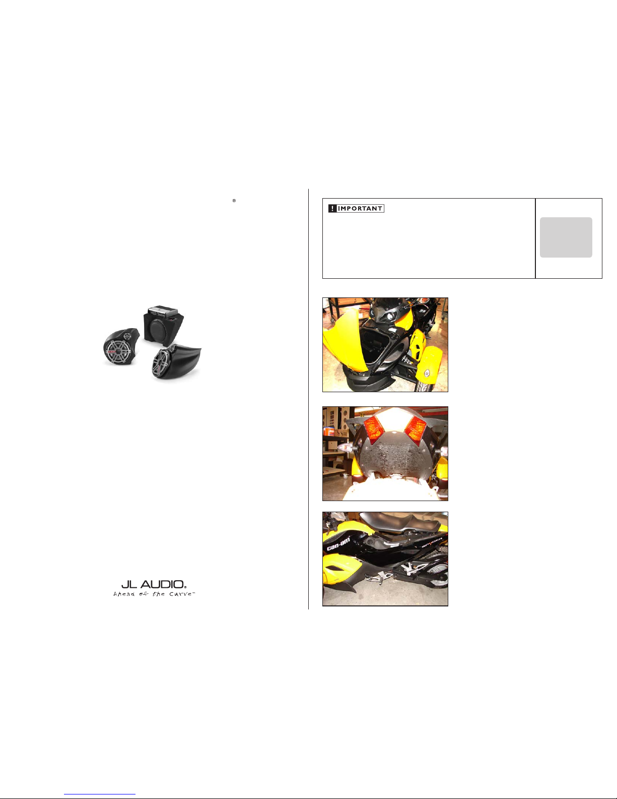
Thank you for choosing a JL Audio Slampak® for your motorcycle sound system. With proper
installation, your new vehicle-specific enclosed sound system will deliver years of listening pleasure.
We strongly recommend that you have your new Slampak® installed by your authorized JL Audio
dealer. The installation professionals employed by your dealer have the necessary tools and experience
to disassemble and reassemble your vehicle properly. Also, keep in mind that your warranty coverage
extends to 2 years if your system is installed or approved by your authorized JL Audio dealer. If you
prefer to perform your own installation, please read this installation guide completely
before beginning the process.
If you choose to perform the installation yourself, it is absolutely vital that
the Stealthbox
®
be properly mounted to the vehicle according to these
instructions. Failure to mount the enclosure properly presents two problems:
1) The sub-bass performance will suffer due to the movement of the enclosure
caused by the force exerted by the woofer(s).
2) A loose enclosure presents a serious safety hazard in the event of a collision
or sudden deceleration.
S T E P 1
Empty out the front storage space of the motorcycle so that
you have a clean area to work in.
If you are only installing the pods, skip to
STEP 16.
Continued on Next Page
S T E P 2
Remove the bottom panel above the rear tire as show here
S T E P 3
Lift the seat, remove the panel that simulates a gas tank at
the top center of the motorcycle. Remove the two panels
labelled “can-am” (one on each side of the motorcycle) and
the two panels labelled “spyder” (one on each side of the
motorcycle).
SLPK-CAN-SPYDER1_INSTR_SKU# 011312
INS TALLATIO N
D I F F I C U LT Y :
35
OU T
OF
EST IMATED TIME:
1 H OUR
SlamPak
Continued on Next Page
SLPK-CAN-SPYDER1_INSTR_SKU# 011312
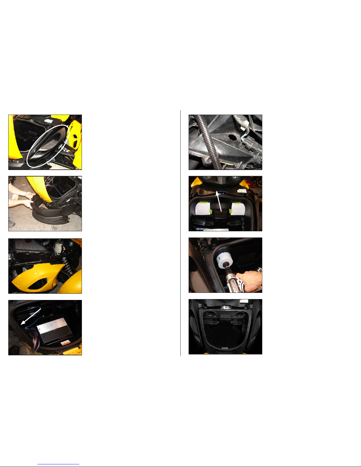
S T E P 7
Looking down from the top front of the storage
compartment, notice where the wire loom enters the
compartment.
S T E P 6
The harness for power, ground, remote turn on, signal and
speakers will come down the right side of the motorcycle
and enter the storage compar tment in the upper right rear
corner as shown below.
S T E P 5
Remove the front Air dam.
S T E P 4
Remove the air duct body panels as indicated by the image
at left. (One on each side of the motorcycle). There may be
auxiliary lights installed in this panel, unplug them as the
panel is removed.
If you are
ONLY installing the pods and NOT the full
system, but will be installing an amplifier in the front storage
compartment, only remove the air duct body panel on
the right hand side (where the harness enters the storage
compartment (as seen in
STEP 5 below), skip to STEP 6.
Page 2 • JL Audio, Inc 2009
S T E P 9
If you are
ONLY installing the pods and NOT the full system,
skip to STEP 16.
The two templates shown can be found on the last two
pages of the install manual, cut them out and position them
as shown.
Remove the panel directly above the storage compar tment
as indicated by the arrow.
S T E P 1 1
Mount the bevelled hole trims as shown using the 8
supplied #6-1 x 3/4” Phillips head screws (4 per trim).
S T E P 1 0
Mark the center positions of each template and cut the two
holes, the holes should be 3-5/8” in diameter after they are
cut.
USE ALL PRECAUTIONS WHEN CUTTING/DRILLING!
S T E P 8
Looking up from the front right tire, use a 1-1/8” hole- saw
to cut a hole for the harness to come through as seen in
STEP 7.
Before drilling, always make sure that you are not
going to be drilling into any gas lines, brake lines,
tires, transmission lines, electrical wiring, exhaust
systems or anything else that might cause a
reduction in your weekly pay.
Always wear eye protec tion when drilling!
Continued on Next Page
SLPK-CAN-SPYDER1_INSTR_SKU# 011312
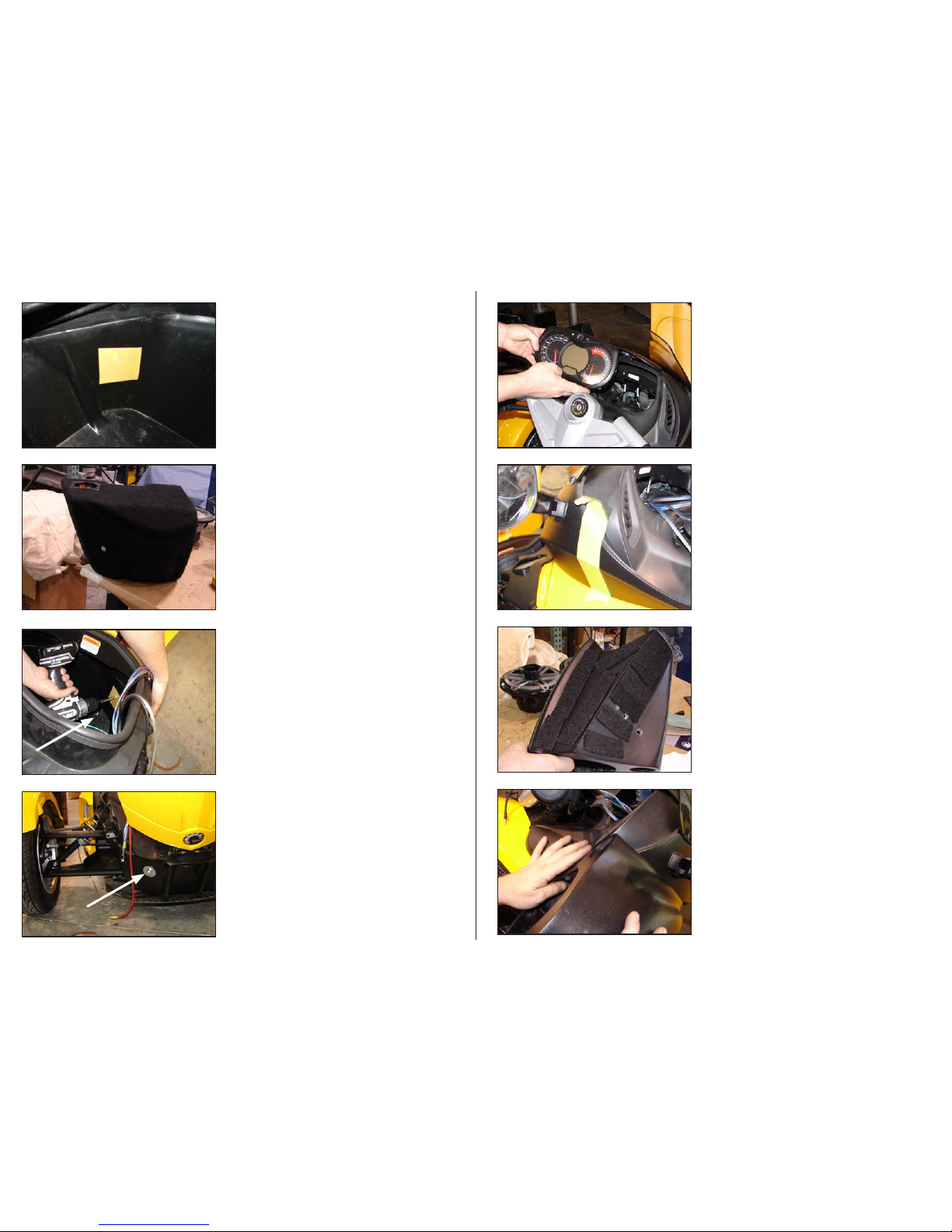
S T E P 1 5
Install the 3/8-16 x 1-1/4” Hex Head Bolt through the included
Split Lock Washer, the 1-1/4” Fender Washer and the hole
drilled in STEP 14 into the enclosure, tighten this fastener
down.
Once this fastener is tight, the front air dam can be reinstalled.
S T E P 1 4
Drill a 5/16” hole where the indentation was made in STEP 13.
Before drilling, always make sure that you are not
going to be drilling into any gas lines, brake lines,
tires, transmission lines, electrical wiring, exhaust
systems or anything else that might cause a
reduction in your weekly pay.
Always wear eye protec tion when drilling!
S T E P 1 3
Thread the 3/8-16 x 1-1/4” Hex Head Bolt all the way into
the enclosure. Press the enclosure down into the storage
compartment towards the right front corner, the Hex Head
Bolt will leave an indentation in the wax square.
Once you’ve confirmed the indentation in the wax square,
remove the Hex Head Bolt from the enclosure.
S T E P 1 2
Looking down and towards the front right corner of the
storage compartment, position the wax square as shown.
Page 3 • JL Audio, Inc 2009
S T E P 1 7
Put a length of masking tape as shown on each side of the
top fairing.
S T E P 1 9
Align pod with the back edge matching the fairing (as
shown) and the front corners as show in
STEP 20.
S T E P 1 8
Remove the larger speaker from each pod, the smaller
speaker can remain in the pod. The speakers are only
secured in the pods for shipping with 3- screws, use all six
when re-installing. (In the following pictures, both speakers
have been removed, this is NOT necessary!)
Position foam strips as shown on each pod.
Note the location of the three holes in the pods, two will be
used to mount the pod, the third will be the wire run.
S T E P 1 6
Remove gauge cluster as shown by lifting top panel then
depressing two locking tabs on top of the cluster.
 Loading...