

Page 1

NMF691 Series User Manual
G03-NMF691-F
Rev: 4.0
Release date: Octob er 1, 2019
Trademark:
* Specifications and Information contained in this docume ntation ar e fur nish ed for i nfo r mation u se only, and are
subject to change at any time without notice, and should not be construed as a commitment by manufacturer.
Page 2

TABLE OF CONTENT
ENVIRONMENTAL SAFETY INSTRUCTION ........................................................................... iii
ENVIRONMENTAL PROTECTION ANNOUCEMENT .............................................................. iii
USER’S NOTICE ....................................................................................................................... iv
MANUAL REVISION INFORMATION ....................................................................................... iv
ITEM CHECKLIST ..................................................................................................................... iv
CHAPTER 1 INTRODUCTION OF THE MOTHERBOARD
1-1 SPECIFICATION ......................................................................................................... 1
1-2 LAYOUT DIAGRAM .................................................................................................... 2
CHAPTER 2 HARDWARE INSTALLATION
2-1 JUMPER SETTING ..................................................................................................... 6
2-2 CONNECTORS AND HEADERS ................................................................................ 10
2-2-1 REAR I/O BACK PANEL CONNECTORS.................................................... 10
2-2-2 MOTHERBOARD INTERN AL CONNECTO RS ............................................ 11
2-2-3 HEADER PIN DEFINITION ........................................................................... 14
CHAPTER 3 INTRODUCING BIOS
3-1 ENTERNING SETUP ................................................................................................... 19
3-2 BIOS MENU SCREEN ................................................................................................ 19
3-3 FUNCTION KEYS ....................................................................................................... 20
3-4 GETTING HELP .......................................................................................................... 20
3-5 MENU BARS ............................................................................................................... 21
3-6 MAIN MENU ................................................................................................................ 21
3-7 ADVANCED MENU ..................................................................................................... 22
3-8 CHIPSET MENU .......................................................................................................... 30
3-9 SECURITY MENU ....................................................................................................... 32
3-10 BOOT MENU ............................................................................................................... 33
3-11 SAVE & EXIT MENU ................................................................................................... 34
ii
Page 3

Environmental S afety Instruction
Avoid the dusty, humidity and temperature extremes. Do not place the product in
any area where it m ay become wet.
0 to 40 centigrade is th e suitabl e tem perat ure. (The fig ure c omes from the r eques t
of the main chipset)
Generally speaking, dramatic changes in temperature may lead to contact
malfunction and crackles due to constant thermal expansion and contraction from
the welding spots’ that connect components and PCB. Computer should go
through an adaptive phase before it boots when it is moved from a cold
environment to a warmer one to avoid condensation phenom enon. These water
drops attached on PCB or the surface of the components can bring about
phenomena as minor a s computer instabi lity resulted fr om corrosio n and oxi dation
from components and PCB or as major as short circuit that can burn the
components. Suggest starting the computer until the temperature goes up.
The increasing temperature of the capacitor may decrease the life of computer.
Using the close case may decrease the life of other device because the higher
temperature in the inner of the case.
Attention to the heat sink when you over-clocking. The higher temperature may
decrease the life of the device and burned the capacitor.
Environmental Prote ction Announc ement
Do not dispose this electronic device into the trash while discarding. To minimize
pollution and ensure environment protection of mother earth, please recycle.
iii
Page 4

USER’S NOTICE
COPYRIGHT OF THIS MANUAL BELONGS TO THE MANUFACTURER. NO PART OF THIS MANUAL,
INCLUDING THE PRODUCTS AND SOFTWARE DES CRIBED IN I T MAY BE REPRO DUCED, TR ANSMITTED
OR TRANSLATED INTO ANY LANGUAGE IN ANY FORM OR BY ANY MEANS WITHOUT WRITTEN
PERMISSION OF THE MANUFACTURER.
THIS MANUAL CONTAINS ALL INFORMATION RE QUIRED TO USE THIS MOTHER-BOARD SERIES AND WE
DO ASSURE THIS MANUAL MEETS USER’S REQUIREMENT BUT WILL CHANGE, CORRECT ANY TIME
WITHOUT NOTICE. MANUFACTURER PROVIDES THIS M ANU AL “AS IS” WITHOUT WARRANTY OF ANY
KIND, AND WILL NOT BE LIABLE FOR ANY INDIRECT, SPECIAL, INCIDENTAL OR CONSEQUENTIAL
DAMAGES (INCLUDING DAMAGES FOR LOSS OF PROFIT, LOSS OF BUSINESS, LOSS OF USE OF DATA,
INTERRUPTION OF BUSINESS AND THE LIKE).
PRODUCTS AND CORPORATE NAMES APPEARING IN THIS MANUAL MAY OR MAY NOT BE
REGISTERED TRADEMARKS OR COPYRIGHTS OF THEIR RESPECTIVE COMPANIES, AND THEY ARE
USED ONLY FOR IDENTIFICATION OR EXPLANATION AND TO THE OWNER’S BENEFIT, WITHOUT
INTENT TO INFRINGE.
Manual Revision Information
Reversion Revision History Date
4.0 Fourth Edition Octob er 1, 2019
Item Checklist
Motherboard
Cable(s)
I/O Back panel shield
iv
Page 5

Spec
Description
Design
m-ATX form factor; PCB size: 24.4 x24.4 cm
Chipset
Intel® H110 Express Chipset
* for detailed CPU sup port i nform ati on ple ase visit our website
2*DDR4 RAM module slot
Support dual-channel f unc ti o n
1 * PCI-Express x16 slot (PCIE1)
1 * Full-size Mini-PCIE (MPE)
3 * SATAIII 6Gb/s port (SATA1/2/3)
2242/2260/2280/22110 SATA SSD)
Integrated with 2* Realtek RTL8111G Gigabit PCI-E LAN
10/100/1000Mbps Ethernet data transfer rate
Realtek ALC662 6-channel Audio Codec integrated
Audio driver and utility included
BIOS
AMI 64MBit Flash ROM
8* COM port header (COM3/4/5/6/7/8/9/10)
Chapter 1
Introduction of the Motherboard
1-1 Specification
Supports Intel® Core™ i7, Core™ i5, Core™ i3 series,
CPU Socket
Memory Slots
Pentium® processor in LAG1151 Package (Max. 65W)
Supporting 2* 2133MHz DDR4 RAM Module, expandable
to 32 GB (Maximum)
Expansion Slots
Storage
LAN Chip
Audio Chip
Multi I/O
1 * PCI-Express x1 slot (PCIE2)
2 * PCI slot (PCI1/2)
1* M.2 Socket 3 connector (Socket 3, M-key, support type
chip
Support Fast Ethernet LAN func ti on of prov i di ng
Rear Panel I/O:
2* Serial port connector(COM1_2, COM1 supports
RS232/422/485 function )
2* USB 2.0 port connector
1* HDMI port connector
1* DVI-D port connector
1* VGA port connector
2* RJ-45 LAN port connector
4* USB 3.0 port connector
1*3-jack audio connector (Line-in, Line-out, MIC)
Internal I/O Connectors & Headers:
1 *24-pin main power connector
1 *8-pin 12V power connector
1* Front panel audio header
1* SPDIF-out header
2* LAN Status indicator header(LAN1_LED/LAN2_LED)
1
Page 6
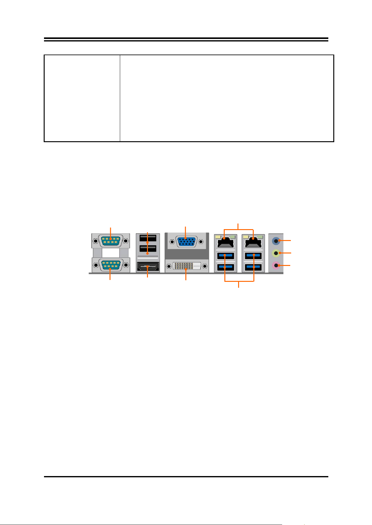
1* GPIO header
USB
USB
3* FAN header
Serial Port
(COM2)
USB 2.0 Ports
HDMI Port
VGA Port
DVI-D Port
RJ-45 LAN Ports
USB 3.0 Ports
Line-IN
Line-OUT
MIC-IN
Serial Port
(COM1)
1* Front panel header
1* Speaker header+ 1* POWER LED header
1* 4-pin front panel USB 2.0 header for 1* expansion
2.0 port
1* 9-pin front panel USB 2.0 header for 2* expansion
2.0 port
1* PS/2 KB & MS header
1* SMBUS header
1-2 Layout Diagram
Rear IO Diagram
* Note: Many PCs now include XHCI USB controllers which allow for the support of
USB 3.0 and higher USB speeds. This inclusion of XHCI controllers has lessened the
need for EHCI USB controllers within platforms. However, legacy operating systems
(OS) may not natively recognize XHCI controllers. You might need to pre-install XHCI
driver while desiring to install a non-XHCI OS (ex.Windows* 7) on Intel platforms
which do not include EHCI controllers. Please contact your representative for more
details.
2
Page 7
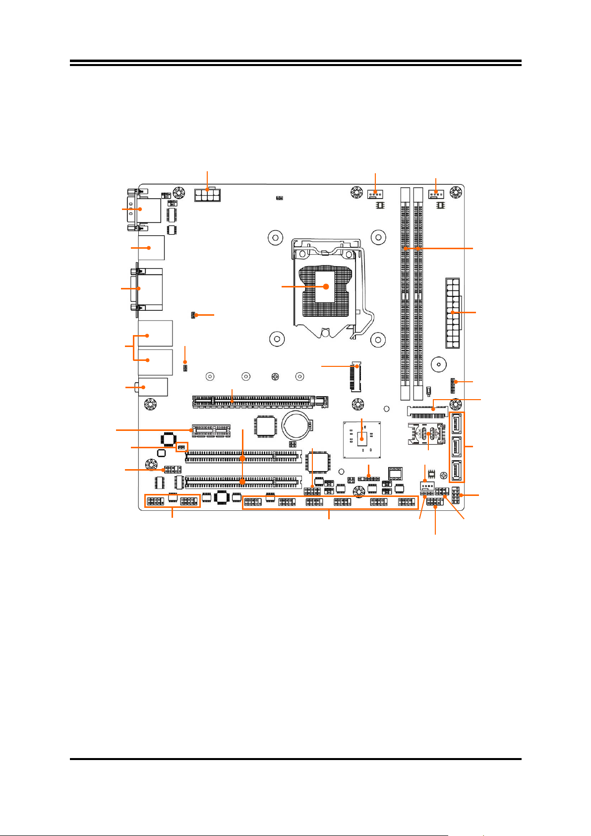
ATX 12V
Power Connector
Serial Ports
USB 2.0 Ports
VGA Port
RJ-45 LAN Ports
Over USB 3.0 Ports
Audio
CPU Socket
Intel H110 Chipset
SATAIII Ports
ATX Power
Connector
SMBUS Header
PS2KBMS Header
SYSFAN2 Header
GPIO Header
Serial Port Headers
Serial Port Headers
USB 2.0 Headers
PWR LED
& Speaker Header
USB 2.0 Headers
Front Panel
Header
CPUFAN Header
SYSFAN1 Header
DDR4
Front Panel
Audio Header
HDMI_SPDIF
PCI Slots
(PCI12)
M.2 Socket 3 C o n ne ctor
(MH1/2/3/4) *
Full-size
*SIM Card Slot
LAN2_LED Header
LAN1_LED Header
Motherboard Internal Diagram
over HDMI Port
over DVI-D Port
Connectors
PCI Express 2.0 x 1 Slot
(PCIE2)
Header
(COM10/9)
LGA 1151
PCI Express 2.0 x 16 Slot (PCIE1)
(COM8/7/6/5/4/3)
DIMM Slot x 2
Mini-PCIE Slot
(MPE) *
(SATA1/2/3)
*Note: SIM card slot only work when c ompatible SIM card ins talled & 3G LAN card instal led in MPE
Mini-PCIE slot.
3
Page 8
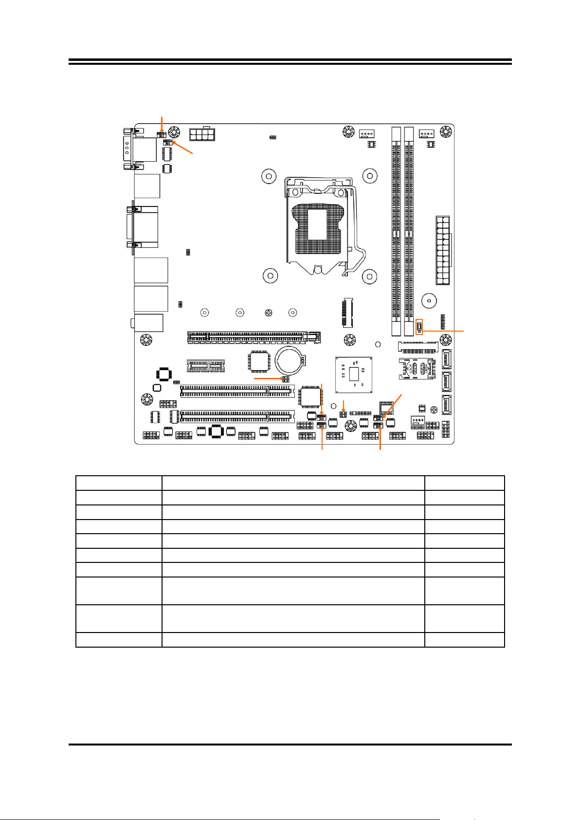
Jumper
Name
Description
JPCOM1
COM1 Port Pin9 Function Select
4-pin Block
JPCOM2
COM2 Port Pin9 Function Select
4-pin Block
JPCOM3
COM3 Header Pin9 Functi on Sel ect
4-pin Block
JPCOM4
COM4 Header Pin9 Function Sel ec t
4-pin Block
JPCOM5
COM5 Header Pin9 Function Select
4-pin Block
JPCOM6
COM6 Header Pin9 Function Sel ec t
4-pin Block
AT_COPEN
Pin (1-2): ATX Mode / AT Mode Select
Pin (3-4): Case Open Message Display Function
4-pin Block
JBAT
Pin (1-2): Clear CMOS RAM Function Setting
Pin (3-4): DFDS Override
4-pin Block
JP1
Mini PCI-E Slot (MPE)VCC3.3V/3.3VSB Select
3-pin Block
AT_COPEN
JBAT
JPCOM5
JPCOM6
JPCOM3
JPCOM4
JPCOM2
JPCOM1
JP1
Motherboard Jumper Position
Jumper
4
Page 9

Connector
Name
ATXPWR
ATX Main Power Connector
ATX12V
ATX 12V Power Connector
COM1_2
Serial Port COM Connector X2
USB1
USB 2.0 Port Connector X2
HDMI
HDMI Port Connector
CRT_DVI
Top: VGA Port Connector
Bottom: DVI-D Port Connector
UL1/UL2
Top:RJ-45 LAN Connector X2
Middle & Bottom: USB 3.0 Port Connector X4
AUDIO
Top: Line-in Connector
Bottom: MIC Connector
SATA1/2/3
SATAIII Connector X3
Header
Name
Description
FP_AUDIO
Front Panel Audio Header
9-pin Block
SPDIF
HDMI_SPDIF Out Header
2-pin Block
LAN1_LED/ LAN2_LED
LANLED Activit y Header
2-pin Block
COM 3/4/5/6/7/8/9/10
Serial Port Header
9-pin Block
GPIO_CON
GPIO Header
10-pin Block
JW_FP
PWR LED/ HD LED/ Power Button
9-pin Block
SPK_LED
Power LED & Speaker Header
7-pin Block
FP_USB2
USB 2.0 Header
4-pin Block
FP_USB1
USB 2.0 Header
9-pin Block
PS2KBMS
PS/2 Keyboard & Mouse Header
6-pin Block
SMBUS
SMBUS Header
5-pin Block
SYSFAN1/SYSFAN2/CPUFAN
FAN Header
4-pin Block
Connectors
Middle: Line-out Connector
Headers
/Reset
5
Page 10
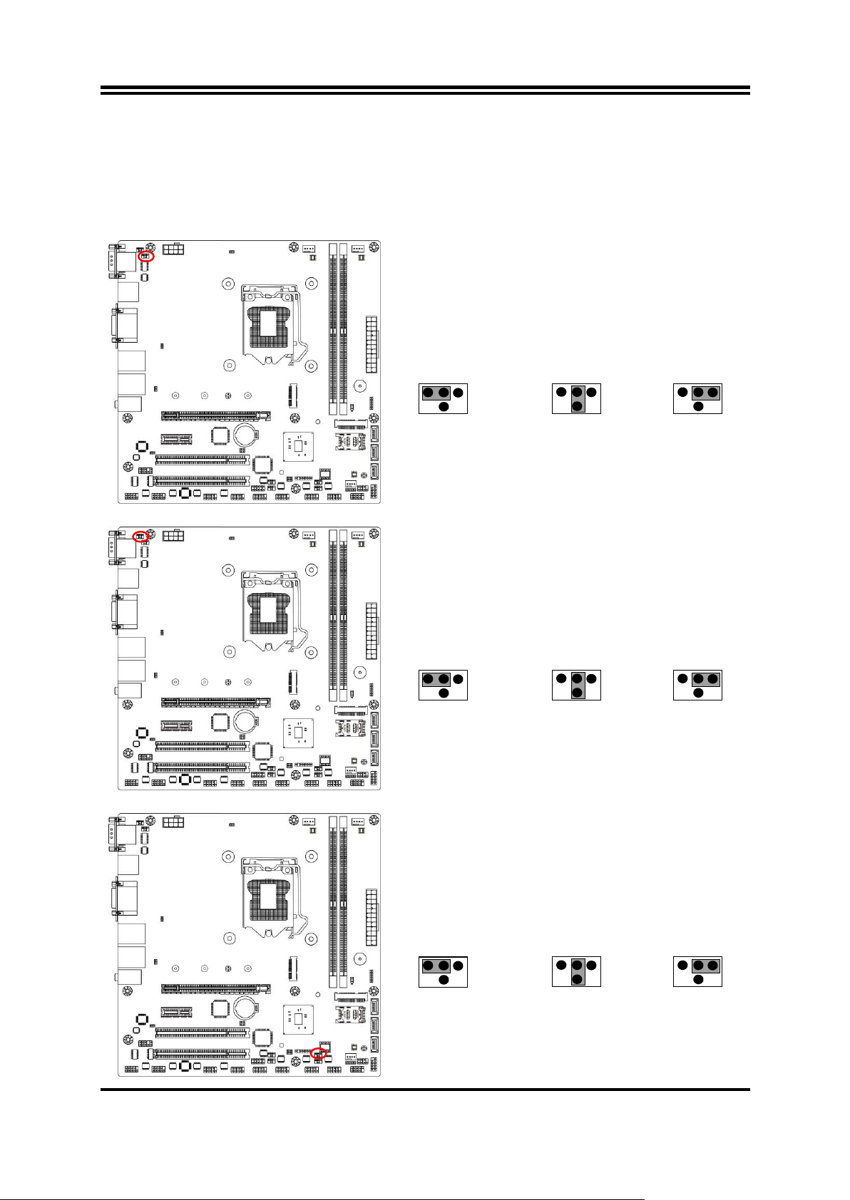
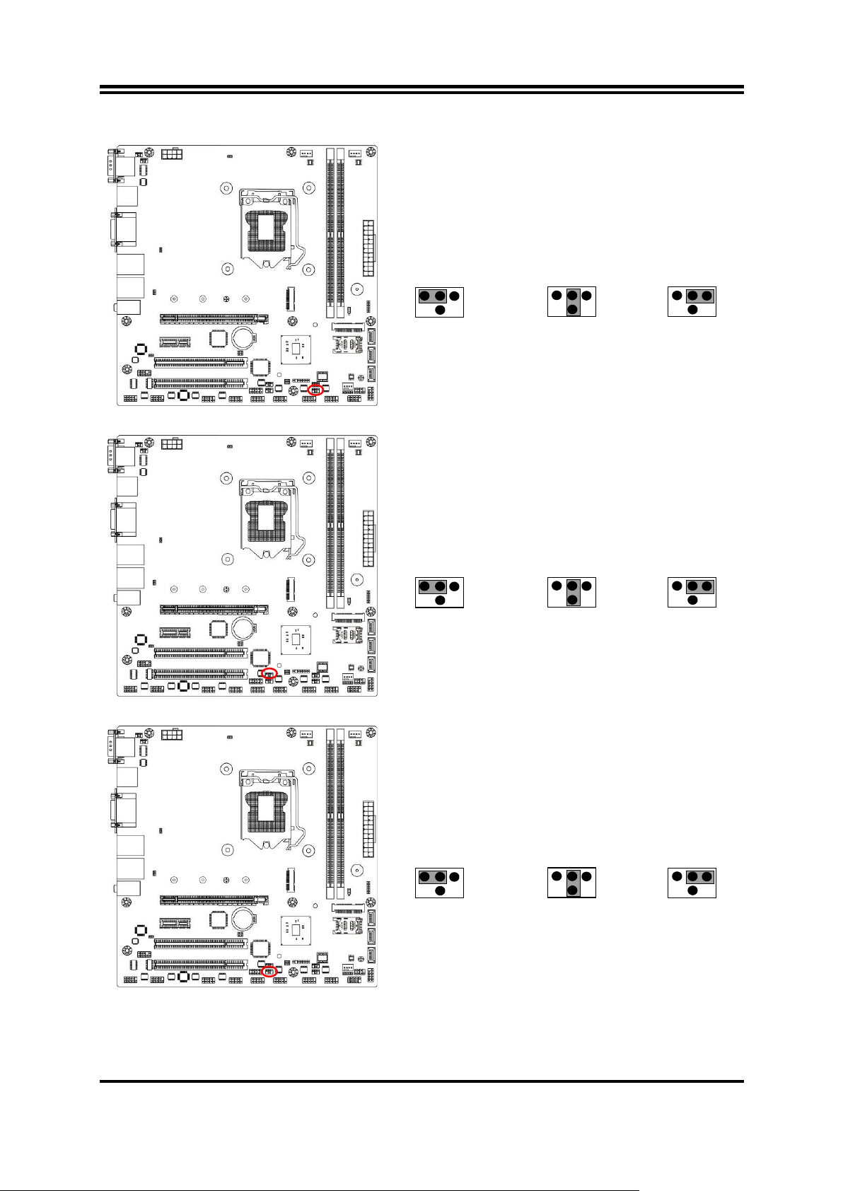
JPCOM1→COM1 Port
4-6 Closed:
RI= 12V;
6 4 2
3-4 Closed:
RI= 5V;
2-4 Closed:
RI=RS232
3
1
5
1
3
5
2
4
6
1
3
5
2
4
6
JPCOM2→
COM2 Port
4-6 Closed:
RI= 12V;
6 4 2
3-4 Closed:
RI= 5V;
2-4 Closed:
RI=RS232
3
1
5
1
3
5
2
4
6
1
3
5
2
4
6
JPCOM3→COM3 Header
4-6 Closed:
RI= 12V;
6 4 2
3-4 Closed:
RI= 5V;
2-4 Closed:
RI=RS232
3
1
5
1
3
5
2
4
6
1
3
5
2
4
6
Chapter 2
Hardware Installation
2-1 Jumper Setting
JPCOM1 (4-pin): COM1 Port Pin9 Function Se lect
JPCOM2 (4-pin): COM2 Port Pin9 Function Select
JPCOM3 (4-pin): COM3 Header Pin9 Function Select
6
Page 11
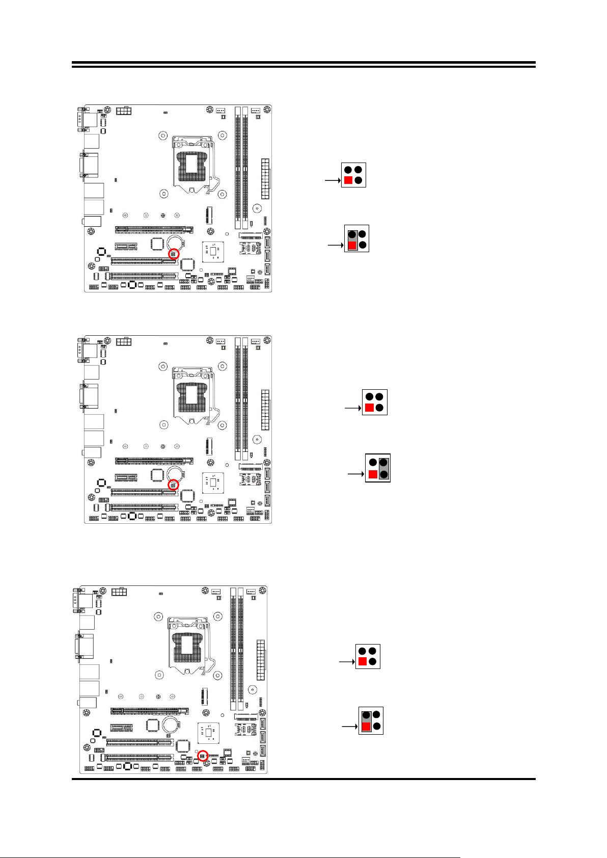
JPCOM4→COM4 Header
4-6 Closed:
RI= 12V;
6 4 2
3-4 C
losed:
RI= 5V;
2-4 Closed:
RI=RS232
3
1
5
1
3
5
2
4
6
1
3
5
2
4
6
JPCOM5→COM5 Header
4-6 C
losed:
RI= 12V
;
6 4 2
3-4 Closed:
RI= 5V;
2-4 Closed:
RI=RS232
3
1
5
1
3
5
2
4
6
1
3
5
2
4
6
JPCOM6→COM6 Header
4-6 Closed:
RI= 12V;
6 4 2
3-4 Closed:
RI= 5V;
2-4 Closed:
RI=RS232
3
1
5
1
3
5
2
4
6
1
3
5
2
4
6
JPCOM4 (4-pin): COM4 Header Pin9 Function Select
JPCOM5 (4-pin): COM5 Header Pin9 Function Select
JPCOM6 (4-pin): COM6 Header Pin9 Function Select
7
Page 12
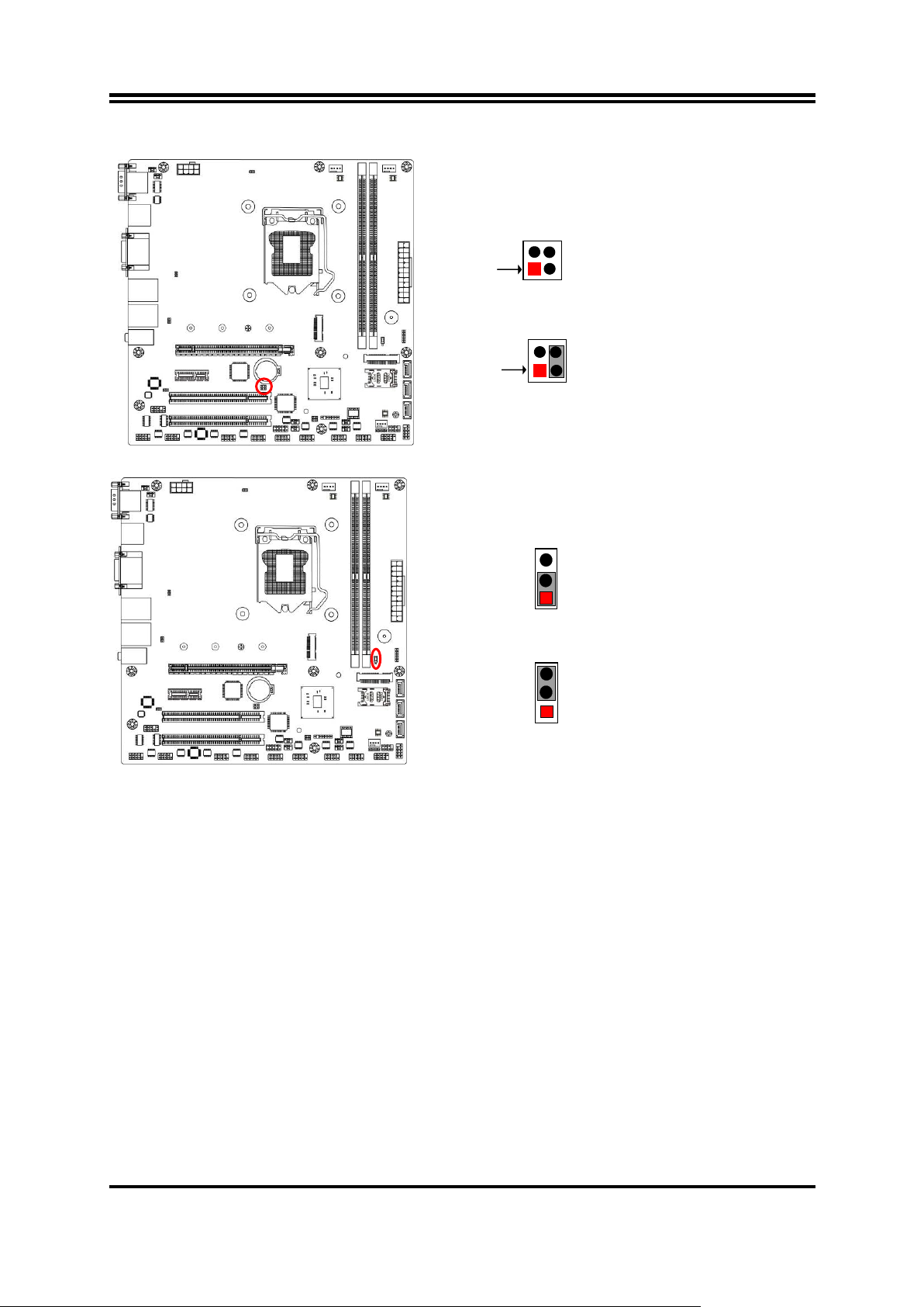
Pin(1-2) of AT_COPEN→ATX/AT
Mode
Select
Pin 1
4
2
Pin 1
2
4
3
3
1-2 Open:
ATX Mode Selected(Default);
1-2Closed: AT Mode Selected.
Pin(3-4) of AT_COPEN→Case Open
Pin 1
3 2
Pin 1
2
4
4
3
3-4 Open: Normal
(Default);
3-4 Closed: Case Open Funcion Selected.
Pin(1-2) of JBAT→Clear CMOS
Pin 1
4
2
Pin 1
2 4 3
3
1-2 Open: Normal(Default);
1-2 Closed: Clear CMOS RAM Settings.
Pin(1-2)of AT_COPEN (4-pin): ATX Mode/AT Mode Select
*ATX Mode Selected: Press power button to power on after power input ready;
AT Mode Selected: Directly power on as power input ready.
Pin(3-4)of AT_COPEN (4-pin): Case Open Message Display Select
Use needs to enter BIOS and enable ‘Case Open Detect’ function. In this case if you
case is removed, next time when you restart your computer a message will be
displayed onscreen to inform you of this.
Pin(1-2)of JBAT (4-pin): Clear CMOS RAM Function Settings
8
Page 13
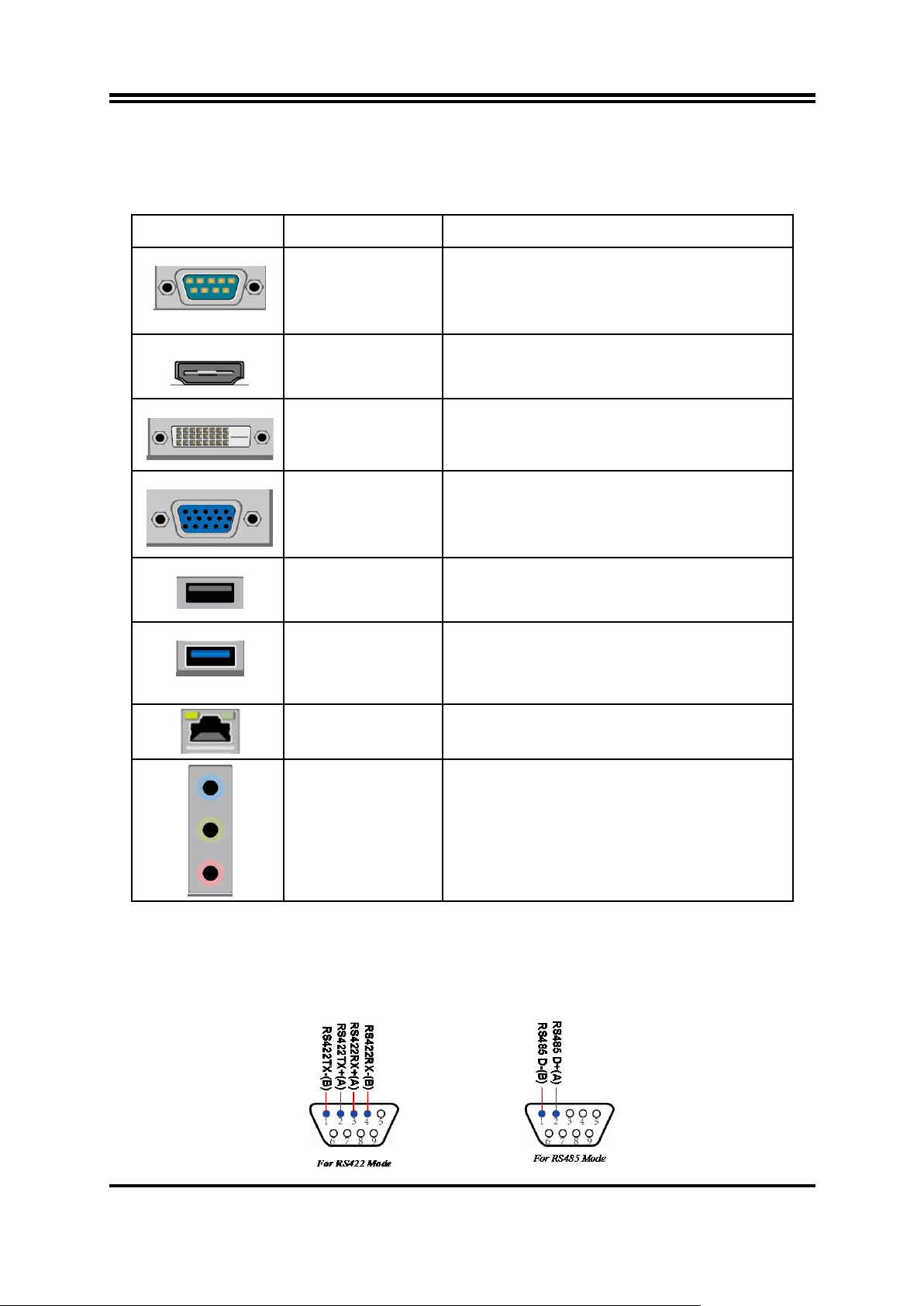
Pin(3-4) of JBAT→DFDS Override
Pin 1
3
2
Pin 1
2
4
4
3
3-4 Open: Normal (Default);
3-4 Closed: DFDS Override.
2-3 Closed: MINI PCI
-E Slot VCC = 3.3VSB.
JP1→ Mini-PCIE
Slot VCC Select
1-2 Closed: MINI PCI-E Slot VCC= 3.3V;
3
1
1
3
Pin(3-4)of JBAT (4-pin): DFDS Override
JP1 (3-pin): Mini PCI-E (MPE) Slot VCC 3.3V/3.3 VSB Select
9
Page 14
(Max. resolution Support: 3840*2160@24Hz)
rate.
2-2 Connectors and Headers 2-2-1 Rear I/O Back Panel Connectors
*Refer to Page-2.
Icon Name Function
Mainly for user to connect external MODEM or
Serial Port
HDMI Port
DVI-D Port
VGA Port
other devices that supports
Serial Communications Interface.
*Note: COM1 supports RS232/422/485 function.
To connect display device that support HDMI
specification.
To connect display device that support DVI
specification.
(Max. resolution Support:1920*1200@60Hz)
VGA connector is the 15-pin D-subminiature
female connector; it is for the display devices,
such as the CRT monitor, LCD monitor and so on.
(Max. resolution Support:1920*1200@60Hz)
To connect USB keyboard, mouse or other
USB 2.0 Port
devices compatible with USB 2.0 specification.
To connect USB keyboard, mouse or other
USB 3.0 Port
RJ-45 LAN Port
Audio Connectors
devices compatible with USB 3.0 specification.
USB 3.0 ports supports up to 5Gbps data transfer
This connector is standard RJ-45 LAN jack for
Network connection.
BLUE:
GREEN: Line-out Connector
PINK : MIC Connector
Line-in Connector
COM1 (9-pin Block): RS232/422/485 Port
COM1 port can function as RS232/422/485 port. In normal settings COM1 functions
as RS232 port. With compatible COM cable COM1 can function as RS422 or RS 485
port. User also needs to go to BIOS to set ‘Transmission Mode Select’ for COM1
at first, before using specialized cable to connect different pins of this port.
10
Page 15
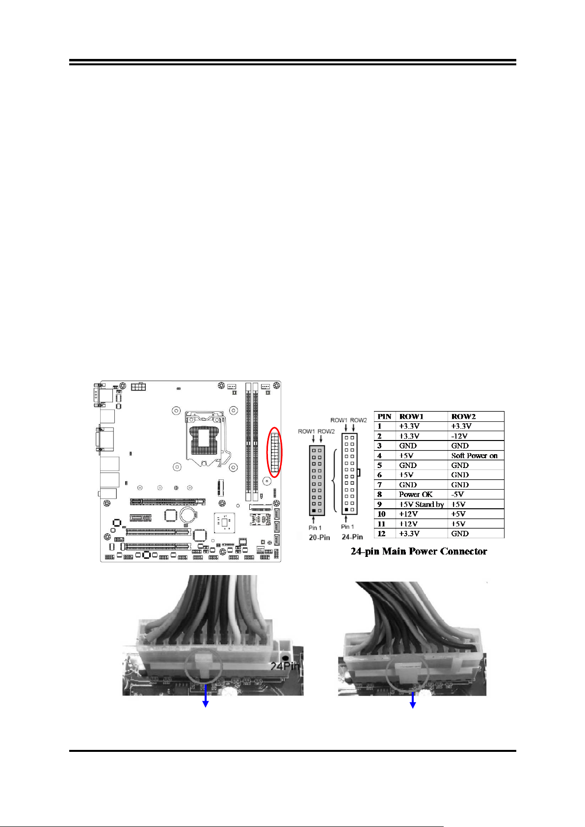
2-2-2 Motherboard Int ernal Connect ors
(1) ATXPWR (24-pin block): Main Power Connector
ATX Power Supply connector: This is a new defined 24-pins connector that usually
comes with ATX case. The ATX Power Supply all ow s us ing soft power on momentary
switch that con nec t fro m the front panel switch to 2-pi ns Power On jumper pole on the
motherboard. W hen the power switch on the back of the AT X power supply turned
on, the full power will not come into the system board until the f ront panel switch is
momentarily pressed. Press this switch again will turn off the power to the system
board.
** We recommend that you use an ATX 12V Specification 2.0-compliant power supply
unit (PSU) with a minimum of 350W power rating. This type has 24-pin and 4-pin
power plugs.
** If you intend to use a PSU with 20-pin and 4-pin power plugs, make sure that the
20-pin power plug can provide at least 15A on +12V and the power supply unit has a
minimum power rating of 350W . The system may become unstable or may not boot
up if the power is inadequate.
** If you are using a 20-pin power plug, please refer to Figure1 for power supply
connection. Power plug form power supply and power connectors from motherboard
both adopt key des ign t o avoi d mist ake ins tall ati on. Y ou can i nser t t he pow er pl ug i nto
the connector with ease only in the right direction. If the direction is wrong it is hard to
fit in and if you make the connection by force if is possible.
Figure1:20-pin power plug Figure 2:24-pin power plug
11
Page 16
Pin No.
Definition
1
GND
2
TXP
3
TXN
4
GND
5
RXN
6
RXP
7
GND
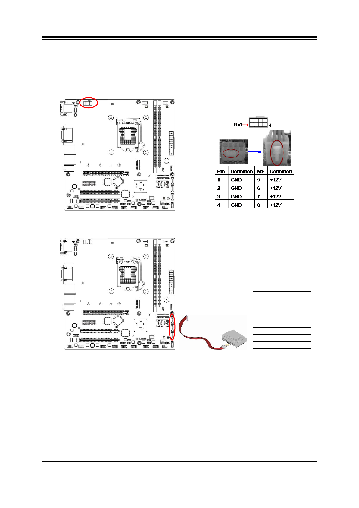
(2) ATX12V (8-pin block): 12V Power Connector
This is a new defined 8-pin connector that usually comes with ATX Power Supply that
supports extra 12V voltage to maintain system power consumption. Without this
connector might cause system unstable because the power supply can not provide
sufficient current for system.
(3) SATA1/2/3: SATAIII Port Connector
These connectors are high-speed SATAIII ports that support 6 GB/s transfer rate.
12
Page 17
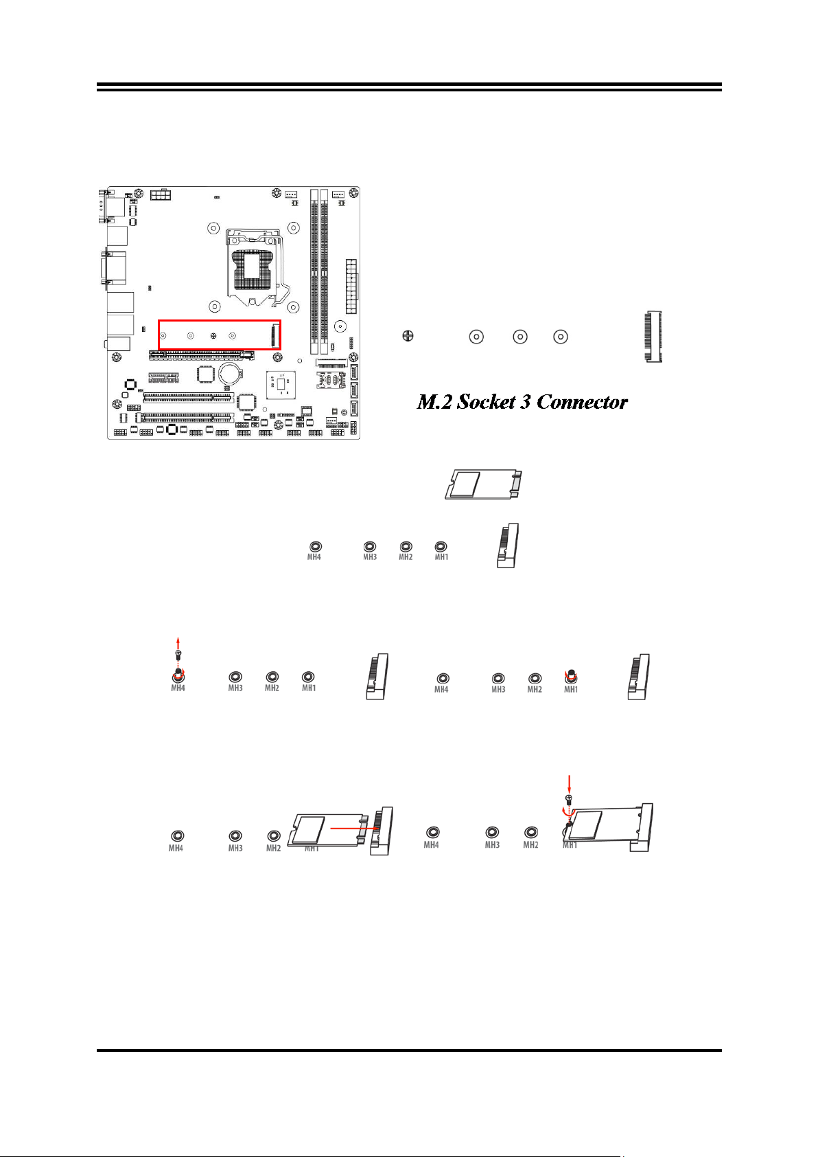
1. Prepare compatible M.2 SATA or M.2 SSD card. Deferent type of cards has different
length. Find corresponding nut location for further installation.
2. Remove the screw post and nut fixed at
by default (Skip step 2 & 3
to use the default nut).
3. Lock the screw post into the location
4. Align and insert corresponding M.2
5. Tighten up the screw to secure the
possible damage to the module.
(4) M2: M2 Socket 3 Connector
This M2 Socket 3 connector support compatible type 2242/2260/2280/22110 SATA SSD module.
M.2 Module Installation Guide
location MH4
and go straight to Step 4 if you are going
module, as the photo shows.
corresponding to the length of the
module.
module into the M.2 connector. Mare
sure not overtighten the screw to avoid
13
Page 18
Pin 1
MIC2-L
LINE OUT-L
MIC2-R
LINE OUT-R
SENSE
GND
LINE_OUT_JD
MIC_JD
DETECT
2
Pin1
SPDIF_OUT
GND
Pin1
LED+
LED-
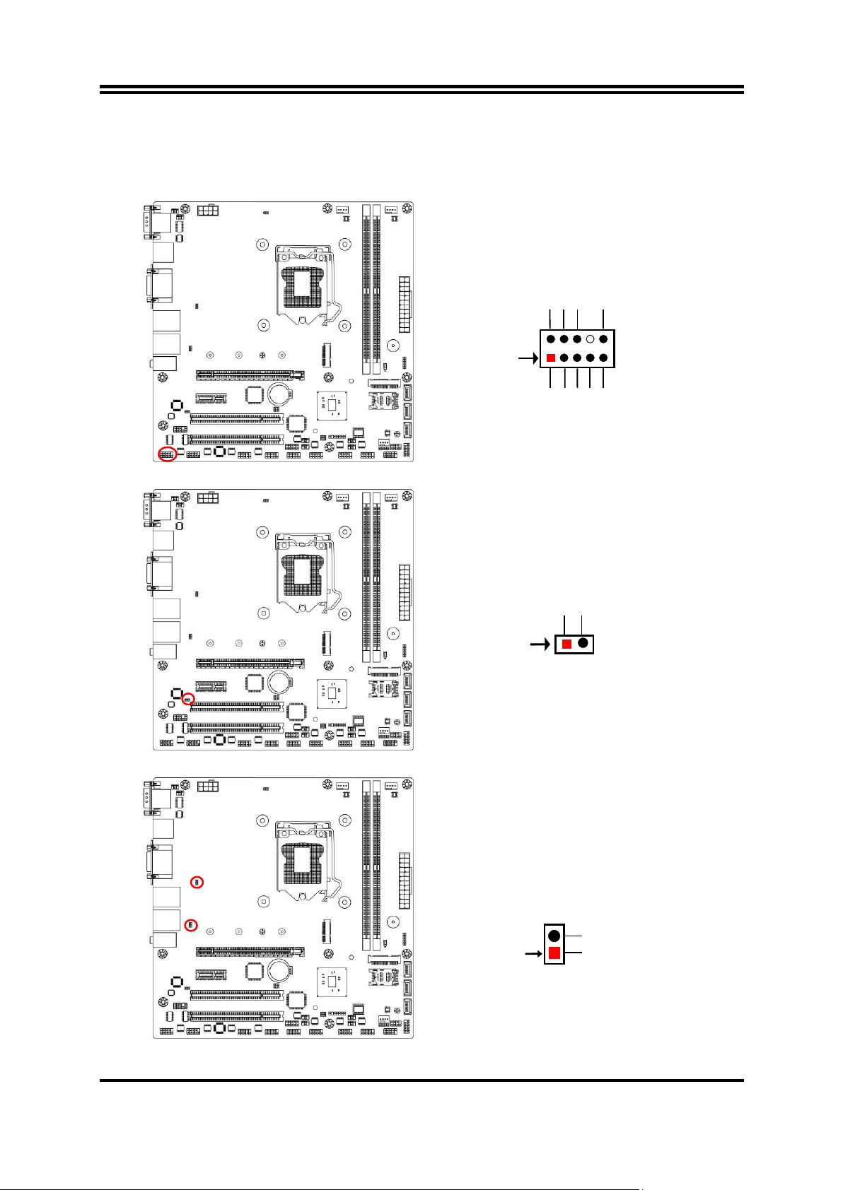
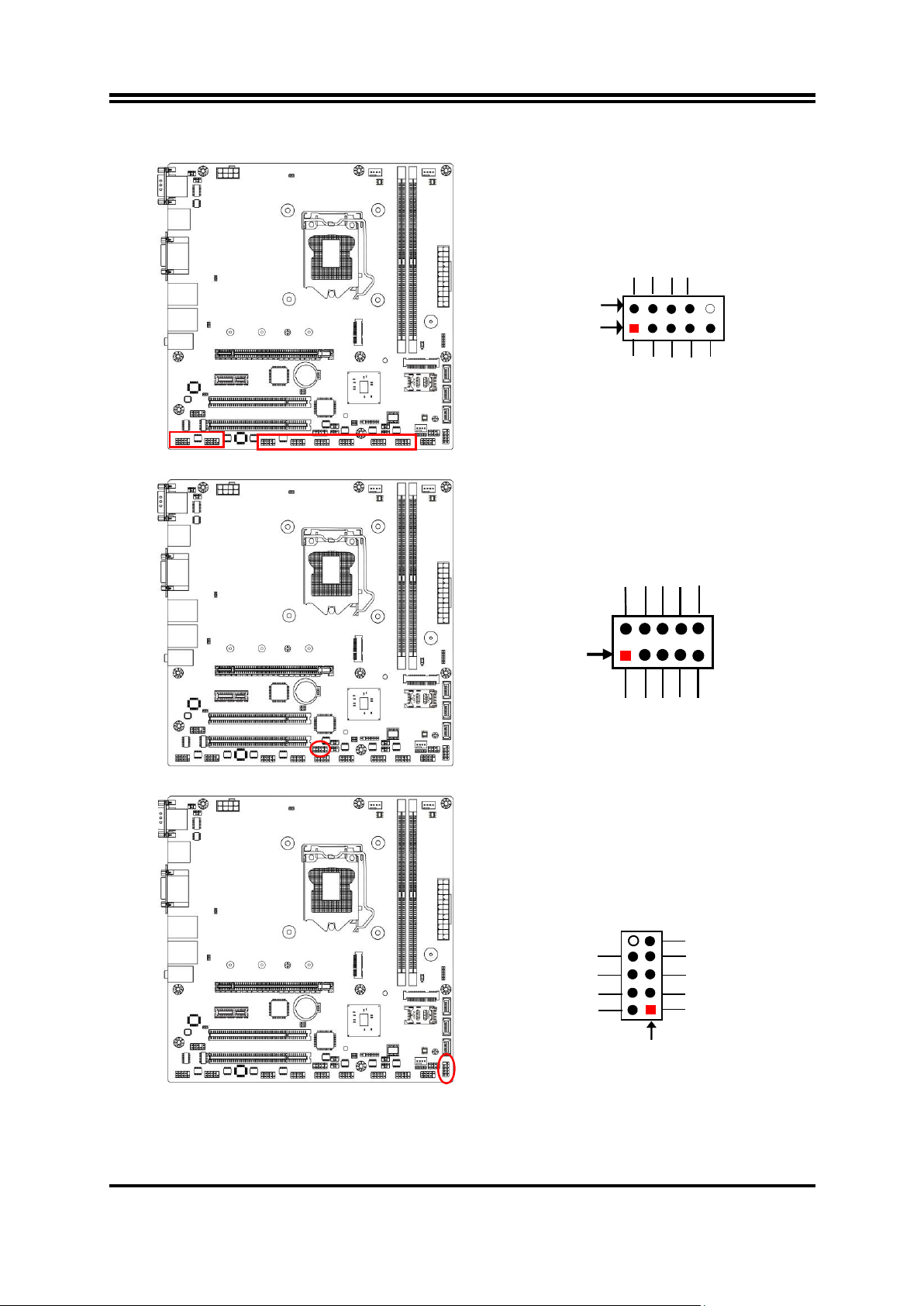
2-2-3 Header Pin Definition
FP_AUDIO (9-pin): Line-Out, MIC-In Header
This header is connected to Front Panel Line-out, MIC connector with cable.
SPDIF (2-pin): HDMI-SPDIF Out header
LAN1_LED/ LAN2_LED (2-pin): LANLED Header
14
Page 19
DCD
Pin1
Pin6
SIN
SOUT
DTR
GND
DSR
RTS
CTS
RI
9
GPIO81
GND
GPIO83
GPIO85
GPIO87
GPIO80
GPIO82
2
Pin 1
10
VCC
GPIO84
GPIO86
HDD LED+
GND
HDD LED-
GND
RSTSW
PWRBTN
Pin 1
2
VCC
PWR LED+
PWR LED -
COM10/9/8/76/5/4/3 (9-pin): Serial Port Header
GPIO_CON (10-pin): GPIO Header
JW_FP (9-pin): Front Panel Header
15
Page 20
Pin 1
PWRLED+
SPEAK+
NC
SPEAK-
NC
PWRLED-
PWRLED
-
Pin 1
VCC
-DATA
GND
+DATA
VCC
NC
-DATA
GND
+DATA
Pin 1
VCC
-DATA
GND
+DATA
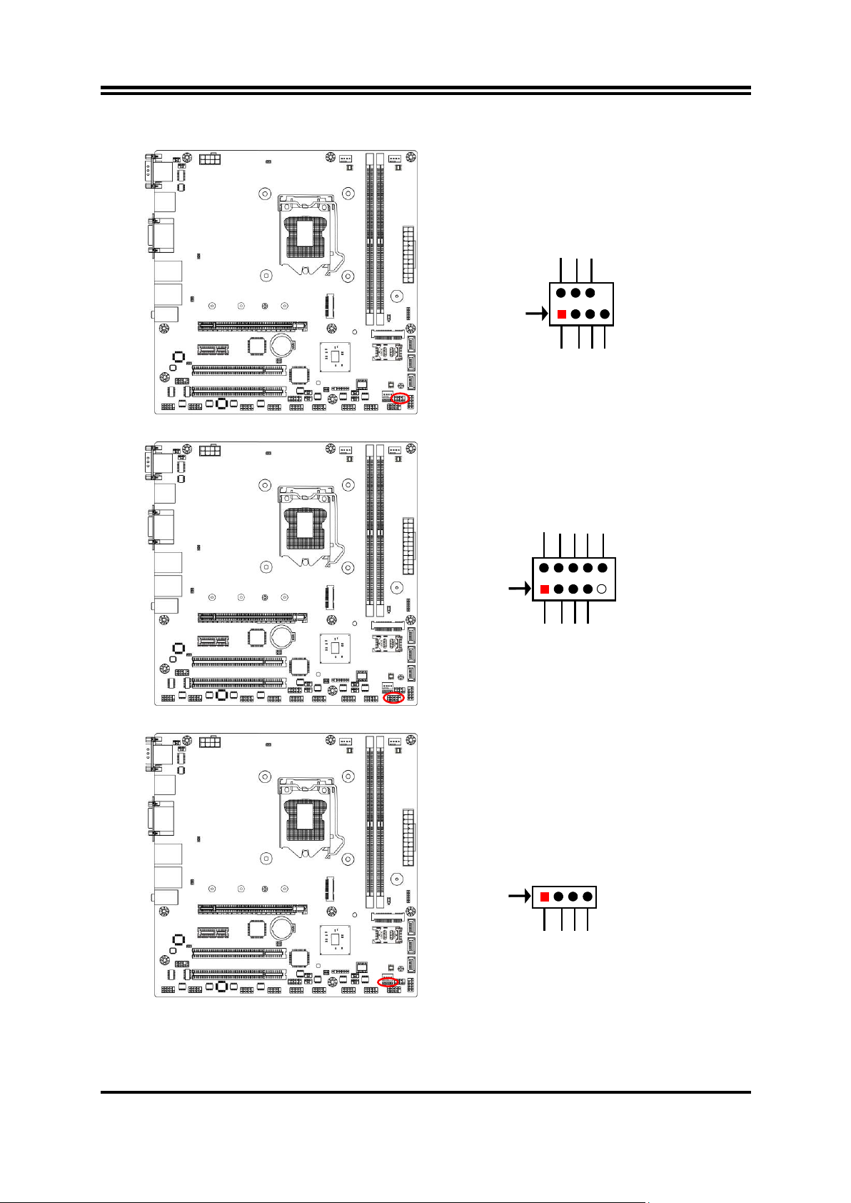
SPK_LED (7-pin): PWR LED Header & Speaker Header
FP_USB1(9-pin): USB 2.0 Port Headers
FP_USB2 (4-pin): USB 2.0 Port Header
16
Page 21
GND
KB_CLK
KB_DATA
Pin1
MS_DATA
VCC
MS_CLK
SMBUS_DATA
Pin1
GND
SMBUS_CLK
SMBUS_ALERT
VCC
Pin1
GND
+12V Fan Power
Fan Speed
Control
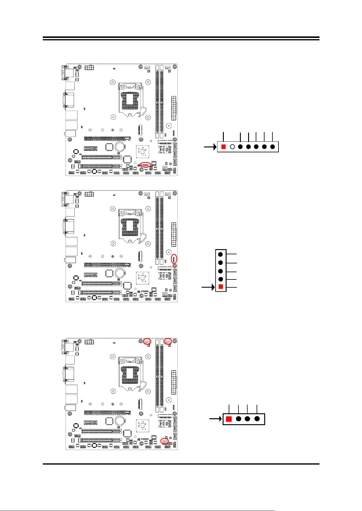
PS2KBMS (6-pin): PS/2 Keyboard & Mouse Header
SMBUS (5-pin): SM BUS Header
SYSFAN1/CPUFAN/SYSFAN2 (4-pin): FAN Headers
17
Page 22
config
Slot 1
Slot 2
1
install
-- 2 --
install
3
install
install
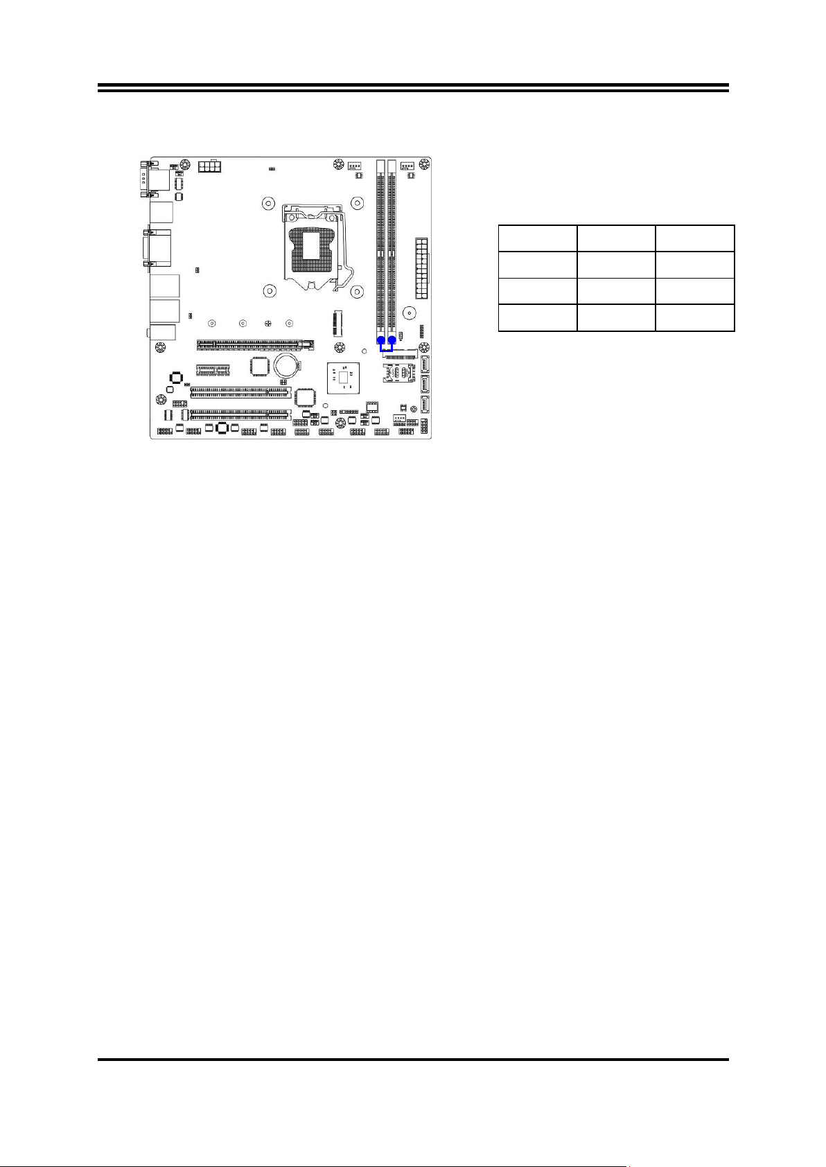
Dual Channel Memory Installation
Notice!
For dual channel installation, you need to install the same brand, speed, size and
type memory module.
It is unable to acti vate dual channel feat ure if y ou install only one memory module.
Slot order can be from left-to-right or right-to-left, and it must be installed in pairs.
If you install memory modules in wrong direction, it will damage the motherboard
and memory module.
18
Page 23

Chapter 3
Introducing BIOS
Notice! The BIOS options in this manual are for reference only. Different
configurations may lead to difference in BIOS screen and BIOS
screens in manuals are usually the first BIOS version when the board
is released and may be different from your purchased motherboard.
Users are welcome to download the latest BIOS version form our
official website.
The BIOS is a pr ogr am loc ated on a F las h Me mory on the mot herbo ard. This prog r am
is a bridge between motherboard and operati ng system. When you start the computer,
the BIOS program will gain control. The BIOS first operates an auto-diagnostic test
called POST (power on self test) for all the necessary hardware, it detects the entire
hardware device and configures the parameters of the hardware synchronization.
Only when these tasks are completed done it gives up control of the computer to
operating sys tem (O S). Since the BIOS is the only channel for hardware and soft ware
to communicate, it is the key factor for system stability, and in ensuring that your
system performance as its best.
3-1 Entering Setup
Power on the c omput er and by pressi ng < Del> immedi atel y allow s y ou to enter Set up .
If the message disappears before your respond and you still wish to enter Setup,
restart the system to try again by turning it OFF then ON or pressing the “RESET”
button on the system case. You may also restart by simultaneously pressing <Ctrl>,
<Alt> and <Delete> keys. If you do not press the keys at the correct time and the
system does not boot, an err or messag e w il l be displ ay ed and y ou w ill agai n be ask e d
to
Press <Del> to enter Setup
3-2 BIOS Menu Screen
The following diagram show a general BIOS m enu screen:
19
Page 24
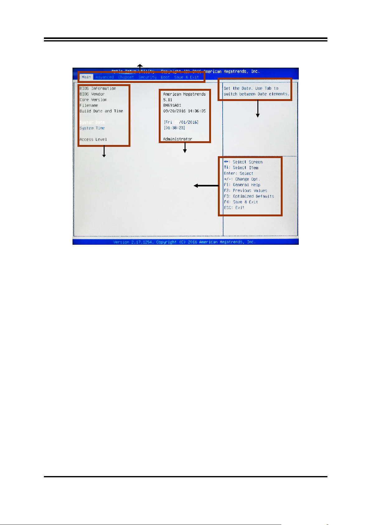
Menu Bar
Menu Items
Current Setting Value
Function Keys
General Help Items
BIOS Menu Screen
3-3 Function Keys
In the above BIOS Setup main menu of, you can see several options. We will explain
these options step by step in the following pages of this chapter, but let us first see a
short description of the function keys you may use here:
Press←→ (left, right) t o select screen;
Press ↑↓ (up, down) to choose, in the main menu, the option you want to confirm
or to modify.
Press <Enter> to select.
Press <+>/<–> keys when you want to modify the BIOS parameters for the active
option.
[F1]: General help.
[F2]: Previous values.
[F3]: Optimized default s .
[F4]: Save & Exit.
Press <Esc> to exit from BIOS Setup.
3-4 Getting Help
Main Menu
The on-line description of the highlighted setup function is displayed at the t op right
corner the screen.
20
Page 25
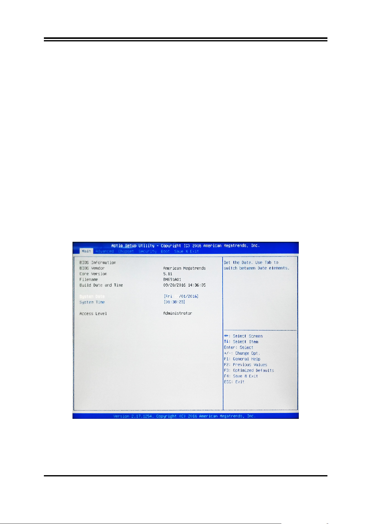
Main
To change system basic configuration
Advanced
To change system advanced configuration
Chipset
To change chipset configuration
Security
Password settings
Boot
To change boot settings
Save & Exit
Save setting, loading and exit options.
Status Page Setup Menu/Option Page Setup Menu
Press 【F1】 to pop up a small help window that desc ribes the appr opriat e keys to us e
and the possible selections for the highlighted item. To exit the Help Window, press
<Esc>.
3-5 Menu Bars
There are six menu bars on top of BIOS screen:
User can press the right or left arrow key on the keyboard to switch from m enu bar.
The selected one is highlighted.
3-6 Main Menu
Main menu screen includes some basic system information. Highlight the item and
then use the <+> or <-> and numerical keyboard keys to select the value you want in
each item.
System Date
Set the date. Please use [Tab] to switch between data elements.
System Time
Set the time. Please use [Tab] to switch between time elements.
21
Page 26
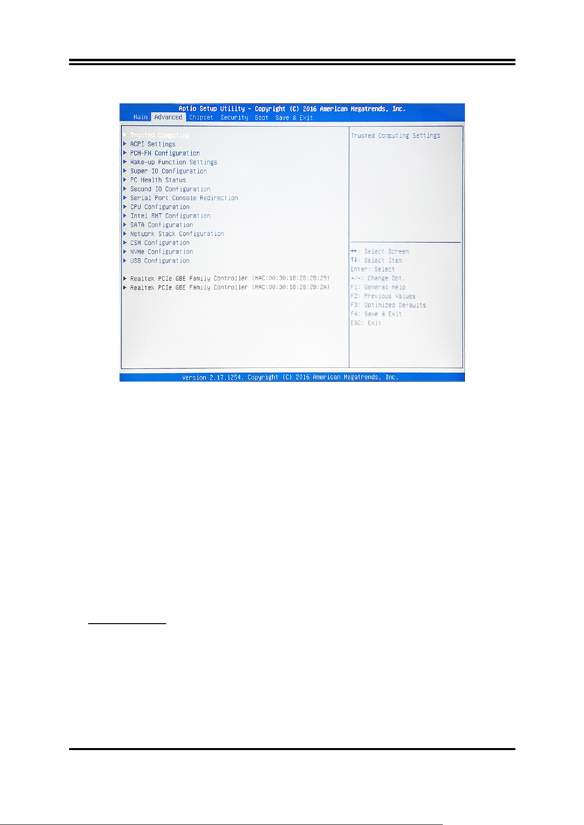
3-7 Advanced Menu
► Trusted Computing
Press [Enter] to enable or disable ‘Security Device Support’.
Security Device Support
Use this item to enable or disable BIOS support for security device.
The optional settings: [Disabled]; [Enabled].
*When set as [Enabled], user can make further settings in the following items:
TPM State
Use this item to enable or disable security device. Your computer will reboot
during restart to change state of device.
The optional settings: [Disabled]; [Enabled].
Pending Operation
Use this item to schedule an operation for the security device. Your computer will
reboot during restart to change state of device.
The optional settings: [None]; [TPM Clear].
► ACPI Settings
Press [Enter] to make setti ng s for t he fol lowing sub-items:
ACPI Settings
ACPI Sleep State
Use this item to sel ect the highest ACPI sleep state t h e system will enter when the
suspend button is pressed.
The optional settings are: [Suspend Disabled]; [S3 (Suspend to RAM)].
► PCH-FW Configuration
Press [Enter] to view ME information and make setti ng s i n the following sub-items:
TPM Device Selection
Use this item to select T PM device.
22
Page 27

The default setting is : [PTT].
[PTT]: Enable PTT in SkuMgr.
► Firmware Update Configuration
Press [Enter] to make setti ng s for ‘ME FW Image RE-Flash’.
ME FW Image Re-Flash
Use this item to enable or disable ME FW Image Re-Flash function.
The optional settings: [Disabled]; [Enabled].
* In the case that user needs to update ME firmware, user should set ‘ME FW
Image Re-Flash’ as [Enabled], save the settings and exit . The s ys t em will turn off
and reboot after 4 seconds. If the user go es to BIOS scr een agai n wil l find this item
is set again as [Disabled], but user can still re-flash to update firmware next time.
► Wake-up Function Settings
Press [Enter] to make setti ng s for t he fol lowing sub-items:
Wake-up System with Fixed Time
Use this item to enable or disable system wake on alarm event.
The optional settings: [Disabled]; [Enabled].
When set as [Enabled], system will wake on the hour/min/sec specified.
Wake-up System with Dynamic Time
Use this item to enable or disable system wake on alarm event.
System will wake on the current time + Increase minutes.
The optional settings: [Disabled]; [Enabled].
When set as [Enabled], system will wake on the current time + increased
minute(s).
PS2 KB/MS Wake-up
The optional settings: [Enabled]; [Disabled].
Use this item to enable or disable PS2 KB/MS wake-up from S3/S4/S5.
* Note: This function is supported when ‘ERP Support’ is set as [Disabled].
USB S3/S4 Wake-up
Use this item to enable or disable USB S3/S4 wakeup. This function is only
supported when ERP function is disabled.
* Note: This function is supported when ‘ERP Support’ is set as [Disabled].
USB S5 Power
Use this item to enable or disable USB power after power shutdown.
*This function is supported when ‘ERP Support ’ is set as [Disabled].
Ring Wake-up
The optional settings: [Enabled]; [Disabled].
Use this item to enable or disable ring wake-up.
* Note: This function is supported when ‘ERP Support’ is set as [Disabled].
► Super I/O Configuration
Press [Enter] to make setti ng s for t he fol lowing sub-items:
Super IO Configuration
ERP Support
The optional settings: [Disabled]; [Auto].
This item should be set as [Disabled] if you wish to have all active wake-up
functions.
23
Page 28

► Serial Port 1 Configuration
Press [Enter] to make settings for the fol l owin g items:
Serial Port
Use this item to enable or disable serial port (COM).
Change Settings
Use this item to select an optimal setting for super IO device.
Transmission Mode Select
The optional settings are: [RS422]; [RS232]; [RS485].
Mode Speed Select
The optional settings are: [RS232/RS422/RS485=250kbps]; [RS232=1Mbps,
RS422/RS485=10Mbps].
Serial Port FIF0 Mode
The optional setting s are: [16-Byte FIF0]; [32-Byte FIF0]; [64-Byte FIF0]; [128-Byte
FIF0].
► Serial Port 2 Configuration/ Serial Port 3 Configuration/Serial Port 4
Configuration/ Serial Port 5 Configuration/ Serial Port 6 Configuration
Press [Enter] to make settings for the fol l owing sub-items:
Serial Port
Use this item to enable or disable serial port (COM).
Change Settings
Use this item to select an optimal setting for super IO device.
Serial Port FIF0 Mode
The optional setting s are: [16-Byte FIF0]; [32-Byte FIF0]; [64-Byte FIF0]; [128-Byte
FIF0].
WatchDog Reset Timer
Use this item to enable or disable WDT reset function. When set as [Enabled], th e
following sub-items shall appear:
WatchDog Reset Timer Value
User can set a value in the range of [4] to [255].
WatchDog Reset Timer Unit
The optional settings are: [Sec.]; [Min.].
WatchDog Wake-up Timer in ERP
This item support WDT wake-up while ‘ERP Support’ is set as [Auto].
The optional settings: [Disabled]; [Enabled].
When set as [Enabled], the following sub-items shall appear:
WatchDog Wake-up Timer Value in ERP
User can select a value in the range of [10] to [4095] seconds when ‘WatchDog
Reset Timer Unit’ set as [Sec]; or in the range of [1] to [4095] minutes when
‘WatchDog Reset Timer Unit ’ set as [Min].
WatchDog Reset Timer Unit
The optional settings are: [Sec.]; [Min.].
ATX Power Emulate AT Power
This item support Emulate AT power function, MB power On/Off control by power
supply. Use needs to select ‘AT or ATX Mode’ on MB jumper at first (refer to Page
8, Pin(1-2) of AT_COPEN jumper for ATX Mode & AT Mode Select).
Case Open Detect
Use this item to detect case has already open or not, show message in POST.
24
Page 29

PS2 KB/MS Connect
The optional settings are: [Keyboard First]; [Mouse First].
► PC Health Status
Press [Enter] to view current hardware health status, make further settings in
‘SmartFAN Configuration’ and set value in ‘Shutdown Temperature’.
► SmartFAN Configuration
Press [Enter] to make setti ng s for S mar tFan Configuration:
SmartFAN Configuration
CPUFAN / SYSFAN1/ SYSFAN2 Smart Mode
The optional settings are: [Disabled]; [Enabled].
When set a s [Enabled], the following sub-items shall appear:
CPUFAN / SYSFAN1/ SYSFAN2 Full-Speed Temperature
Use this item to set CPUFAN /SYSFAN1/SYSFAN2 full speed temperature. Fan
will run at full speed when above this pre-set temperature.
CPUFAN / SYSFAN1/ SYSFAN2 Full-Speed Duty
Use this item to set CPUFAN /SYSFAN1/SYSFAN2 full-speed duty. Fan will run at
full speed when above this pre-set duty.
CPUFAN / SYSFAN1/ SYSFAN2 Idle-Speed Temperature
Use this item to set CPUFAN /SYSFAN1/SYSFAN2 idle speed temperature. Fan
will run at idle speed when below this pre-set temperature.
CPUFAN / SYSFAN1/ SYSFAN2 Idle-Speed Duty
Use this item to set CPUFAN /SYSFAN1/SYSFAN2 idle speed duty. Fan will run
at idle speed when below this pre-set duty.
Shutdown Temperature
Use this item to select system shutdown temperature.
The optional settings are: [Disabled]; [70oC/156oF]; [75oC/164oF]; [80oC/172oF];
[85oC/180oF]; [90oC/188oF].
Second IO Configuration
Press [Enter] to make setti ng s for t he fol lowing sub-items:
Second IO Configuration
► Serial Port 7 Configuration/ Serial Port 8 Configuration/Serial Port 9
Configuration/ Serial Port 10 Configuration
Press [Enter] to make settings for the fol l owing sub-items:
Serial Port
Use this item to enable or disable serial port (COM).
Change Settings
Use this item to select an optimal setting for super IO device.
Serial Port Console Redirection
COM1
Console Redirection
Use this item to enable or disable COM1 Console Redirection.
The optional settings are: [Disabled]; [Enabled].
When set as [Enabled], user can make further settings in the ‘Console
Redirection Settings’ screen:
Console Redirection Settings
25
Page 30

The settings specify how the host computer and the remote computer (which the
user is using) will exchange data. Both computers should have the same or
compatible settings.
Press [Enter] to make settings for the fol l owing sub-items.
Terminal Type
The optional settings are: [VT100]; [VT100+]; [VT-UTF8]; [ANSI].
Bits per second
The optional settings are: [9600]; [19200]; [38400]; [57600]; [115200].
Data Bits
The optional settings are: [7]; [8].
Parity
The optional settings are: [None]; [Even]; [Odd];[Mark]; [Space].
Stop Bits
The optional settings are: [1]; [2].
Flow Control
The optional settings are: [None]; [Hardware RTS/CTS].
VT-UTF8 Combo Key Support
The optional settings are: [Disabled]; [Enabled].
Recorder Mode
The optional settings are: [Disabled]; [Enabled].
Resolution 100x31
The optional settings are:[Disabled]; [Enabled].
Legacy OS Redirection Resolution
The optional settings are: [80x24]; [80x25].
Putty Keypad
The optional settings are: [VT100]; [LINUX]; [XTERMR6]; [SCO]; [ESCN];
[VT400].
Redirection After BIOS POST
The optional settings are: [Always Enable]; [BootLoader].
Serial Port for Out-of-Band Management/
Windows Emergency Management Services (EMS)
Console Redirection
The optional settings: [Disabled]; [Enabled].
When set as [Enabled], user can make further settings in ‘Console
Redirection Settings’ screen:
Console Redirection Settings
The settings specify how the host computer and the remote computer (which the
user is using) will exchange data. Both computers should have the same or
compatible settings.
Press [Enter] to make setti ng s for t he fol lowing sub-items.
Out-of-Band Mgmt Port
The optional sett ings ar e: [COM1]; [COM1(Pci Bus 0, D ev0, Func 0) ( Di sabled) ].
Terminal Type
The optional settings are: [VT100]; [VT100+]; [VT-UTF8]; [ANSI].
Bits per second
The optional settings are: [9600]; [19200]; [57600]; [115200].
Flow Control
The optional settings are: [None]; [Hardware RTS/CTS]; [Software Xon/Xoff].
26
Page 31

Data Bits
The default setting is: [8].
*This item may or may not show up, depending on different configuration.
Parity
The default setting is: [None].
*This item may or may not show up, depending on different configuration.
Stop Bits
The default setting is: [1].
*This item may or may not show up, depending on different configuration.
► CPU Configuration
Press [Enter] to view current CPU configuration and make settings for the
following sub-items:
Hyper-Threading
The optional settings: [Disabled]; [Enabled].
When set a s [Disabled] only one thread per enabled core is enabled.
[Enabled]: for Windows XP and Linux (OS optimized for Hyper-Threading
Technology).
[Disabled]: for other OS (OS optimized not for Hyper-Threading Technology ) .
*Note: ‘Hyper-Threading’ item may or may not show up, depending on different
CPU.
Intel Virtualization Technology
The optional settings: [Enabled]; [Disabled].
When set as [Enabled], a VMM can utilize the additional hardware capabilities
provided by Vanderpool Technology.
Hardware Prefetcher
Use this item to turn on/off the MLC streamer prefecher.
The optional settings: [Disabled]; [Enabled].
Adjacent Cache Line Prefetch
Use this item to turn on/off prefeching of adjacent cache lines.
The optional settings: [Disabled]; [Enabled].
Intel(R) SpeedStep(tm)
This item allows more than two frequency ranges to be supported.
The optional settings: [Disabled]; [Enabled].
CPU C Status
Use this item to enable or disable CPU C status.
The optional settings: [Disabled]; [Enabled].
Package C State Limit
The optional settings are: [C0/C1]; [C2]; [C3]; [C6]; [C7]; [C7s]; [C8]; [AUTO].
► Intel RMT Configuration
Press [Enter] to go to next screen to enable or disable ‘Intel Ready Mode
Technology’.
Intel Ready Mode Technology
The optional settings: [Disabled]; [Enabled].
*When set as [Enabled], user can also make fur ther settings in the following it ems
that appear:
Intel RMT State
Use this item to enable or disable Intel RMT enabling status in BIOS.
27
Page 32

► SATA Configuration
Press [Enter] to make setti ng s for t he fol lowing sub-items:
SATA Controller(s)
The optional settings: [Disabled]; [Enabled].
SATA Mode Selection
The default setting is: [AHCI].
SATA1/ SATA2/SATA3
Port
The optional settings: [Disabled]; [Enabled].
Use this item to enable or disable each SATA port.
Hot Plug
The optional settings: [Disabled]; [Enabled].
M.2
Port
The optional settings: [Disabled]; [Enabled].
Use this item to enable or disable device connected to M.2 SATA slot.
► Network S t ack Configuration
Press [Enter] to go to ‘Network Stack’ screen to make further settings.
Network S t ack
Use this item to enable or disable UEFI Network Stack.
The optional settings: [Disabled]; [Enabled].
When set a s [Enabled], the following sub-items shall appear:
Ipv4 PXE Support
The optional settings are: [Disabled]; [Enabled].
Use this item to enable Ipv4 PXE Boot Support. When set as [Disabled], Ipv4 boot
option will not be created.
Ipv6 PXE Support
The optional settings are: [Disabled]; [Enabled].
Use this item to enable Ipv6 PXE Boot Support. When set as [Disabled], Ipv6 boot
optional will not be created.
PXE boot wait time
Use this item to set wait time to press [ESC] key to abort the PXE boot.
Media Detect Count
Use this item to set number of times presence of media will be checked.
► CSM Configuration
Press [Enter] to m ake settings for the following sub-items:
Option ROM execution
Network
This option controls the execution of UEFI and Legacy PXE OpROM.
The optional settings are: [Do not launch]; [UEFI]; [Le gacy].
Storage
This option controls the execution of UEFI and Legacy Storage OpROM.
The optional settings are: [Do not launch]; [UEFI]; [Le gacy].
Other PCI devices
This item is for PCI devices other than Network, Mass storage or video defines
which OpROM to launch.
The optional settings are: [Do not launch]; [UEFI]; [Legacy].
28
Page 33

► NVMe Configuration
Press [Enter] to check NVMe controller and driver information.
► USB Configuration
Press [Enter] to make setti ng s for t he fol lowing sub-items:
USB Configuration
Legacy USB Support
The optional settings are: [Enabled]; [Disabled]; [Auto].
[Enabled]: To enable legacy USB support.
[Disabled]: to keep USB devices available only for EFI specification,
[Auto]: To disable legacy support if no USB devices are connected.
XHCI Hand-off
This is a workaround for OSes without XHCI hand-off support. The XHCI
ownership change should be claimed by XHCI driver.
The optional settings are: [Enabled]; [Disabled].
USB Mass Storage Driver Support
The optional settings are: [Disabled]; [Enabled].
USB hardware delay and time-out
USB Transfer time-out
Use this item to set the time-out value for control, bulk, and interrupt transfers.
The optional settings are: [1 sec]; [5 sec]; [10 sec]; [20 sec].
Device reset time-out
Use this item to set USB mass storage device start unit command time-out.
The optio nal settings are: [10 sec]; [20 sec]; [30 sec]; [40 sec].
Device power-up delay
Use this item to set maximum time the device will take before it properly reports
itself to the host contro l ler . ‘Auto’ uses default v al ue: for a root port it is 100 ms, for
a hub port the delay is taken from hub descriptor. The optional settings: [Auto];
[Manual].Select [Manual] you can set value for the following sub-item: ‘Device
Power-up delay in seconds’, the delay range in from 1 to 40 seconds, in one
second increments.
► Realtek PCIe GBE Family Controller(MAC:XX:XX:XX:XX:XX:XX)/ Realtek
PCIe GBE Family Controller(MAC:XX:XX:XX:XX:XX:XX)
These items show current network brief information.
29
Page 34
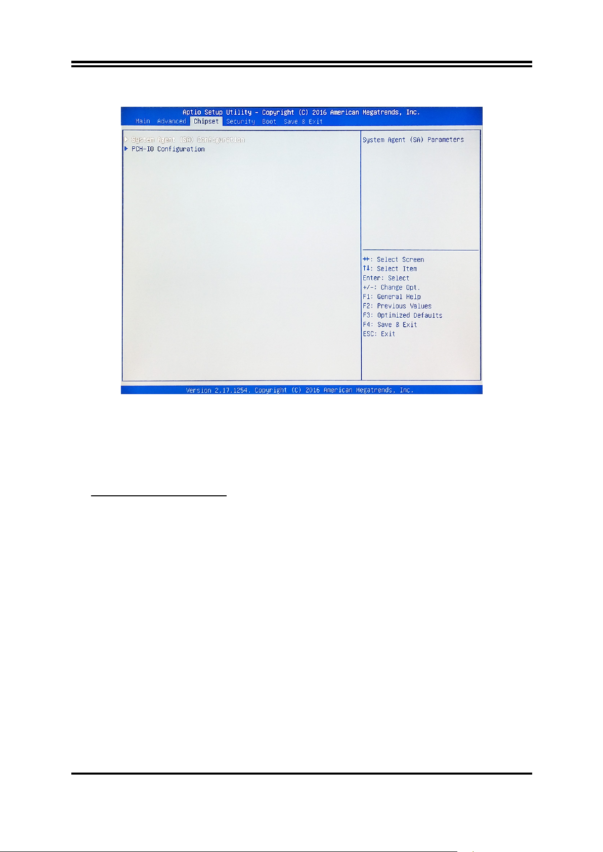
3-8 Chipset Menu
► System Agent (SA) Configuration
Press [Enter] to make settings for the fol l owing sub-items:
VT-d
The optional settings are: [Enabled]; [Disabled].
► Graphics Configuration
Press [Enter] to make further settings for Graphics Configuration.
Graphics Configuration
Primary Display
Use this item to select which of graphics device should be primary display.
The optional settings are: [Auto]; [IGFX]; [PEG].
Internal Graphics
The optional settings are: [Auto]; [Disabled]; [ Enabled].
GTT Size
The optional settings are: [2MB]; [4MB]; [8MB].
Aperture Size
The optional settings are: [128MB]; [256MB]; [512MB]; [1024MB].
DVMT Pre-Allocated
Use this item to select DVMT 5.0 pre-allocated (fixed) graphics memory size used
by the internal graphics device.
The optional settings are: [32M]; [64M]; [96M]; [128M]; [160M]; [192M]; [224M];
[256M]; [288M]; [320M]; [352M]; [384M]; [416M]; [448M]; [480M]; [512M]; [1024M] ;
[1536M] ; [2048M] ; [4M] ; [8M] ; [12M] ; [16M] ; [20M]; [24M] ; [28M] ; [32M/F7] ;
[36M]; [40M]; [44M]; [48M]; [52M]; [56M]; [60M].
DVMT Total Gfx Mem
Use this item to select DVMT 5.0 total graphics memory size used by the internal
graphics device.
30
Page 35

The optional settings are: [128M]; [256M]; [MAX].
Primary IGFX Boot Display
Use this item to select the video device which will be activated during POST. This
has no effect if external graphics present. Secondary boot display selection will
appear based on your selection.
The optional settings are: [VBIOS Default]; [HDMI]; [DVI]; [CRT].
* Note: When set as [HDMI], [DVI] or [CRT], user can make further settings in
‘Second IGFX Boot Display’.
Second IGFX Boot Display
Use this item to select second IGFX boot device..
The optional settings are: [Disabled]; [HDMI]; [DVI]; [CRT].
► PEG Port Configuration
Press [Enter] to make settings for the fol l owing sub-items:
PEG Port Configuration
PEG(PCIE1 Slot)
This will show current device connected to PCIE1 slot.
Max Link Speed
The optional settings are: [Auto]; [Gen1]; [Gen2]; [Gen3].
► Memory Configuration
Press [Enter] to view brief information for the working memory module.
► PCH-IO Configuration
Press [Enter] to make settings for the fol l owing sub-items:
USB Controller
The optional settings are: [Disabled]; [Enabled].
HD Audio
The optional settings are: [Disabled]; [Enabled]; [Auto].
Onboard Lan1 Controller/ Onboard Lan2 Controller
Use this item to enable or disable LAN1/LAN2 device or controller.
PCIE2 Slot
Use this item to enable or disable the PCI Express Root Port.
The optional settings are: [Disabled]; [Enabled].
Speed
The optional settings are: [Auto]; [Gen1]; [Gen2]; [Gen3].
MPE Slot
Use this item to enable or disable the PCI Express root port.
The optional settings are: [Disabled]; [Enabled].
Speed
The optional settings are: [Auto]; [Gen1]; [Gen2]; [Gen3].
System State after Power Failure
Use this item to specify what state to go to when power re-applied after a power
failure (G3 state).
The optional settings are: [Always Off]; [Always On]; [Former State].
31
Page 36
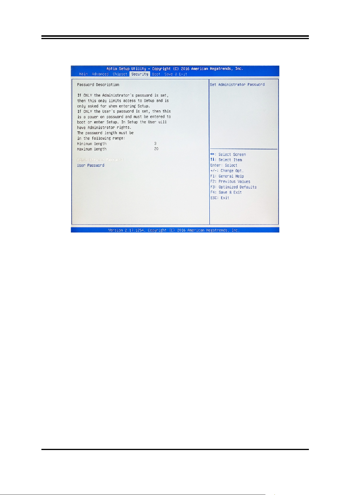
3-9 Security Menu
Security menu allow users to change administrator password and user password
settings.
Administrator Password
Press [Enter] to create new administrator password. Press again to confirm the new
administrator password.
User Password
Press [Enter] to create new user password. Press again to confirm the new user
password.
32
Page 37
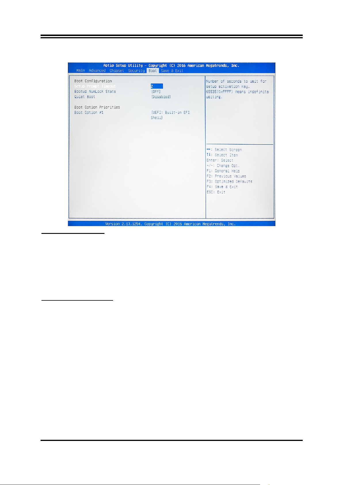
3-10 Boot Menu
Boot Configuration
Setup Prompt Timeout
Use this item to set number of seconds to wait for setup activation key.
Bootup Numlock State
Use this item to select keyboard numlock state.
The optional settings are: [On]; [Off].
Quiet Boot
The optional settings are: [Disabled]; [Enabled].
Boot Option Priorities
Boot Option #1/ Boot Option #2…
Use this item to decide system boot order from available options.
33
Page 38
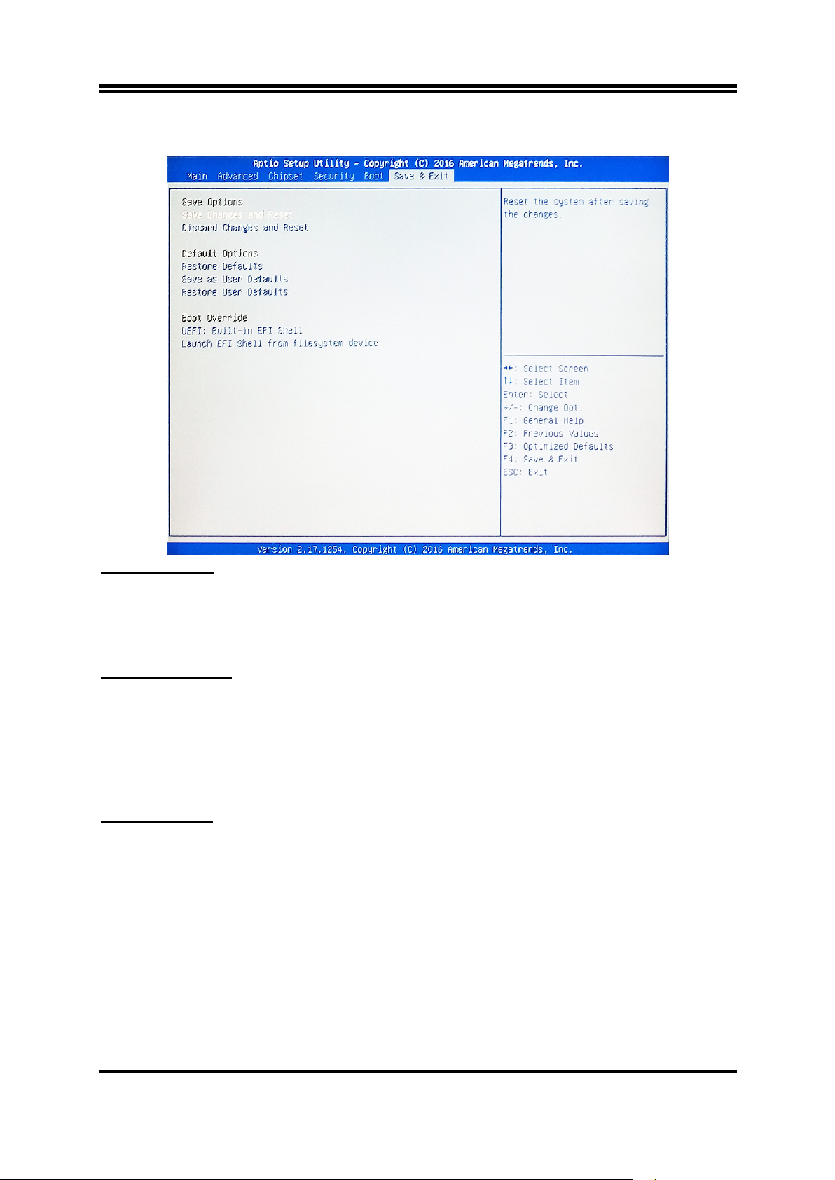
3-11 Save & Exit Menu
Save Options:
Save Changes and Reset
This item allows user to reset the system after saving the changes.
Discard Changes and Reset
This item allows user to reset the system without saving any changes.
Default Options:
Restore Defaults
Use this item to restore /load default values for all the setup options.
Save as User Defaults
Use this item to save the changes done so far as user defaults.
Restore User Defaults
Use this item to restore defaults to all the setup options.
Boot Override
UEFI:xx/…
Press this item to select the device as boot disk after save configuration and reset
Launch EFI Shell from filesystem device
Press this item to launch EFI Shell application (Shell.efi) from one of the available file
system device.
34
 Loading...