

Page 1

Operating Instructions and Parts Manual
24-in ch Pneu mat ic Planishing Hammer
Model PH-24T
WALTER MEIER (Manuf acturing) Inc.
427 New Sanford Road
LaVergne, Tennessee 37086 Part No. M- 756121
Ph.: 800-274-6848 Revision A 05/2011
www.walt er meier.c om Copyright © 2011 Walt er Meier (M anufacturi ng) Inc.
Page 2

W arranty and Service
Walter Meier (Manufacturing) Inc., warrants every product it sells. If one of our tools needs service or repair, one of
our Authorized Service Centers located throughout the United States can give you quick service. In most cases, any
of these Walter Meier Authorized Service Centers can authorize warranty repair, assist you in obtaining parts, or
®
perform routine maintenance and major repair on your JET
your area call 1-800-274-6848.
MORE INFORMATION
Walter Meier is consistently adding new products to the line. For complete, up-to-date product information, check with
your local Walter Meier distributor, or visit waltermeier.com.
WARRANTY
JET products carry a limited warranty which varies in duratio n based upon the product (MW = Metalworking, WW =
Woodworking).
WHAT IS COVERED?
This warranty covers any defects in workmanship or materials subject to the e xceptions stated below. Cutting tools,
abrasives and other consumables are excluded from warranty coverage.
WHO IS COVERED?
This warranty covers only the initial purchaser of the product.
WHAT IS THE PERIOD OF COVERAGE?
The general JET warranty lasts for the time period specified in the product literature of each product.
WHAT IS NOT COVERED?
Five Year Warranties do not cover woodworking (WW) products used for commercial, industrial or educational
purposes. Woodworking products with Five Year Warranties that are used for commercial, industrial or education
purposes revert to a One Year Warranty. This warranty does not cover defects due directly or indirectly to misuse,
abuse, negligence or accidents, normal wear-and-tear, improper repair or alterations, or lack of maintenance.
HOW TO GET SERVICE
The product or part must be returned for examination, postage prepaid, to a location designated by us. For the name
of the location nearest you, please call 1-800-274-6848.
You must provide proof of initial purchase date and an explanation of the complaint must accompany the
merchandise. If our inspection discloses a defect, we will repair or replace the product, or refund the purchase price,
at our option. We will return the repaired product or replacement at our expense unless it is determined by us that
there is no defect, or that the defect resulted from causes not within the scope of our warranty in which case we will,
at your direction, dispose of or return the product. In the event you choose to have the product returned, you will be
responsible for the shipping and handling costs of the return.
HOW STATE LAW APPLIES
This warranty gives you specific legal rights; you may also have other rights which vary from state to state.
LIMITATIONS ON THIS WARRANTY
WALTER MEIER (MANUFACTURING) INC., LIMITS ALL IMPLIED WARRANTIES TO THE PERIOD OF THE
LIMITED WARRANTY FOR EACH PRODUCT. EXCEPT AS STATED HEREIN, ANY IMPLIED WARRANTIES OR
MERCHANTABILITY AND FITNESS ARE EXCLUDED. SOME ST ATES DO NOT ALLOW LIMITATIONS ON HOW
LONG THE IMPLIED WARRANTY LASTS, SO THE ABOVE LIMITATION MAY NOT APPLY TO YOU.
WALTER MEIER SHALL IN NO EVENT BE LIABLE FOR DEATH, INJURIES TO PERSONS OR PROPERTY, OR
FOR INCIDENTAL, CONTINGENT, SPECIAL, OR CONSEQUENTIAL DAMAGES ARISING FROM THE USE OF
OUR PRODUCTS. SOME STATES DO NOT ALLOW THE EXCLUSION OR LIMITATION OF INCIDENTAL OR
CONSEQUENTIAL DAMAGES, SO THE ABOVE LIMITATION OR EXCLUSION MAY NOT APPLY TO YOU.
Walter Meier sells through distributors only. The specifications in Walter Meier catalogs are given as general
information and are not binding. Members of Walter Meier reserve the right to effect at any time, without prior notice,
those alterations to parts, fittings, and accessory equipment which they may deem necessary for any reason
®
whatsoever. JET
branded products are not sold in Canada by Walter Meier.
tools. For the name of an Authorized Service Center in
2
Page 3

Table of Contents
Warranty and Service..........................................................................................................................2
Table of Contents ...............................................................................................................................3
In trodu ction ........................................................................................................................................3
Specifications for PH-24T Planishing Hammer ......................................................................................6
Features and Terminology ...................................................................................................................7
Unpacking, Mounting and Assembly ....................................................................................................8
Operation ...........................................................................................................................................8
Changing Dies ....................................................................................................................................9
Mai nten ance ......................................................................................................................................9
Assembly Drawing for PH-24T Planishing Hammer ............................................................................. 10
Ordering Replacement Parts ............................................................................................................. 11
Parts List for PH-24T Planishing Hammer .......................................................................................... 11
Introduction
This manual is provided by Walter Meier (Manufacturing) Inc., covering the safe operation and
maintenance pr ocedures for the JET PH-24T Planis hing Ham mer. This ma nual contains i nstr uctio ns on
installation, safety precautions, general operating procedures, maintenance instructions and parts
breakdown. T his mac hine has been designed and constructed to provide years of tr ouble fr ee oper ation if
used in accor dance with i nstr uctions set forth i n t his ma nual. If there are any questio ns or co mments,
please contact eit her your local supplier or Walter Meier. Walter Meier can also be reached at our web
site: www.waltermeier.com.
3
Page 4

1. Read and understand t he entire owner’s manual befor e attempting assembly or operation.
2. Read and understand the war nings post ed on the machine and in this manual. Fa ilure t o comply with
all of these warnings may cause serio us injury.
3. Replace the warning labels if they become obscured or removed.
4. This planishing hammer is designed and intended for use by properly trained and experienced
per sonne l o nly. I f y ou are not fa miliar w it h the proper and safe operation of a planishing hammer, do
not us e unti l proper t r aining and knowledge have been obtained.
5. Do not use t his pl anishing ham m er fo r other than its int ende d use. If used fo r o ther purposes, Walte r
Meier (Manufacturing) I nc., disclaims any r eal or i mp lied w arr anty and holds itse lf harmless from any
injury that may result from that use.
6. Always wear approved safety glasses/face shields while using this planishing hammer. Everyday
eyeglasses only have impact r esist ant lenses; t hey are not safet y glasses.
7. Before operating this planishing hammer, remove tie, rings, watches and other jewelry, and roll
sleeves up past the elbows. Remove all loose clothing and confine long hair. Non-slip footwear or
anti-skid floor str ips are r ecommended.
8. Wear ear pr otect or s (plugs or muffs ) during exte nded periods of oper at ion.
9. Some dust created by power sanding, sawing, grinding, drilling and other construction activities
contain chemicals k nown to cause cancer, birt h defects or ot her reproductive harm. Some e xamples
of these chemicals are:
• Lead from lead based paint.
• Crystalline silica from bricks, cement and ot her masonry products.
• Arsenic and chromium fr om chemically treated lumber.
Your risk of exposure varies, depending on how often you do this type of work. To reduce your
exposure to these chemicals, work in a well-ventilated area and work with approved safety
equipment, such as face or dust masks that are specifically designed to filter out microscopic
particles.
10. Do not operate this machine while tired or under the influence of drugs, alcohol or any medicat io n.
11. Make cer t ain the machine is properly grounded.
12. Make all machine adjustme nts or maintenance with the machine unplugged from the power source.
13. Remove adjusting keys and wrenches. Form a habit of checking to see that keys and adjusting
wrenches are removed from the mac hine before tur ning it on. .
14. Check damaged parts. Before further use of the machine, a guard or ot her part that is damaged
should be carefully checked to determine that it will operate properly and perform its intended
function. Check for alignme nt of moving part s, binding of moving part s, break age of part s, mounting
and any other condit ions t hat may affect its oper ation. A guard or other part that is damaged s hould
be properly repaired or r eplaced.
15. Provide for adequate space surrounding work area and non-glare, overhead lighti ng.
16. Keep the floor around t he machine clean and free of sc r ap material, oil and grease.
17. Don't use i n dangero us e nvironment. Don't use power t ools i n damp or w et locations, or expose t hem
to rain. Keep work ar ea well lighted.
18. Keep visitors a saf e dist ance from the wor k ar ea. Keep children away.
19. Make your workshop child proof with padlocks, master switches or by removing star t er keys.
4
Page 5

20. Give your work undivided att ention. Looking aro und, carrying on a conversat ion and “ horse-play” are
careless acts that can result in serious injury.
21. Do not overreach. Keep proper f oot ing and bala nce at all times.
22. Use the right tool at t he correc t speed and feed rate. Do not force a tool or at t achment to do a jo b f or
which it was not designed. The r ight t o ol will do t he job b e tter a nd mor e s a fely.
23. Use recommended accessor ies; improper acc essor ies may be ha zardo us.
24. Maintain tools with care. Follow instructions for lubricating and c hangi ng accessories.
25. Disconnect tools bef or e ser vicing or cha nging accessor ies.
26. Use leather glo ves when handli ng sheet metal.
27. Keep hands, f ingers and arms away f r om the hammer and anvil during operation.
28. Do not exceed the maximum rat ed air pr essure to the regulator.
29. Disconnect tool f r om air supply when not in use.
30. Turn off t he mac hine bef or e cleaning. Us e a br us h or co mpressed air t o r emo ve c hips or debr is — do
not use your hand s.
31. Do not stand on the machine. Serio us injury co uld occur if the machine tips over.
32. Never lea ve the machine r unni ng unattended. Turn the power off and do not leave the machine until it
comes to a complete stop.
33. Remove loose items a nd unnecessary w or k pieces f r om the area befor e starting the machine.
Familiarize yours elf with the f ollow ing saf et y not ices used in t his manual:
This means that if precautions are not heeded, it may result in minor injury and/or
possible machine damage.
This means that if pr ecautions are not heeded, it may result in serious injury or possibly
even death.
5
Page 6

Specificati ons fo r P H- 24T Plan ishing Hammer
Model ...................................................................................................................................................................PH-24T
Stock Number ...................................................................................................................................................... 756121
Electr ical Power :
Incoming Power ............................................................................................................. 110V, Single-Phase, 60Hz
Controls ........................................................................................................................................... foot pedal , 110V
Power Plug included .............................................................................................................................................yes
Power Cable.......................................................................................................................................... 16AWG, 9 ft.
Foot Pedal Cable Length ....................................................................................................... ....................... 3-1/2 ft.
General Dimensions:
Throat ................................................................................................................................................................... 24”
Head Opening ..................................................................................................................................................2-1/2”
Wheels .................................................................................................................................... 3-1/4” Dia. x 1-1/4” W
Hammer Die ................................................................................................................................................... flat
Anvil Die .................................................................................................................................................... crown
Anvil shaft insert end diameter ....................................................................................................................... 0.079”
Operati on:
Workpiece Max imum Gauge (mild sheet steel) ............................................................................................ 16 ga.
Workpiece Max imum Thickness (aluminum, copper) ....................................................................................... 1/8”
Air Intake Connector ................................................................................................................................... 1/4” NPT
Air Regulator ................................................................................................................ 3-position (3 sp eed ranges)
Blows per Minute .......................................................................................... 4400-4600 / 3200-35 00 / 1800-2000
Maximum Pounds per Hit ...................................................................................................................................... 45
Air Pressure Required ........................................................................................... 90-120 PSI (6.33-8. 47 kg/cm
Air Consumption ............................................................................................................... .......................... 8.8 CFM
Noise Level .................................................................................................................... ................92.26 to 104.3 dB
Lubric atio n req uire d .............................................................................................. L ubric ato r cup, ISO32/SAE10W
Construction:
Frame .................................................................................................. welded and gu sseted – 0.137” steel t ubing
Frame Tube size .............................................................................................................................................. 4” x 4”
Support Tube size............................................................................................................................................ 3” x 2”
Handwheels .................................................................................................................................. polished cast iron
Other:
Shipping Weight ............................................................................................................................................ 250 lbs.
Net Weight..................................................................................................................................................... 220 lb s.
Overall Dimensions, shipping ............................................................................ 36-1/4” L x 14-3/5” W x 67-3/ 4” H
Overall Dimensions, fully assembled ................................................................................... 34” L x 29” W x 66” H
The specifications in this manual are given as general information and are not binding. The above
specificati ons were current at the time this manual was published, but because of our policy of continuous
improvement, Walter Meier reserves the right to effect, at any time and without prior notice, changes or
alterations to parts, fittings, and accessory equipment deemed necessary for any reason whatsoever.
Ø2”
R2”
2
)
Read and understand the entire contents of this manual before attempting
assembly or operation! Failure to comply may cause serious injury!
6
Page 7
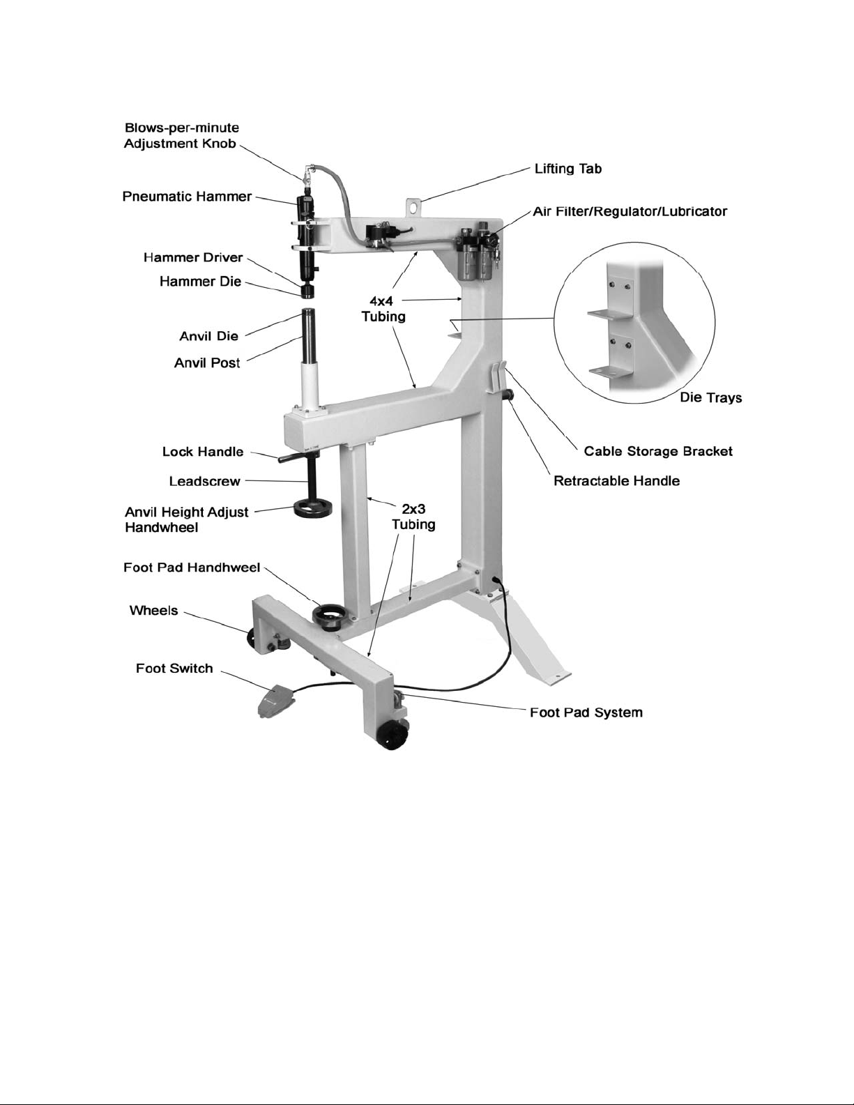
Features and T erminology
Figure 1 - Features
7
Page 8

Unp acking, M ou nting and Assembly
1. With the help of an assistant, carefully
uncrate the planishing hammer. A tab is
welded to t he top t ube if yo u choose t o use
a hoist to set up the machine.
2. Determine the most suitable location for
your planishing hammer based on the
planned usage of the machine. Larger
workpieces require a larger space around
t he pl anishing ham m er .
3. Mount any loose items to the frame, such as
the die tray s, using the photo on page 7 and
the breakdown on page 10 as guides.
4. Lowe r the foot pads to contact the floor, using
t he handw heel.
5. Secure the planishing hammer to the floor
using fasteners (not included) appropr iate for
the floor type. These are inserted t hrough the
holes on the frame’s back leg.
Referring to Figure 2:
6. Attach the pneum atic ham mer to the frame
with the upper clamp (has rounded notch)
and lower clamp. Secure the clamps with
four M6x25 socket head c ap scr ews and M6
lock washers.
Operation
Keep hand s clear of ham mer
and anvil area at all ti mes! Failure to co mply
may cause serious injury!
Referring to Figure 3:
1. Connect the air compressor to the quick
connector.
2. Set the desired air pressure between 90-120
PSI using the pressure dial on the
filter/regulator (clockwise to increase). Lock
the setting by pushing down the pressure
dial. Pull up on the dial to readjust a sett ing.
Note: A lower air pressure will provide a
softer hammer blow. Do not exceed 120
psi air pressure.
3. Adjust the oi l flow using the dial at t he top of
the lubricator. A setting of 2 drips per minute
is sufficient for r egular operation.
Referring to Figure 3:
7. Check the oil le vel in the lubricator. If the oil
level is low, refill. Refer to Maintenance
section for instr uctions.
8. Install a male 1/4" quick connector fitting
onto the air inlet of the planishing hammer.
Figure 3
Referring to Figure 4:
4. Adjust the anvil height with the handwheel,
and secure the anvil i n position by snugging
the lock collar against the frame.
5. The lock handle ca n be inserted i nto a ny of
the threaded holes in the collar, and
tightened using a wr ench on the flats.
Figure 2
8
Page 9

Figure 4
6. Plug the pla nishing hammer i nto t he power
supply.
7. With the workpiece between the hammer
and anvil (Figure 5), press the foot sw itch to
begin planishing.
Note: P la nishi ng blow s- per- mi nut e ca n be adj uste d
by tu rning adjustment k nob (see Figure 2).
To remove the entire driver from the hammer
barrel, push the tab on the air hammer housing
and pull down on the driver. To reinstall the
hammer drive, orient the notch toward the
general direction of the tab, and push driver
upward while still pushing back on the tab.
When the driver is properly insert ed, the tab will
snap back into place.
Make sure driver and dies are
properly inser t ed bef or e oper at ing machine.
Figure 5
Changing Dies
Referring to Figure 6:
The PH-24T is shipped wit h one crowned a nvil
(or lower) die, and one flat hammer (or upper)
die, which is already installed in the driver.
To remove an anvil die, loosen the set screw
and pull straight up on the anvil die. I nstall a new
anvil die and tighten set screw. The anvil post
accepts dies w ith a standard 0.79” insert end.
To remove a hammer di e fr om the driver, use a
tool to separ at e t hem. When the di e is removed,
check the condition of the o-ring inside the
driver. To reinstall a hammer die, insert it into
the driver and raise the anvil post up until it
contacts and pushes the die in.
Figure 6
Maintenance
Check the following before every use:
Oil level in the lubricator; refill as needed
with ISO 32/SAE 10W non-detergent, nonadditive oil. Remove oil plug with a
scr e wdriver to fill.
All mounting and component hardware and
fasteners; adjust/tighten as necessary.
All air connections; replace leaking or
defective connectio ns.
Worn or shorted wiring; replace as
necessary.
Periodically check the filter/regulator bowl for
fluids or sedime nt acc umulatio n, a nd e mpty it if
needed. To remove a bowl, shut off air supply
and bleed e xcess air; t hen press the t ab, r otate
bowl to the left, and pull down. Reverse
procedure to reinstall bowl. Make sure bowl is
locked in position before applying air to the
system!
9
Page 10

Assemb ly Drawing fo r P H- 24T Plan ishing Hammer
10
Page 11

Ordering Repl acement P art s
To order parts or reach our service department, call 1-800-274-6848 Monday through Friday (see our
website f or business hours, www.waltermeier.c om). Havi ng the Model Number and Seria l Number of your
mac hi n e a vailab le when you call will allo w us to s e r ve y o u q u ic k ly and accurat ely .
Parts L ist for PH- 24T Plan ishing Hammer
Index No. Part No. Description Size Qty
1 .................... PH24T-1 ..................Frame .......................................................................................... 1
1-1 ................. PH24T-1-1 ...............Frame Back Leg ........................................................................... 1
2 .................... PH24T-2 ..................Wheel Leg.................................................................................... 1
3 .................... PH24T-3 ..................Cross Leg .................................................................................... 1
4 .................... PH24-4 ....................Support Leg ................................................................................. 1
5 .................... PH24-5 ....................Upper Air Hammer Clamp ............................................................. 1
6 .................... PH24-6 ....................Lower Air Hammer Clamp ............................................................. 1
9 .................... PH24-9 ....................Lead Screw Housing ..................................................................... 1
10 .................. PH24-10 ..................Lead Screw .................................................................................. 1
11 .................. TS-1523021 .............Socket Set Screw .......................................M6x8 ......................... 1
12 .................. PH24-12 ..................Lock Collar ................................................................................... 1
12-1 ............... PH 24-12-1 ...............Lock Collar Handle ....................................................................... 1
13 .................. PH24-13 ..................Air Hammer .................................................................................. 1
13-0 1......... PH 24-13-0 1 .............Back He ad ................................................................................... 1
13-0 2......... PH 24-13-0 2 .............O-Rin g .......................................................3.2x 1.9 mm ................ 1
13-0 3......... PH 24-13-0 3 .............Thro ttle Valv e ............................................................................... 1
13-0 3-1...... PH 24-13 -03-1 ..........O-Ri ng .......................................................3.5 x1.5 mm ................ 1
13-0 4......... PH 24-13-0 4 .............Sprin g .......................................................................................... 1
13-0 5......... PH 24-13-0 5 .............O-Rin g .......................................................7.8x 2.4 mm ................ 1
13-0 6......... PH 24-13-0 6 .............Valv e Ca p .................................................................................... 1
13-0 7......... PH 24-13-0 7 .............Lev er ........................................................................................... 1
13-0 8......... PH 24-13-0 8 .............Sprin g Pin ..................................................Ø5x2 2.5 mm............... 1
13-0 9......... PH 24-13-0 9 .............Hose Adapter ............................................................................... 1
13-1 0......... PH 24-13-1 0 .............Lock Rin g ............................................................................. ........ 1
13-1 1......... PH 24-13-1 1 .............Ali gnm ent Shim ............................................................................ 2
13-1 2......... PH 24-13-1 2 .............Rear Va lve Bl ock .......................................................................... 1
13-1 3......... PH 24-13-1 3 .............Pin ............................................................................................... 2
13-1 4......... PH 24-13-1 4 .............Valv e ........................................................................................... 1
13-1 5......... PH 24-13-1 5 .............Fron t Va lve Bloc k ......................................................................... 1
13-1 6......... PH 24-13-1 6 .............Piston .......................................................................................... 1
13-1 7......... PH 24-13-1 7 .............Barrel Sl eeve................................................................................ 1
13-1 8......... PH 24-13-1 8 .............Nose ............................................................................................ 1
13-1 9......... PH 24-13-1 9 .............Flat Ke y ....................................................................................... 1
13-2 0......... PH 24-13-2 0 .............Barrel ................................................................................ ........... 1
13-2 1......... PH 24-13-2 1 .............Drive r Re taine r ............................................................................. 1
13-2 2......... PH 24-13-2 2 .............Retain er Buffe r ............................................................................. 1
13-2 3......... PH 24-13-2 3 .............Retain er Cap ................................................................................ 1
13-2 4......... PH 24-13-2 4 .............Hamm er Drive r ......................................................................... .... 1
13-2 5......... PH 24-13-2 5 .............O-Rin g .......................................................20x 3 mm .................... 1
13-2 6......... PH 24T-13 -26 ...........Hamm er Die ................................................................................. 1
13-2 7......... PH 24-13-2 7 .............Regu lator ...................................................G3/8” ......................... 1
13-2 8......... PH 24-13-2 8 .............Open End Wren ch ......................................26 mm ....................... 1
14 .................. PH24-14 ..................Solenoid Valve Moun t ................................................................... 1
15 .................. PH24-15 ..................Cover Plate .................................................................................. 1
16 .................. PH24-16 ..................Strain Relief ...............................................M16x 1.5 ..................... 3
17 .................. PH24-17 ..................Foot Control Switch Cord ............................1.25x3C ..................... 1
18 .................. PH24-18 ..................Solenoid Valve Cord ...................................1.25x3C ..................... 1
19 .................. PH24-19 ..................Power Cord .................................................................................. 1
20 .................. PH24-20 ..................Pipe Nipple Air Fitting..................................1/4" ............................ 1
21 .................. PH24-21 ..................Elbow Air Fitting..........................................1/4” ............................ 1
11
Page 12

Index No. Part No. Description Size Qty
22 .................. PH24-22 ..................Elbow Air Fitting..........................................1/4" ............................ 1
23 .................. PH24-23 ..................Air Fitting Connector ...................................1/4" ............................ 5
24 .................. PH24-24 ..................Hose Clamp ...............................................Ø10-16 mm ................ 6
25 .................. PH24-25 ..................Air Hose .....................................................PVC Ø12x8 mm.......... 1
26 .................. PH24-26 ..................Foot Control ................................................................................. 1
27 .................. PH24-27 ..................Cable Protector ..........................................Ø16 ........................... 1
28 .................. PH24-28 ..................Solenoid Valve ............................................................................. 1
29 .................. PH24-29 ..................Air Filter-Regulator-Lu bricator ........................................................ 1
30 .................. PH24-30 ..................Handwheel ................................................................................... 1
30-1 ............... PH 24-30-1 ...............Flat Key .....................................................4x16 mm .................... 2
31 .................. TS-1503081 .............Socket Head Cap Screw .............................M6x35...................... 16
32 .................. TS-1503051 .............Socket Head Cap Screw .............................M6x20........................ 6
33 .................. TS-1503071 .............Socket Head Cap Screw .............................M6x30...................... 10
34 .................. TS-1534052 .............Phillips Pan Head Machine Screw................M6x15........................ 2
35 .................. TS-1540031 .............Hex Nut......................................................M5 ............................. 1
36 .................. TS-2361061 .............Lock Washer ..............................................Ø6 mm..................... 32
37 .................. TS-1533052 .............Phillips Pan Head Machine Screw................M5x15........................ 2
38 .................. 708315-128 .............External Tooth Lock Washer........................Ø5 mm....................... 1
39 .................. TS-1533042 .............Phillips Pan Head Machine Screw................M5x12........................ 1
40 .................. PH24-40 ..................Die Tray ....................................................................................... 2
41 .................. PH24-41 ..................Wheel Shaft ................................................................................. 2
42 .................. PH24-42 ..................Wheel .......................................................................................... 2
43 .................. TS-1503021 .............Socket Head Cap Screw .............................M6x10........................ 2
44 .................. PH24-44 ..................Quick Connect Coupler ...............................1/4" ............................ 1
45 .................. PH24T-45 ................Hex Wrench ...............................................6 mm ......................... 1
46 .................. TS-1550030 .............Flat Washer................................................Ø5 mm....................... 2
47 .................. TS-155010...............Flat Washer................................................Ø16 mm ..................... 4
48 .................. TS-154010...............Hex Nut......................................................M16 ........................... 4
50 .................. PH24-50 ..................Washer ........................................................................................ 2
51 .................. TS-1550031 .............Flat Washer................................................Ø5 mm....................... 2
53 .................. PH24-53 ..................Pressure Gauge .........................................0-140 psi .................... 1
54 .................. PH24-54 ..................Lower Anvil .................................................................................. 1
55 .................. TS-1524041 .............Socket Set Screw .......................................M8x15........................ 4
56 .................. PH24T-56 ................Hinge Lever.................................................................................. 2
57 .................. PH24T-57 ................Lead Screw .................................................................................. 1
58 .................. PH24T-58 ................Lead Screw Seat .......................................................................... 1
59 .................. PH24T-59 ................Shaft ............................................................................................ 2
60 .................. PH24T-60 ................Block ........................................................................................... 2
61 .................. PH24T-61 ................Pad.............................................................................................. 2
62 .................. PH24T-62 ................Short Pin ..................................................................................... 2
63 .................. PH24T-63 ................Lon g Pin ...................................................................................... 2
64 .................. PH24T-64 ................Positioning Collar.......................................................................... 1
65 .................. PH24T-65 ................Bearing Seat ................................................................................ 1
66 .................. PH24T-66 ................Pin ............................................................................................... 2
67 .................. PH24T-67 ................Cotter Pin ...................................................Ø2.5 mm .................... 4
68 .................. PH24T-68 ................Handle ......................................................................................... 1
69 .................. PH2 4T-69 ................O-Rin g .......................................................3.1x 26 mm ................. 1
70 .................. PH24T-70 ................Handle Cover ............................................................................... 1
71 .................. PH24T-71 ................Rolling Handle .............................................................................. 1
72 .................. PH24T-72 ................Thrust Bearin g ............................................Ø15x Ø32x12 .............. 1
73 .................. PH24T-73 ................Cover Plate for Switch................................................................... 1
74 .................. TS-2284082 .............Phillips Pan Head Machine Screw................M4x8 ......................... 2
75 .................. TS-1491041 .............Hex Cap Screw ..........................................M10x30 ...................... 4
76 .................. TS-2361101 .............Lock Washer ..............................................Ø10mm ...................... 4
77 .................. TS-1550071 .............Flat Washer................................................Ø10mm ...................... 4
Note: Some parts are shown for illustration purposes only and may not be available individually as replacement parts.
Fasteners with part numbers beginning with TS-, are standard sizes and can usually be found at local hardware
stores.
12
 Loading...