

Page 1

OWNER'S MANUAL
PDS-12CS 12” Disc Sander
POWERMATIC 427 Sanford Rd. Phone: 253-351-6000
WMH Tool Group
www.powermatic.co m e-mail powermatic@wmhtoolgroup.com M-1791201K 06/02
LaVergne, TN 37086 Fax: 1-800-274-6840
Page 2

This manual has been prepared for the owner and operators of a PDS -12CS Sander. I ts purpose, aside
from machine operation, is to promote safety through the use of accepted correct operating and
maint enance procedures. Completely r ead the safety and m aintenance i nstructions bef ore operati ng or
servi ci ng the m ac hine. To obt ai n m ax i m um li f e and eff ic ienc y f rom y our Powerm ati c S ander, and t o ai d
in using the machine safely, read this manual thoroughly and f ollow instruct ions carefully.
Warranty & Service
The WMH Tool G r oup warrant s every product it sells. If one of our tool s needs service or repair, one of
our Authorized Repair Stat ions located thr oughout the United States can give you quick service.
In most cases, any one of these WMH Tool G r oup Repair Stations can authorize warrant y r epair, assist
you in obtai ning parts, or perform r outine maintenance and major repair on y our J E T, Performax , W ilton,
or Powermatic tools.
For the nam e of an Authorized Repair Station in y our area, please call 1-800-274-6848, or visi t
www.wmhtoolgroup.com
More Information
Remember , the WMH Tool Group is consistently adding new products to the line. For c omplete, up-todate product i nform ation, check with your local WM H Tool Group distributor, or visit
www.wmhtoolgroup.com
WMH Tool Group Warranty
The WMH Tool G r oup ( includi ng P er form ax, Wil ton and Powermatic brands) makes every effort to
assure that its product s meet high qual ity and durability standards and warrants to the original r etail
consumer/purc haser of our products that each product be free from defects in mater ials and
workmanship as follow: 1 YEAR LIMI T E D WARRANTY ON ALL PRODUCTS UNLESS SPECIFIE D
OTHERWISE. This Warranty does not apply to defec ts due directl y or indirect ly to misuse, abuse,
negligence or accidents, normal wear-and-tear, repair or alterati ons outsi de our facilities, or to a lack of
maintenance.
THE WMH TO O L GROUP LIMIT S ALL IMPLIED WARRANTIES TO THE PERIOD SPECIFIED ABOVE,
FROM THE DATE THE PRODUCT WAS PURCHASED AT RET A I L. EXCEPT AS STAT ED HEREIN,
ANY IMPLIED WARRANTIES OR MERCHANTI BILITY AND FITNESS ARE EXCLUDED. SOME
STATES DO NOT ALLOW LIMITATIONS ON HOW LONG THE IMPLIED W ARRANTY LASTS, SO
THE ABOVE LIMITATION MAY NOT APPLY TO YOU. T HE WMH TOOL GROUP SHALL IN NO
EVENT BE LIABLE FOR DEATH, INJURIES TO PERSONS OR PROPERTY, OR FOR INCIDENTAL,
CONTINGENT, SPECIAL, OR CONSEQUENTIAL DAMAGES ARISING FROM THE USE OF OUR
PRODUCTS. S OME STATE S DO NOT ALLOW THE E XLUSI ON OR LIMIT A TION OF INCIDENTAL
OR CONSEQUENTIAL DAMAGES, SO THE ABOVE LIMITATION OR EXCLUSION MAY NOT APPLY
TO YOU.
To take advantage of this warranty, the product or part must be returned for examination, postage
prepaid, to an A uthorized Repai r S tation designat ed by our off ice. Proof of purc hase date and an
explanat ion of t he c omplai nt must accompany the mer c handise. If our inspection discloses a defect, we
will either repair or replace the product, or refund the purchase price if we cannot readily and quickly
provide a repair or r eplacement , if y ou are willing to accept a refund. We will return repaired product or
replacement at JET’S expense, but if it is determined there is no defect, or that the defec t resulted f r om
causes not within the scope of JET’S warranty , then the user must bear the cost of storing and returning
the product. This warranty gives you specific l egal rights; you may also have other rights which vary
from state to state.
The WMH Tool G r oup sel ls through distributors only. M embers of the WMH Tool Group reserve the
right to eff ec t at any time, without pr ior notic e, those alterat ions to parts, f itti ngs, and ac c essory
equipment whi c h they may deem necessary for any reason whatsoever.
2
Page 3

WARNING
Wear eye protection.
Always keep guards in place and in p roper operati ng condition. Do not operate the machine
without the guards for any reason.
This disc sander is intended to be used with wood and wood products only. Use of this disc
sander and a dust collector with metal products is a potential fire hazard.
Support the workpiece adequately at al l times duri ng operation; maintain con t rol of th e work at
all times.
This disc sander is designed and intended for use by properly trained and experienced
personnel only. If you are not familiar with the proper and safe operation of a disc sander, do
not use until proper training and knowledge has been obtained.
• REMOVE ADJUSTING KEYS AND WRENCHES. Form a habit of checki ng to see that keys and
adjusting wrenches are removed from the machi ne before turning it on.
• KEEP THE WORK AREA CLEAN. Clutt er ed ar eas and benches i nvite accidents.
• DON’T USE IN A DANGEROUS ENVIRONMENT. Don’t use power tools in damp or wet locat ions,
or expose them to rain. K eep work area wel l light ed.
• KEEP CHILDREN AWAY. All visitors should be kept a safe distance from t he work area.
• MAKE THE WORKSHOP KIDP ROOF with padlocks, master swatches, or by r emov ing starter keys.
• DON’T FORCE THE MACHINE. It will do the job better and safer at the rate f or whic h it was
designed.
• USE THE RIGHT TOOL. Don’t force a mac hine or attachment to do a job for which it was not
designed.
• USE THE PROPER EXTENSION CORD. Make sure your ex tension cord is in good c ondition.
When usi ng an extension cord, be sure to use one heavy enough to carry the cur r ent your machine
will draw. An under sized cord will cause a drop in the line v oltage resulting in power loss and
overheating. The table following shows the correct siz e to use depending on the cord l ength and
nameplat e ampere rating. If in doubt, use the next heavier gauge. Remember, the smaller the
gauge number, t he heavi er the cord.
Volts Total Length of Cord in Feet
120V 25 50 100 150
16 16 14 12
• WEAR PROPER APPAREL. Do not wear loose clothi ng, gloves, neckties, r ings, bracelet s, or other
jewelry which may get caught in moving part s. Nonsl ip footwear is recommended. W ear pr otective
hair covering t o c ontain long hair.
• ALWAYS USE SAFETY GLASSES. Also use face or dust m asks if the cut ting operati on is dusty.
Ever y day eyeglasses only hav e impact r esi stant lenses; they are not safety glasses.
• DON’T OV E RRE ACH. Keep proper footi ng and balance at all times.
• MAINTAIN TOOLS WITH CARE. Keep tool s sharp and cl ean for best and safest per formance.
Follow i nstr uc tions for lubricating and changing accessories.
AWG
3
Page 4

• ALWAYS DISCONNE CT THE M ACHINE FROM T HE POWER SOURCE BEFO RE S E RV ICING.
• REDUCE THE RISK O F UNINTE NTIONAL STARTING. M ake sure the switch is in t he off posi tion
before pl ugging in.
• USE RECOMMENDED ACCESSORIES. The use of accessories and att ac hments not
recommended by POWERMAT IC may cause hazards or risk of injury to persons.
• NEVER ST AND ON A MACHINE. Serious injury coul d oc c ur if t he machine i s t ipped.
• CHECK DAMAGED PARTS . Before further use of the machine, a guard or other par t that is
damaged should be carefull y c hec k ed to determine that i t will operate properly and perform its
intended function - c hec k for alignment of moving parts, binding of moving parts, breakage of par ts,
mounti ng, and any other condi tions that may affect its operation. A guard or other part that is
damaged should be properly repaired or replaced.
• NEVER LE AVE T HE MACHINE RUNNING UNATTENDED. TURN POWER OFF. Don’t leave the
machine until it comes to a c omplete stop.
• SO M E DUS T CREATED by power sanding, sawing, grinding, drilling and other construction activ ities
contains chemicals known to cause cancer, birth defects or other repr oduc tive harm. S ome
examples of these chemicals are:
• Lead from lead based paint
• crystalline silica from bricks and cement and other masonry pr oduc ts, and
• arseni c and c hr omium from chemi c ally-t r eated lumber.
• Your r isk from those exposures v ar ies, depending on how oft en y ou do this type of work. To reduce
your exposure to these chemicals: work in a well venti lated area, and work with appr oved safety
equipment , such as those dust masks that are specifical ly designed to filter out microscopic part icles
• DO NOT operat e tool while under the influence of dr ugs, alcohol or any medication.
• AVOID kickback by sandi ng in accordance with directi onal arrows. Sand on downward side of disc.
Sanding on the upward side could cause the workpiece to fly up causing injury.
• SAND with the grai n of the wood.
• DO NOT sand pieces of material that ar e too small to be safely support ed.
• WHEN sanding a large workpiec e, prov ide additional support at table height.
• ADDITIONAL INFORMATION regarding the safe and proper operat ion of this product is available
from the National Safet y Counc il, 1121 Spr ing Lake Drive, Itasca, IL 60143-3201, in the Accident
Prev ention Manual for Industrial Operat ions and also in the saf ety Data Sheets provided by t he NS C.
Please also refer to the American National Standards I nstitute ANSI 01.1 Safet y Requirements for
Woodworking Machinery and the U.S. Depart ment of Labor OSHA 1910.213 Regulations.
• SAVE THESE INSTRUCTIONS refer to them often and use them to instruct other s.
4
Page 5
Grounding Instructions
Caution: This tool must be grounded while in use to protect the operator from electric shock.
In the event of a malfunction or br eak down, grounding provides a path of least resistance for electr ic
current to r educ e the risk of electri c shock. This tool is equipped with an elec tric cord having an
equipment -grounding conductor and a gr ounding plug. T he plug must be pl ugged into a mat c hing outlet
that is properly installed and grounded in accor danc e with all local codes and ordinanc es.
Do not modi fy the plug provided. If it will not fit the outlet, have the proper outl et installed by a qualified
electrician.
Improper connection of the equipment-grounding c onduc tor can result in a risk of electri c shock. The
conductor, with insulati on havi ng an outer surface t hat is green with or without yellow stri pes, is the
equipment -grounding conductor . If r epair or replac ement of the electric cord or pl ug is necessary, do not
connect the equi pment-grounding conductor to a live term inal.
Check with a qualifi ed electri c ian or serv ice personnel if the groundi ng instructi ons are not c ompletely
understood, or if in doubt as to whether the tool i s properly grounded. Use only three wire ext ensi on
cords that have three-prong grounding plugs and three-pole receptacl es that accept the tool’s plug.
Repair or replace a damaged or worn cord immediately.
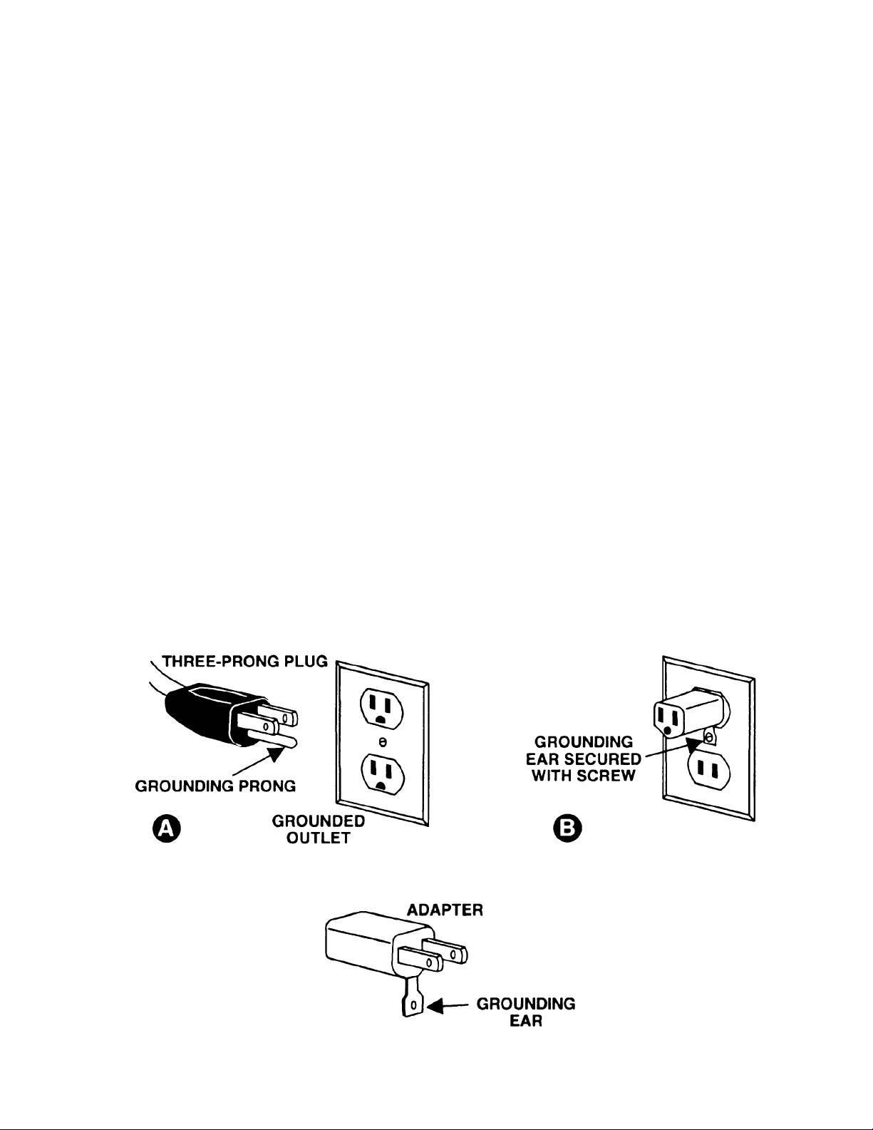
115 Volt Operation
As received from the f actory, your sander is ready to run at 115 volt oper ation. This sander, when wired
for 115 volt , is intended for use on a circuit that has an outlet and a plug that looks like the one illustrated
in (A). A temporary adapter, which look s l ike the adapter as illustrated in (B), may be used to connect
this plug to a two-pole receptacle, as shown in (B) if a properly grounded outlet i s not available. T he
temporary adapter should only be used until a properly grounded outlet can be installed by a qualified
electrician. This adapter is not applicable in Canada. The green colored ri gid ear, lug, or tab,
extendi ng from the adapter, must be connected to a permanent ground such as a properly gr ounded
outlet box, as shown in (B).
5
Page 6
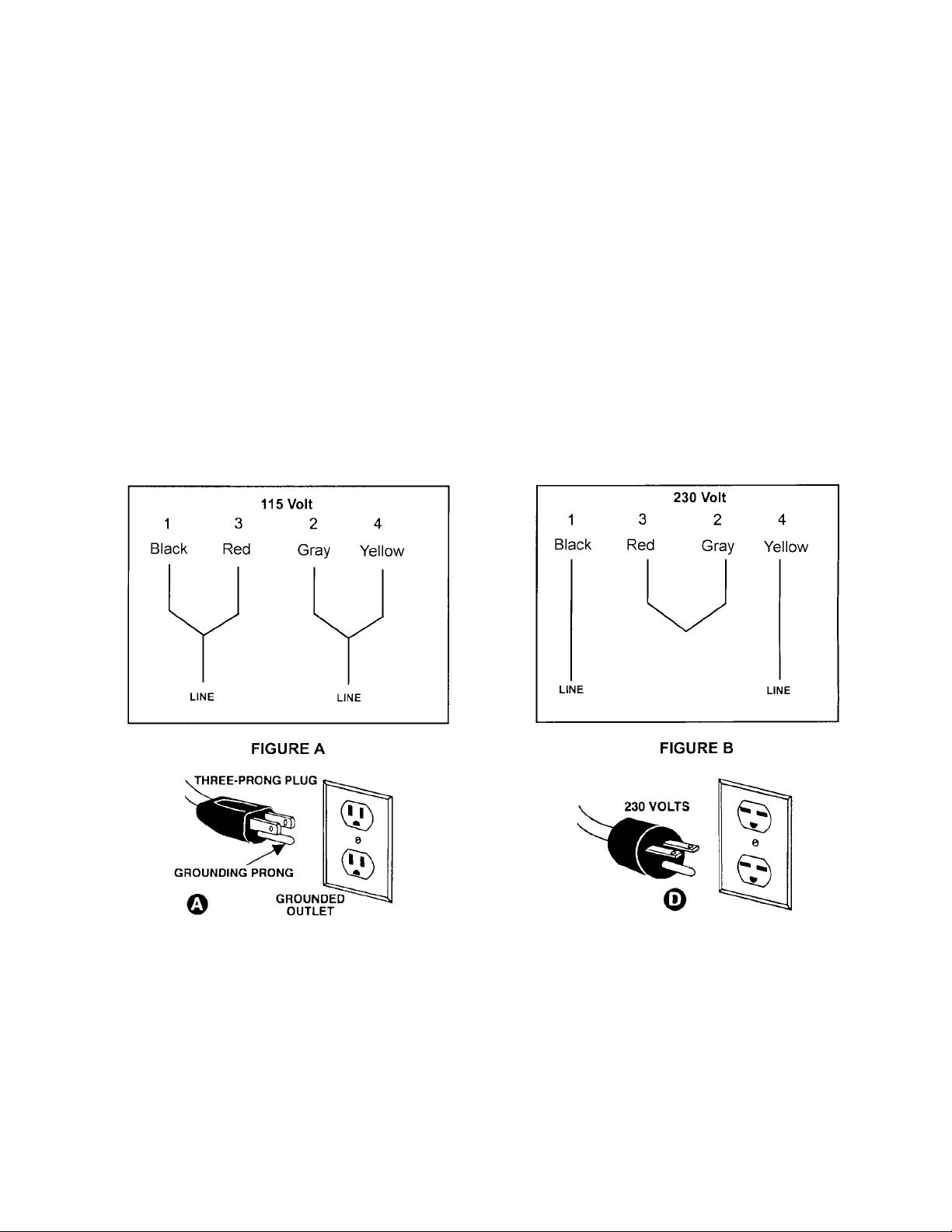
230 Volt Operation
If 230V, single phase operati on is desired, the following instructions must be fol lowed:
1. Disconnect the machine f rom the power source.
2. This POWERMATIC sander is supplied with four motor leads that are c onnec ted for 115V operation,
as shown in Figure A. Reconnect these four motor leads for 230V operati on, as shown in Figure B.
3. The 115V attachment plug (A) , supplied with t he sander, must be replaced with a UL/CSA listed plug
suitable for 230V operation (D). Contact your local A uthorized PO WERMA TIC Service Center or
qualified elec trici an for proper procedures to install the plug. The sander must comply with all local
and national c odes after the 230 volt plug is installed.
4. The sander with a 230 v olt plug should only be connected to an outlet having the same configuration
(D). No adapter is avai lable or should be used with t he 230 vol t plug.
Important: In all c ases (115 or 230 volt s), make certain the receptac le in question is properly grounded.
If you ar e not sure, hav e a r egistered elect r ician check the receptacl e.
6
Page 7

Specifications PDS-12CS
Stock Number............................................................................................................................1791201K
Disc Diameter.......................................................................................................................................12”
Table Tilt......................................................................................................................15° Up - 45° Down
Dust Chute Diameter..............................................................................................................................4”
Disc Tabl e ................................................................................................................. 16-3/8" W x 9-3/4” D
Motor........................................................................................................1-1/2 HP, 115/230V, 60Hz, 1Ph
Impeller................................................................................................................................................ 10”
Overall Dimensions.....................................................................................27-3/4” W x 25" D x 42-5/8” H
Net Weight (approx.) ....................................................................................................................189 Lbs.
Table of Contents
Warranty .................................................................................................................................................2
Warnings ....................................................................................................................... .......................3-4
Grounding Instructions.............................................................................................................................5
115V Operati on .......................................................................................................................................5
230V Operati on .......................................................................................................................................6
Specifications..........................................................................................................................................7
Table of Contents....................................................................................................................................7
Contents of the Shipping Carton..............................................................................................................8
Tools Required for Assembly & Adjustment .............................................................................................8
Unpacking ...............................................................................................................................................8
Stand Assembly.......................................................................................................................................9
Sander Assembly.....................................................................................................................................9
Collector Bag Assembly......................................................................................................... ................10
Table Adjustment...................................................................................................................................10
Sanding Disc Replacement....................................................................................................................11
Center Point ..........................................................................................................................................11
Brake.....................................................................................................................................................11
On/Off Switch........................................................................................................................................11
Lubrication.............................................................................................................................................11
Motor.....................................................................................................................................................11
Emptying Collector Bag.........................................................................................................................12
Optional Accessories.............................................................................................................................12
Troubleshooting.....................................................................................................................................12
Parts Breakdowns & Parts List..........................................................................................................13-17
Wiring Diagram .....................................................................................................................................18
The specif icat ions in thi s manual are giv en as general inf ormat ion and are not bindi ng. T he W MH Tool
Group reserves the right to ef fect, at any tim e and without prior notice, changes or alt erations to parts,
fittings, and accessory equi pment deem ed nec essary for any reason whatsoever.
7
Page 8

Contents of the Shipping Carton
PDS-12CS 12” Disc Sander
1. Sander
1. Sanding Disc
1. Table
1. Miter Gauge
1. Miter Gauge Fence
1. Owner's Manual
1. Warranty Card
Hardware Kit
4. Hex Head Bolt M 10x35
4. Flat Washer M10
4. Lock Washers M10
2. Hex Nut M6
4. Pan Head Flange Screw M6x12
1. Center Point
1. Right Angle Hex Wrench 3mm
1. Filler Bar
1. Socket Head Cap Screw M5x 8
Closed Stand
1. Stand
1. Inlet
2. Hangers
1. Ring Clamp
1. Collector Bag
Tools Required for Assembly &
Adjustments
1. 13mm Wrench or socket
1. Combination Square
WARNING
Read and understand the entire contents of
this manu al before attempting assembly or
operation of the disc sander!
Failure t o comply may cau se serious injury!
Unpacking
1. Remove all contents from the shipping
carton(s).
2. Report any damage to your distributor.
3. Do not discard any shipping material until
the sander has been assembled and is
running properly.
8
Page 9

Stand Assembly
1. With the help of another person lift the
sander (A, Fig. 1) onto the stand (B , Fi g. 1).
Feed the belt (C, Fi g. 1) t hrough the cut out
in the top of the stand.
2. Match t he hole pattern i n the stand with the
hole pattern in the sander.
3. Bolt the sander to the stand with four
M10x35 socket head c ap screw (D, Fig. 1),
four M10 lock washers (E, Fig. 1) and four
M10 flat washers (F, Fig. 1). Tighten the
nuts to secure the sander to the stand.
Sander Assembly
1. Unscrew the knob (G, Fig. 2), remove the
washer (H, Fig. 2) and the trunnion holder (I,
Fig. 2). Repeat for opposi te side.
2. Li ft the tabl e (J, F ig. 2) i nto posit ion and set
on top of t he spl it pins and threaded shaft.
3. Reinstall the trunnion holder, washer and
knob. Repeat for opposite side.
4. Make sure the trunni on and trunnion holder
engage and tighten t he k nobs.
5. Open t he door in t he cabinet to gai n access
to the belt. Make sure t he belt (K , Fi g. 3) is
seated in the sanding disc pulley.
6. Loosen two bolts (L, Fig. 3) to move the
tension roller (M, Fig. 3) out of the way.
Place the bel t on the fan pul ley (N, F ig. 3)
and rotate until t he belt seats in the pulley .
Tighten the tension rol ler agai nst the bel t as
shown in Figure 3. The tension roller is
adjusted properl y when it takes the slack out
of the belt.
WARNING
Avoid kickback by sanding in accord ance
with directional arrow. Sand on downward
side of disc. Sanding on the upward side
could cause the workpiece to fl y up causing
injury! Failure to comply may cause serious
injury!
9
Page 10

Collector Bag Assembly
1. Mount the inl et port (A, Fig. 4) to the cabinet
with four M6x12 pan head screws (B, F ig. 4).
2. Thread two M6 nuts (C, Fig. 4) on the shaft
of hanger rods (D, Fig. 4). Thread r ods into t he
cabinet and tighten nuts against t he c abinet.
3. Place the loops (E, Fig. 4) of the collector
bag onto the hanger rods.
4. Loosen ring clamp (F, Fig. 4) all the way
and place on the inlet port. Fit collector bag
opening onto inl et port, and secure i n place by
tightening the ring clamp.
Table Adjustment
The table stops have been set-up at t he factory .
However, if you run into a problem, or want to
check the table fol low the below listed steps.
1. Loosen knobs (G, Fig. 5) and move table
into the 90-degr ee position. Tighten k nobs
and place a square (H, Fig. 5) against the
table and sander disc. The square should
rest fl at against the table and the disc.
2. If adjustment is needed move the table so
that it rests 90 degrees from the table, and
loosen the hex nut (I , F ig. 5) and ti ghten t he
set screw (J, Fig. 5) until it contacts the
table surface. Tighten hex nut. This will
properly adjust the 90-degree stop.
3. Loosen knobs (G Fig. 5) and tilt table up
enough to pivot the stop (K, Fig. 5) out of
the way.
4. Tilt the t abl e down until it hit s t he 45- degree
stop (L, Fig. 5). Ti ghten t he l ock knobs, and
check the table with a combination square.
5. If adjustments needed, loosen hex nut (M,
Fig. 5) and adjust socket head screw (L, Fig.
5) until it contacts table. Tighten hex nut .
6. Always maintain a gap of approximately
1/16” between the table edge, and disc. If
adjustment is necessary loosen hex cap
bolts (N, Fig. 6) and move the table into
position. Tighten hex cap bolts.
7. The table can be til t ed between 15° up - 45°
down by loosening lock k nobs and ti l ti ng the
table to t he desired angle. Tighten knobs.
8. If you want to tilt the table up you need to
pivot the stop (E, Fig. 5) out of the way.
10
Page 11

Sanding Disc Replacement
1. Disconnect machine from the power
source.
2. Remove t he knobs (A, Fig. 7), washers (B,
Fig. 7), and trunnion holders (C, Fig. 7)
followed by the table assembly (D, Fig. 7).
3. Remove old sanding disc by striping from
wheel. Use a cleaner and putty knife to
remove the residue. Make sure the disc
plate is clean and dry.
4. Press the new disc firmly i nto place.
Center Point
The center point (E, Fig. 8) provided with sander
can be used for sanding circles. Slide the
center point into the miter slot that is
perpendicular to the sanding disc. The radi us of
the desired circle should be the distance from
the center point to the sanding disc. Lock the
center point in position by tightening the set
screws. Cut the wood to the approximate
diameter and press on to the center point.
Rotate the wood until the desired results are
achieved.
Filler Bar
The f iller bar (J, Fig. 8) should be added when
sanding small workpieces. Secur e in pl ace with
the socket head cap screw (K, Fig. 8). W hen
not using the filler bar thread the socket head
cap screw (K, Fig. 8) in the tapped hole as a
stop.
Brake
After turning the sander “OFF” you can press
the brake (F, Fi g. 8) to sl ow, or stop the sanding
disc.
On/Off Switch
The machine can be turned “ON” or “OFF” by
pushing the appropri ate button (G, Fig. 8).
Lubrication
Lubricate the trunnion, and trunnion holder (H,
Fig. 8) if t he table does not ti lt smoothly.
Motor
Make frequent i nspecti ons of the m ot or f an c over,
and blow out (with low pressure air hose) or
vacuum any accumulation of foreign material in
order to maintain normal motor ventil ation.
WARNING
All electrical connections must be done by
a qualif ied electrician. All adjustments or
repairs must be done with the sander
disconnected from the power so urce,
unplugged. Failure to comply may result in
serious injury!
The PDS-12CS di sc sander i s rat ed 115V/230V ,
Prewired 115V.
If you want t o run the PDS-12CS on 230V refer
to the wiri ng diagram found on the i nside of the
switch box cover (I, Fig. 8).
Before hooking up to the power source, make
sure that the switch is in the off position.
11
Page 12

Emptying the Collector Bag
CAUTION
Wearing a part icle mask/respirat or for
protection against fine dust particles during
cleaning is highly recommended.
During f irst use and af ter cl eaning, t he bag m ay
allow some dust to escape. This is normal and
will stop after a short period of time.
Clean the collector bag frequently to keep the
collector's performance at its optimum. To
clean:
1. Disconnect the machine from the power
source, unplug.
2. Remove the collector bag from the hanger
rods.
3. Loosen the ring clamp and remove the bag.
4. Empty the contents into an appropriate
container. The bag is easily emptied by
unzipping t he bottom of the bag.
Troubleshooting
Optional Accessories
57620025: JET St ik Abrasive Belt and Disc
Cleaner.
JDS-12B Sandi ng Disc PSA Alum inum Oxide
“J” Weight Cloth Back.
12” 36 Grit 50 Grit 60 Grit
Stock
Number
Master
Carton
12” 80 Grit 100 Grit 120 Grit
Stock
Number
Master
Carton
57698525 57698650 57698750
25 50 50
57698850 57698950 57699050
50 50 50
Trouble Possible Cause Solution
Sander will not start
Sanding disc does not come
up to speed
Machine vi brates excessively
Sanded edge not square
Sanding marks on wood
1. Sander unplugged fr om wall
or motor
2. Fuse blown or circui t breaker
tripped
3. Cord damaged
1. Extension cor d too light or
too long
2. Low current
1. Stand or base on uneven
surface
1. Table not square to sanding
disc
1. Work held still
2. Wrong grit sanding disc
3. Feed pressure too great
4. Sanding against the gr ain
1. Check all plug connections
2. Replace fuse or reset c ircuit
breaker
3. Replace cord
1. Replace with adequate siz e
and length cord
2. Contact a quali fied
electrician
1. Adjust stand or base so that
it rests evenly on the floor
2. Bolt down
1. Use a square to adjust table
to sanding disc
1. Keep workpiece moving
2. Use coarser grit f or stoc k
removal and fine grit for
finish sanding.
3. Never force workpiece
4. Sand with the grain
12
Page 13

Base Assembly Breakdown
13
Page 14

Parts List for the PDS-12CS
Base Assembly
Index Part
No. No. Description Size Qty
1..........612083.........................Closed Stand......................................... ...............................................1
2..........612097.........................Door w/Latch Assembly......................... ...............................................1
3..........150503.........................Latch Assembly ..................................... ...............................................1
4..........150503-1...................... Spacer................................................... ...............................................2
5.......... SP040100 .................... Pan Head Bolt .......................................M4 x 5.....................................2
6..........331003.........................Impeller.................................................10”..........................................1
7..........410030.........................Gasket................................................... ...............................................1
8.......... SH080402....................Hex Head Bolt .......................................M8 x 20 (LH)...........................1
9.......... TS-1551061 .................Lock Washer.........................................M8 ..........................................1
10........TS-1550061................. Fl at Washer........................................... M8 x 30...................................1
11........612088......................... Cover .................................................... ...............................................1
12........SG069300.................... Hex Flange Bolt.....................................M6 x 12...................................8
13........612089......................... Bearing Housing.................................... ...............................................1
14........TS-1551041................. Lock Washer.........................................M6 ..........................................3
15........TS-1482031................. Cap Screw.............................................M6 x 16...................................3
16........612112......................... Bushing................................................. ...............................................1
17........BB-6204LLU ................Ball Bearing...........................................6204LLU .................................2
18........RR470000.................... Retaining Ring.......................................R47.........................................1
19........612090......................... Shaft...................................................... ...............................................1
20........612091......................... Pulley.................................................... ...............................................1
21........TS1523031 ..................Set Screw..............................................M6 x 8.....................................2
22........KD050530.................... Key........................................................5 x 5 x 30................................2
23........612121......................... Bushing................................................. ...............................................1
24........612094......................... Idle W heel Bracket ................................ ...............................................1
25........TS1550071 ..................Flat Washer...........................................M10 x 20.................................2
26........BB-6200ZZ .................. Ball Bearing...........................................6200ZZ ...................................2
27........TS-149105...................Hex Head Bolt .......................................M10 x 35.................................1
28........TS-1540072................. Nut ........................................................M10.........................................1
29........TS-1550041................. Fl at Washer........................................... M6 x 13...................................2
30........TS-1551041................. Lock Washer.........................................M6 ..........................................2
31........TS-1482031................. Cap Screw.............................................M6 x 16...................................2
32........412007......................... Inlet Port................................................4”............................................1
33........SF069300.................... Pan Head Flange Bolt............................M6 x 12...................................4
34........423968......................... Ring Clamp ...........................................4” ............................................1
35........612095......................... Hanger .................................................. ...............................................2
36........TS-1540041................. Hex Nut.................................................M6 ..........................................2
37........612085......................... Collector Bag......................................... ...............................................1
38........150527......................... Sponge.................................................. ...............................................2
39........620015......................... Washer..................................................M10 x 20.................................1
40........TS-1551071................. Lock Washer.........................................M10.........................................1
14
Page 15

Sander Assembly Breakdown
15
Page 16

Parts List for PDS-12CS
Sander Assembly
Index Part
No. No. Description Size Qty
1..........612111.........................Base...................................................... ...............................................1
2.......... TS-1505051 .................Socket Head Cap Screw........................M10 x 35.................................4
3.......... TS-1551071 .................Lock Washer.........................................M10.........................................4
4.......... TS-1550071 .................Flat W asher...........................................M10 x 20.................................4
5.......... MA612002.................... Motor.....................................................1-1/2HP, 1 Ph, 60HZ...............1
............ PDS12CS-MFC............Motor Fan Cover (not shown) ................ ...............................................1
............ PDS12CS-MF..............Motor Fan (not shown)........................... ...............................................1
............ PDS12CS-CS.............. Centrifugal Switch (not shown)............... ...............................................1
............ PDS12CS-CC..............Capacit or Cover (not shown) ................. ...............................................1
............ PDS12CS-JBC.............Junction Box Cover (not shown)............ ...............................................1
............ PDS12CS-SC.............. Starting Capac itor (not shown)...............200MFD, 125V A C.....................
............ PDS12CS-RC..............Running Capacitor (not shown)..............40uF , 250V ...............................
6..........411051.........................Switch Box ............................................ ...............................................1
7..........411053.........................Switch Plate........................................... ...............................................1
8.......... ST039304 .................... Tapping Screw.......................................M3.5x12 (AB)..........................6
9.......... SP059400 .................... Pan Head Screw....................................M5 x 16...................................1
10........WE050000...................Star Washer..........................................M5 ..........................................1
11........NF050800....................Hex Flange Nut .....................................M5 ..........................................2
12........994505......................... Switch.................................................... ...............................................1
13........SP059300....................Pan Head Screw....................................M5 x 12...................................2
14........998621......................... Strain Relief........................................... ...............................................1
15........IC314101..................... Power Cord............................................ ...............................................1
16........TS-1490041................. Cap Screw.............................................M8 x 25...................................4
17........TS-1551061................. Lock Washer.........................................M8 ..........................................4
18........TS-1550061................. Fl at Washer........................................... M8 x 12...................................4
19........KD050535.................... Key........................................................5 x 5 x 35................................1
20........612114......................... Disc Guard............................................ ...............................................1
21........SJ080400..................... Pan Head Bolt.......................................M8 x 20...................................4
22........612104......................... Pulley.................................................... ...............................................1
23........VB-A39........................V-Belt....................................................A39.........................................1
24........TS-1523031................. Set Screw.............................................. M6 x 8.....................................1
25........612120......................... Sanding Disc ......................................... ...............................................1
26........612113......................... Washer.................................................. ...............................................1
27........SM089400....................Countersunk Head Bol t..........................M8 x 16...................................1
28........57698525..................... 12” Disc Sandi ng P aper 36 Grit ............. .............................................25
............ 57698650..................... 12” Disc Sanding Paper 50 Grit ............. .............................................50
............ 57698750..................... 12” Disc Sanding Paper 60 Grit ............. .............................................50
............ 57698850..................... 12” Disc Sanding Paper 80 Grit ............. .............................................50
............ 57698950..................... 12” Disc Sanding Paper 100 Grit............ .............................................50
............ 57699050..................... 12” Disc Sanding Paper 120 Grit............ .............................................50
29........612118......................... Brake Base............................................ ...............................................1
30........SP040200....................Pan Head Bolt .......................................M4 x 10...................................3
31........612116......................... Brake..................................................... ...............................................1
32........PS042600....................Spring Pin..............................................4 x 26......................................1
33........612115......................... Stop Handle........................................... ...............................................1
34........612140......................... Spring.................................................... ...............................................1
35........TS-1550031................. Fl at Washer........................................... M5 x 12...................................1
36........612084......................... Front Cover........................................... ...............................................1
37........SF069200.................... Pan Head Flange Bolt............................M6 x 8.....................................2
38........150031......................... Pin......................................................... ...............................................3
39........612035......................... Stop Bracket.......................................... ...............................................1
40........TS-1550061................. Fl at Washer........................................... M8 x 18...................................1
16
Page 17

Index Part
No. No. Description Size Qty
41........TS-1551061................. Lock Washer.........................................M8 ..........................................1
42........TS-1490041................. Cap Screw.............................................M8 x 25...................................1
43........612010......................... Locating Block....................................... ...............................................1
44........TS-1540041................. Nut ........................................................M6 ..........................................1
45........TS-1523071................. Set Screw.............................................. M6 x 25...................................1
46........PS052500....................Spring Pin..............................................5 x 25 ......................................1
47........612135-1..................... Table..................................................... ...............................................1
48........612046......................... Trunnion................................................ ...............................................2
49........TS-1551061................. Lock Washer.........................................M8 ..........................................4
50........TS-1490021................. Cap Screw.............................................M8 x 16...................................4
51........612054......................... Table Bracket........................................ ...............................................1
52........PS063000....................Spring Pin..............................................6 x 30 ......................................4
53........612038......................... Trunnion Holder (A) ............................... ...............................................1
54........612098......................... Knob......................................................M8 ..........................................2
55........SH081100.................... Hex Head Bolt.......................................M8 x 55...................................2
56........TS-1540061................. Nut ........................................................M8 ..........................................1
57........TS-1504041................. Socket Head Cap Screw........................M8 x 20...................................1
58........TS-1550061................. Fl at Washer........................................... M8 x 18...................................2
59........612052......................... Trunnion Holder (B) ............................... ...............................................1
60........612037......................... Table Bracket........................................ ...............................................1
61........TS-1490021................. Cap Screw.............................................M8 x 16...................................4
62........TS-1551061................. Spring Washer.......................................M8 ..........................................4
63........TS-1550061................. Fl at Washer........................................... 8 x 18......................................4
64........150031......................... Pin......................................................... ...............................................2
65........AB612143....................Circle Gauge Assembly ......................... ...............................................1
66........AB612148....................Miter Gauge Assembly .......................... ...............................................1
67........TS-1551061................. Lock Washer.........................................M8 ..........................................4
68........TS-1551021................. Lock Washer.........................................M4 ..........................................2
69........TS-1503041................. Socket Head Cap Screw........................M6 x 16...................................1
70........TS-1540041................. Hex Nut.................................................M6 ..........................................1
71........L200000....................... Elastic ................................................... ...............................................1
72........612171......................... Filler Bar................................................ ...............................................1
73........TS-1502011................. Socket Head Cap Screw........................M5x8.......................................1
* ..........PDS12CS-HK.............. Hardware Kit (not shown)....................... .................................................
............ PDS12CS-WL.............. Warning Label (not shown).................... .................................................
............ PDS12CS-ID................ I.D. Label (not shown)............................ .................................................
............ PDS12CS-JL................Powermatic Label (not shown)............... .................................................
17
Page 18

Wiring Diagram
18
 Loading...