

Page 1
This .pdf document is bookmarked
Operating Instructions and Parts Manual
18-Inch, 20-Inch Band Saw
Models: JWBS-18QT, -18QT-3, -20QT-3, -20QT-5
JWBS-18QT JWBS-20QT
JET
427 New Sanford Road
LaVergne, TN 37086-4184, USA Part No. M-710750B
Ph.: 800-274-6848 Revision C2 04/2014
www.jettools.com Copyright © 2014 JET
Page 2

Warranty and Service
JET warrants every product it sells against manufacturers’ defects. If one of our tools needs service or repair, please
contact Technical Service by calling 1-800-274-6846, 8AM to 5PM CST, Monday through Friday.
Warranty Period
The general warranty lasts for the time period specified in the literature included with your product or on the official
JET branded website.
• JET products carry a limited warranty which varies in duration based upon the product. (See chart below)
• Accessories carry a limited warranty of one year from the date of receipt.
• Consumable items are defined as expendable parts or accessories expected to become inoperable within a
reasonable amount of use and are covered by a 90 day limited warranty against manufacturer’s defects.
Who is Covered
This warranty covers only the initial purchaser of the product from the date of delivery.
What is Co vered
This warranty covers any defects in workmanship or materials subject to the limitations stated below. This warranty
does not cover failures due directly or indirectly to misuse, abuse, negligence or accidents, normal wear-and-tear,
improper repair, alterations or lack of maintenance.
Warranty Limitations
Woodworking products with a Five Year Warranty that are used for commercial or industrial purposes default to a
Two Year Warranty. Please contact Technical Service at 1-800-274-6846 for further clarification.
How to Get Technical Support
Please contact Technical Service by calling 1-800-274-6846. Please note that you will be asked to provi d e pr o of
of initia l p u rch a s e whe n calling. If a product requires further inspection, the Technical Service representative will
explain and assist with any additional action needed. JET has Authorized Service Centers located throughout the
United States. For the name of an Authorized Service Center in your area call 1-800-274-6846 or use the Service
Center Locator on the JET website.
More Information
JET is constantly adding new products. For complete, up-to-date product information, check with your local distributor
or visit the JET website.
How S tate Law A pplies
This warranty gives you specific legal rights, subject to applicable state law.
Limitations on This Warranty
JET LIMITS ALL IMPLIED WARRANTIES TO THE PERIOD OF THE LIMITED WARRANTY FOR EACH PRODUCT.
EXCEPT AS STATED HEREIN, ANY IMPLIED WARRANTI ES OF MERCHANTABILITY AND FITNESS FOR A
PARTICULAR PURPOSE ARE EXCLUDED. SOME STATES DO NOT ALLOW LIMITATIONS ON HOW LONG AN
IMPLIED WARRANTY LASTS, SO THE ABOVE LIMITATION MAY NOT APPLY TO YOU.
JET SHALL IN NO EVENT BE LIABLE FOR DEATH, INJURIES TO PERSONS OR PROPERTY, OR FOR
INCIDENTAL, CONTINGENT, SPECIAL, OR CONSEQUENTIAL DAMAGES ARISING FROM THE USE OF OUR
PRODUCTS. SOME STATES DO NOT ALLOW THE EXCLUSION OR LIMITATION OF INCIDENTAL OR
CONSEQUENTIAL DAMAGES, SO THE ABOVE LIMITATION OR EXCLUSION MAY NOT APPLY TO YOU.
JET sells through distributors only. The specifications listed in JET printed materials and on official JET website are
given as general information and are not binding. JET reserves the right to effect at any time, without prior notice,
those alterations to parts, fittings, and accessory equipment which they may deem necessary for any reason
whatsoever. JET
Product Listing with Warranty Period
90 Days – Parts; Consumable items; Light-Duty Air Tools
1 Year – Motors; Machine Accessories; Heavy-Duty Air Tools; Pro-Duty Air Tools
2 Year – Metalworking Machinery; Electric Hoists, Electric Hoist Accessories; Woodworking Machinery used
for industrial or commercial purposes
5 Year – Woodworking Machinery
Limited Lifetime – JET Parallel clamps; VOLT Series Electric Hoists; Manual Hoists; Manual Hoist
Accessories; Shop Tools; Warehouse & Dock products; Hand Tools
NOTE: JET is a division of JPW Industries, Inc. References in this document to JET also apply to JPW Industries,
Inc., or any of its successors in interest to the JET brand.
®
branded products are not sold in Canada by JPW Industries, Inc.
2
Page 3

Table of Contents
Warranty and Servic e .............................................................................................................................. 2
Table of Contents .................................................................................................................................... 3
Warning ................................................................................................................................................... 4
Introduction ............................................................................................................................................. 6
Specifica tions ................................................................................................................ .......................... 6
Grounding Inst r uc tions ............................................................................................................................. 7
Model JWBS-18QT .............................................................................................................................. 7
Models JWBS-18-3, - 20QT - 3, - 20QT - 5 ................................................................................................ 8
Unpac king ............................................................................................................................................... 9
Contents of Shipping Container ............................................................................................................ 9
Assembly .............................................................................................................................................. 10
Handwheel ......................................................................................................................................... 10
Mounting the Table ............................................................................................................................ 10
Rail Assembly .................................................................................................................................... 11
Fence Assembly and Adj ustm ent ....................................................................................................... 11
Resaw Guide ..................................................................................................................................... 13
Miter Gauge ....................................................................................................................................... 13
Adjustments .......................................................................................................................................... 14
Adjusting 90 Degree Table Stop ......................................................................................................... 14
Installing/Changing Blades ................................................................................................................. 15
Blade Tension .................................................................................................................................... 16
Blade Tracking ................................................................................................................................... 16
Overview – Bearing Adjustments ........................................................................................................ 17
Upper Bearing Adjustments ................................................................................................................ 17
Lower Bearing Adjustments ................................................................................................................ 18
Blade Lead ........................................................................................................................................ 19
Changing the Blade Speed................................................................................................................. 20
Belt Tension ....................................................................................................................................... 2 0
Replacing the Poly V-Belt ................................................................................................................... 2 1
Pulley Alignment ................................................................................................................................ 22
Operating Controls ................................................................................................................................ 23
Start/Stop Switch ............................................................................................................................... 23
Brake Pedal (JW BS-20QT only ) ......................................................................................................... 23
Operation .............................................................................................................................................. 2 4
General Procedure ............................................................................................................................. 24
Ripping .............................................................................................................................................. 24
Crosscutting ....................................................................................................................................... 24
Resawing ........................................................................................................................................... 25
Saw Blade Selection .......................................................................................................................... 25
Blade Breakage ................................................................................................................................. 26
Maintenance .......................................................................................................................................... 26
Blade Selecti on Guide ........................................................................................................................... 27
Parts ..................................................................................................................................................... 29
Electri c al Connec tions ........................................................................................................................... 48
3
Page 4

Warning
1. Read and understand the ent ire owner's manual bef or e att em pting assembly or operation.
2. Read and understand the warnings po sted on the m achine and i n thi s manual. Fail ure to comply wit h
all of these warnings m ay cause seriou s i njury.
3. Replace the warning labels if they become obscured or removed.
4. This band saw is designed and i ntended for use by proper ly trained and experienced per sonnel onl y.
If you are not familiar with the proper and safe operation of a band saw, do not use until proper
training and knowledge have been obtained.
5. Do not use this band saw for other than its intended use. If used for other purposes, JET discl aims
any real or implied warrant y and holds itself harmless from any injury that may result from that use.
6. Always wear approv ed safety glasses/face shields whil e using this band saw. Everyday eyeglasses
only have impact resi stant lenses; they are not safety glasses.
7. Before operating this band saw, remove tie, rings, watches and other j ewelry, and roll sleeves up past
the elbows. Remove all loose cl othing and c onfine long hair. Non- sli p footwear or anti- skid floor stri ps
are recommended. Do not wear gloves.
8. Wear ear protector s (plugs or muffs) during ext ended peri ods of oper ation.
9. Some dust created by power sanding, sawing, grinding, drilling and other construction activities
contain chemi cals known to cause cancer , bir th defects or other r eproductiv e harm . Some exampl es
of these chemic als are:
• Lead from lead based paint.
• Crystalli ne sil ic a from bricks, cement and other m asonry pr oduc ts.
• Arsenic and chromium from chemically treated lumber .
Your risk of exposure varies, depending on how often you do this type of work. To reduce your
exposure to these chemicals, work in a well-ventilated area and work with approved safety
equipment, such as face or dust masks that are specifically designed to filter out microscopic
particles.
10. Do not operate this machi ne while tired or under the influence of drugs, alcohol or any medication.
11. M ak e c er tain the switch is in the OFF position before connecting the m achine to the power supply.
12. M ak e c er tain the machine is properl y grounded.
13. M ak e all machine adjustments or maintenance with the machine unplugged from the power source.
14. Remove adjusting keys and wrenches. Form a habit of checking to see that keys and adjusting
wrenches are removed from the machine before turning it on.
15. Keep safety guards in place at all times when the machi ne is in use. If removed for maintenance
purposes, use extreme caution and replace the guards immediately.
16. Check damaged parts. Before further use of the machine, a guard or other part that is damaged
should be carefully checked to determine that it will operate properly and perform its intended
function. Chec k for alignment of moving par ts, binding of moving parts, breakage of parts, mounting
and any other conditions that may affect its operation. A guard or other part that is damaged should
be properly repaired or replaced.
17. P r ov ide for adequate space surroundi ng work ar ea and non-glare, ov er head lighting.
18. K eep the floor around the machi ne cl ean and fr ee of scrap material, oil and grease.
19. K eep v isitors a safe distance fr om the work area. Keep ch ildren away.
4
Page 5

20. M ak e y our workshop child proof wit h padloc k s, m aster swit c hes or by r em ov ing starter keys.
21. Giv e your work undivi ded attention. Looki ng around, carryi ng on a conversati on and “horse-play” ar e
careless acts that can r esul t in serious injury.
22. Maintain a balanced stance at all times so that you do not fall or lean against the blade or other
moving part s. Do not over r eac h or use excessive force to perform any mac hine operation.
23. Use the ri ght t ool at the cor rect speed and feed r ate. Do not for ce a tool or attachment to do a job for
which it was not designed. T he ri ght tool will do the job better and safer.
24. Use recom mended accessories; i mproper accessories m ay be hazardous.
25. Mai ntain tools with care. Keep bl ades sharp and clean for the best and saf est performance. Follow
instructions for lubricating and changing accessories.
26. Turn off the machine bef ore cleaning. Use a brush or compressed air t o remove chips or debris — do
not use your hands.
27. Do not stand on the machine. Seri ous i njury could occur if the machine tips over.
28. Never leave the mac hine r unning unattended. Turn the power off and do not leav e the m ac hine until it
comes to a complete stop.
29. Remove loose items and unnecessary work pieces from the area before starting the machine.
Familiariz e you rself with the following safety no tices used in this manual:
This means th at if precaut ions are n o t heeded, it may resul t i n minor i njury and /or
possible machine damage.
This means that if p recautions are not heeded, it may result in serious injury or
possibly even d eath.
- - SAVE THESE INSTRUCTIONS - -
5
Page 6

Introduction
This manual is provi ded by JET coveri ng the safe operation and m aintenance procedur es for JET model
JWBS-18QT and JWB S-20QT seri es band sa ws. This m anual contai ns instr uctions on i nstal lati on, saf ety
precautions, gener al oper ati ng procedur es, mai ntenance i nstructi ons and parts breakdo wn. Thi s mac hine
has been designed and con structed t o provide year s of troubl e free operation if used in accordanc e with
instructi ons set forth in this manual. If there are any questions or comm ents, please contact either your
local suppli er or JET. JET can also be reached at our web site: www.jettools.com.
Specifications
Model Number .................................. JWBS-18QT............. JWBS-18QT-3 ........ JWBS-20QT-3 ........JWB S-20QT-5
Stock Number ......................................... 710750B...................... 710751B .................. 708754B ................. 708755B
Band Saw Nominal Size (in.) ............................. 18................................18 ............................ 20 ........................... 20
Capacities and Speeds:
Cutting Capacity (height) (in.) ............................ 12................................12 ...................... 12-1/4 ..................... 12-1/4
Cutting Capacity (width) (in.) ....................... 18-3/8.......................... 18-3/8 ............................ 20 ........................... 20
Maximum Rip Left of Blade w/Fence (in.) ..... 16-1/2.......................... 16-1/2 ...................... 18-1/2 ..................... 18 - 1/2
Maximum Rip Right of Blade w/Fence (in.) .... 7-5/8............................ 7-5/8 ........................ 9 -3/ 4 ....................... 9-3 /4
Blade Length (in.) ........................................... 137.............................. 137 .......................... 150 ......................... 150
Blade Speed (FPM) ............................. 1800/3200................... 1800/3200 ................ 1800/3200 ............... 1800/3200
Blade provided........................... hook, 3/4” x 4 TPI........ hook, 3/4” x 4 TPI ........ hook, 1” x 3 TPI ....... hook, 1” x 3 TPI
Minimum Blade Wid th (in.) ............................... 1/8............................... 1/8 ........................... 1 /8 .......................... 1/8
Maximum Blade Width (in.) ........................... 1-1/2............................ 1-1/2 ........................ 1 -1/ 2 ....................... 1-1/ 2
Wheel Diameter (in.) ................................... 18-5/8.......................... 18-5/8 ...................... 20-1/2 ..................... 20-1/2
Table and Fence:
Table Size (in.) ....................................... 19” x 19”...................... 19” x 19” ................. 21" x 21" ................. 21" x 21"
Table Tilt (degrees) ........................... 45°R to 10°L................ 45 °R to 1 0°L ............ 45°R to 10°L ............ 45°R to 10°L
Table Height from Floor (in.) ........................ 37-1/2.......................... 37-1/2 ...................... 36-1/8 ..................... 36-1/8
Fence Size (LxWxH/in.) ........... 23-5/8x1-3/4x3-1/2....... 23-5/8x1-3/4x3-1/2 ... 23-5/8x1-3/4x3-1/2 .. 23-5/8x1-3/4x3-1/2
Resaw post (LxDia./in.) ........................... 6 x 1-1/8...................... 6 x 1-1/8 .................. 6 x 1-1/8 .................. 6 x 1-1/8
Dust Collection:
Dust Port Outside Diam eter (in.) ......................... 4................................. 4 .............................. 4 ............................. 4
Minimum Extract ion Volume Requ ired (CFM) .. 400.............................. 400 .......................... 400 ......................... 400
Overal l Dimensions (HxWxD/in.) .. 73 x 41-1/2 x 30........... 73 x 41-1/2 x 32 ....... 74 x 41-1/2 x 37 ....... 74 x 41-1/2 x 39
Motor an d E le ctricals:
Motor.................................... 1.75HP(1.3kW), 1PH....... 3HP(2.2kW), 1PH ..... 3HP(2.2kW), 1PH .... 5HP(3.7kW), 1PH
115/230V
Start Capacitor........................... 300MFD 125VAC......... 300MFD 125VAC ..... 300MFD 125VAC .... 300MFD 250VAC
Run Capacitor ................................ 4 0μF 250VAC.............. 60μF 250VAC .......... 60μF 250VAC .......... 50μF 450VAC
Power transfer ..................................... poly-V belt................... poly-V belt ................ poly-V belt ............... poly-V belt
Power plug included........................................ yes................................no ............................ no ........................... no
Recommended circuit size
Weights:
Net Weight (lbs.) ............................................. 375............................ 381 ......................... 562 ........................... 595
Shipping Weight (lb s.) ..................................... 452 ........................... 459 ......................... 643 ........................... 676
1
Prew ired 115V
2
Subject to local and national electrical codes.
The above specifications were current at the time this manual w as published, but because of our policy of continuous
improvement, JET reserves the right to change specifications at any time and without prior notice, without incurring
obligations.
1
, 17.6/8.8A, 60Hz 230V, 13A, 60Hz 230V, 13A, 60Hz 230V, 21A, 60Hz
2
..................... 40A/20A ............................. 30A .......................... 30A ......................... 50A
6
Page 7
Grounding Instructions
This machine must be
grounde d while in use to protect the ope r a t or
from electri c sho ck.
In the event of a malfunction or breakdown,
grounding provi des a path of least resistance for
electric current to reduce the risk of electric
shock. This machi ne is equipped wit h an el ect ric
cord having an equipment-grounding conductor
and a grounding plug. The plug must be plugged
into a matching outlet that is properly installed
and grounded in accordanc e with all local codes
and ordinances.
Do not modify the pl ug pr ovided. If it will not fit
the outlet, have the proper outlet installed by a
qualified elec trician.
Improper connection of the equipmentgrounding conductor can result in a risk of
electric shock. The conductor, with insulation
having an outer surface that is green with or
without yellow stripes, is the equipmentgrounding conduct or. If repair or replacement of
the electric cord or plug is necessary, do not
connect the equipment -groundi ng conductor to a
live terminal.
Check with a qualified electrician or service
personnel if the grounding instructions are not
completely understood, or if in doubt as to
whether the tool is properl y grounded. Use only
three wire extension cords that have thr ee-prong
grounding plugs and t hree-pole recept acles that
accept the tool ’s pl ug.
Repair or replace a damaged or worn cord
immediately.
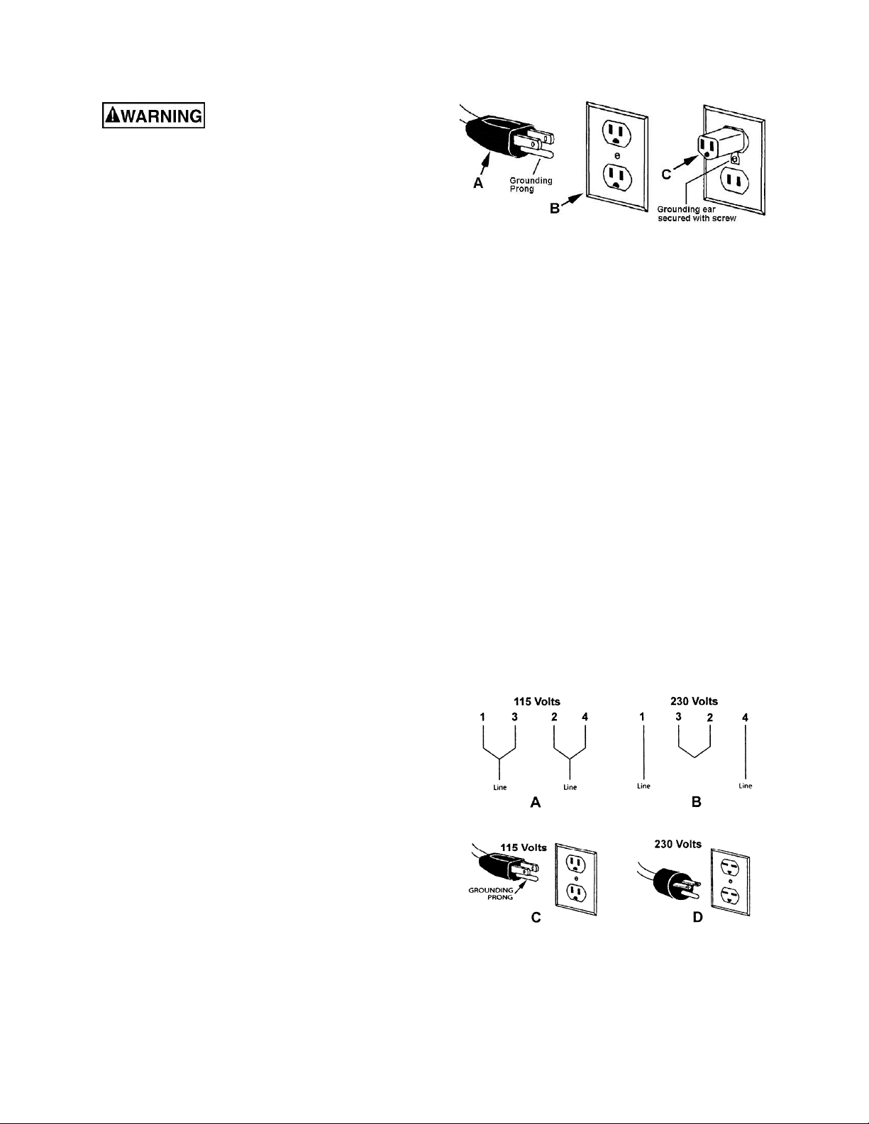
properly grounded outlet box, as shown in
C, Fig. 1.
Figure 1
230 Volt Operation
To convert the JWBS-18QT from 115V to 230V,
single phase operat ion, the following i s strongly
recommended:
Contact your local Authorized JET Service
Center or qualified electrician for proper
procedures to install the plug. The band saw
must comply with all local and national codes
after the 230V pl ug is i nstalled.
Change the lead wires at t he motor j unction box
as shown in B, Figure 2.
The 115V attachment plug supplied with the
band saw (C, Fig. 2) must be replaced with a
UL/CSA listed plug suitable for 230V operation
(D, Fig. 2).
The band saw with a 230V pl ug should only be
connected to an outlet having the same
configurati on (D, Fig. 2). No adapter is availabl e
or should be used with the 230V plug.
Important: In all cases (115 or 230 volts), make
certain the receptacle in question is properly
grounded. If you are not sure, have a regi stered
electrici an c hec k the rec eptacle.
Model JWBS-18QT
Model JWBS-18QT Band Saw has a 1-3/4 HP 1
phase motor and is wired from the factory for
115 volt operation, but can be rewired for 220
volts.
115 Volt Operation
The JWBS-18QT Band Saw comes equipped
wit h a plug that looks like A, Fig. 1. and is used
in an outlet th at loo k s l i k e B , F i g. 1. A temporary
adapter with a grounding ear secured with a
screw (C, Fig. 1) may be used to connect this
plug to a two-pole receptacle if a properly
grounded outlet i s not available. The tem porary
adapter should only be used until a properly
grounded outlet can be installed by a qualified
electrician. This adapter is not applicable in
Canada. T he green colored grounding ear, l ug,
or tab, extending from the adapter, must be
connected to a permanent ground such as a
Figure 2
7
Page 8

Models JWBS-18-3, -20QT-3, -20QT-5
Band saw models JW BS-18QT-3, JWBS-20QT3 and JWBS-20QT- 5 are wired from the factory
for 230 volt operation only. Refer to
Specifications for phase and HP ratings.
A plug is not inc luded. You may either install a
plug or “hard-wire” the band saw directly to a
control panel.
If connecti ng a plug, use a proper UL/CS A li sted
2-pole, 3-wire grounding plug suitable for 230V
operation.
If the band saw is to be hard-wired to a panel,
make sure a disconnect is available for the
operator. During hard-wiring of the band saw,
make sure the f uses have been removed or the
breakers have been tripped in the circuit to
which the band saw will be c onnected. Place a
warning placard on the fuse holder or circuit
breaker to prevent it being turned on while the
machine is being wired.
Circuit Information
The Band Saw should be connected to a
dedicated circuit with a circuit breaker or time
delay fuse with t he appropriat e amperage rati ng.
See Table 1 for recommended circuit sizes.
NOTE: These are recommendations only – all
local codes must be giv en pr ior ity.
Extension cords
The use of an extension cord is not
recommended f or this band saw. Try to positi on
your machine wit hin reach of the power suppl y.
If an extension cord bec omes necessary, mak e
sure the cord rating is suitabl e for the amperage
listed on the machine’s motor plate. An
undersized cord wil l cause a drop in line voltage
resulting in loss of power and overheating.
Use the chart in Table 2 as a general guide in
choosing the correct size cord. If in doubt, use
the next heav ier gauge. The smaller the gauge
number, the heavier the cord.
Recommended
Model Voltage
JWBS-18QT
710750B
JWBS-18QT-3
710751B
JWBS-20QT-3
708754B
JWBS-20QT-5
708755B
115V 40A
230V 20A
230 30A
230 30A
230 50A
Circuit*
* Local codes take precedence over recommendations.
Table 1
Recomm end ed Ga ug es (A WG ) of Extensi on Co rd s
Extension Cord Length *
25
50
75
100
150
200
Amps
< 5 16 16 16 14 12 12
5 to 8 16 16 14 12 10 NR
8 to 12 14 14 12 10 NR NR
12 to 15 12 12 10 10 NR NR
15 to 20 10 10 10 NR NR NR
21 to 30 10 NR NR NR NR NR
*based on li miting th e lin e vol tage drop to 5V at 15 0% of the
rated amp eres.
NR: Not Recommended.
feet
feet
feet
feet
feet
feet
Table 2
8
Page 9
Unpacking
Remove the crate and packing material from the
band saw except for the transport skid on the
bottom. Inspect the machine for damage. Report
any damage to your distributor and shipping agent.
Move the saw to its permanent working location.
The site should be dry, well lit, and have enough
room to handle long stock and the service and/or
adjustment of the machine from any side.
Move the band saw off the skid. Clean all rust
protected surf aces with a m il d solv ent or diesel fuel
and a soft cl oth. Do not use lacquer thi nner, paint
thinner, or gasoline. These will damage painted
surfaces.
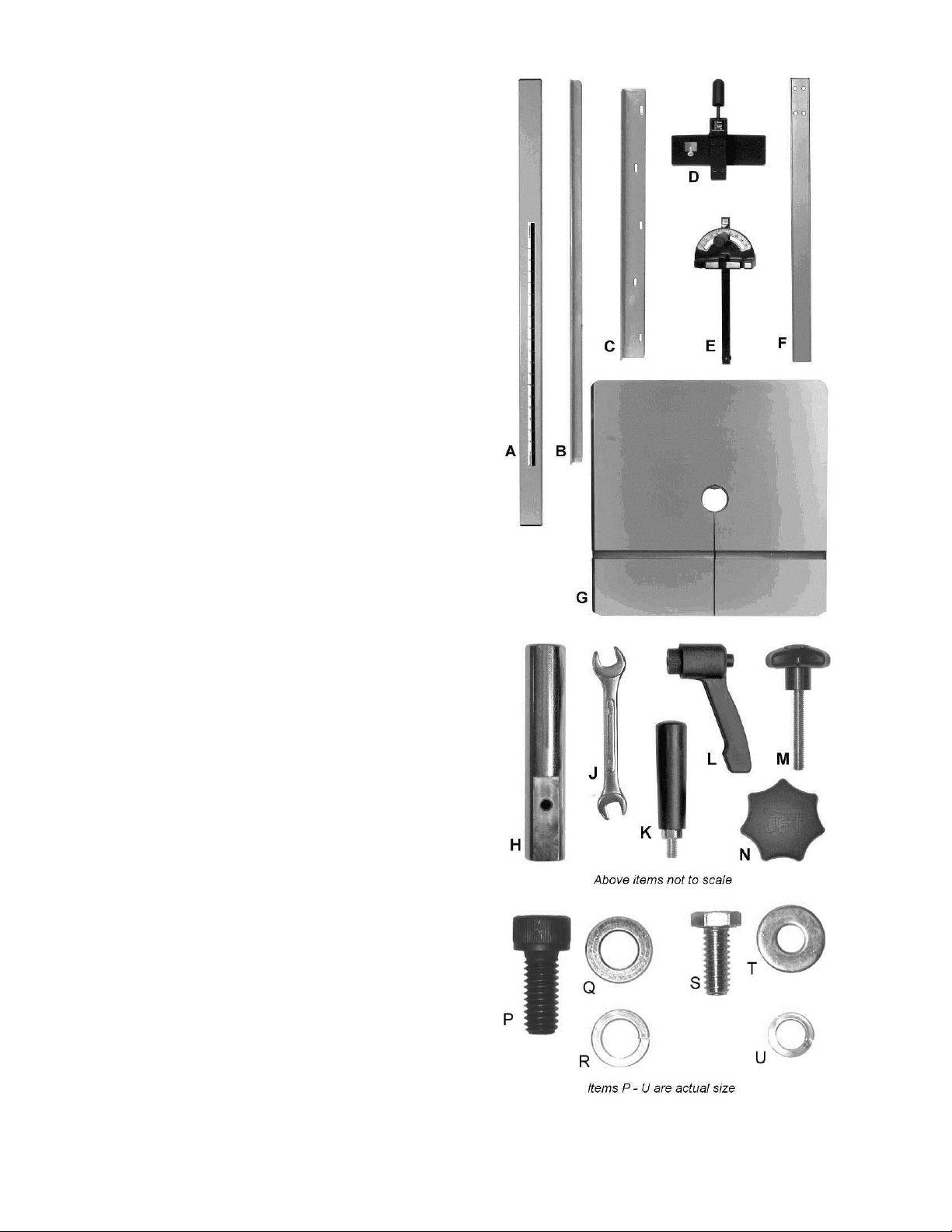
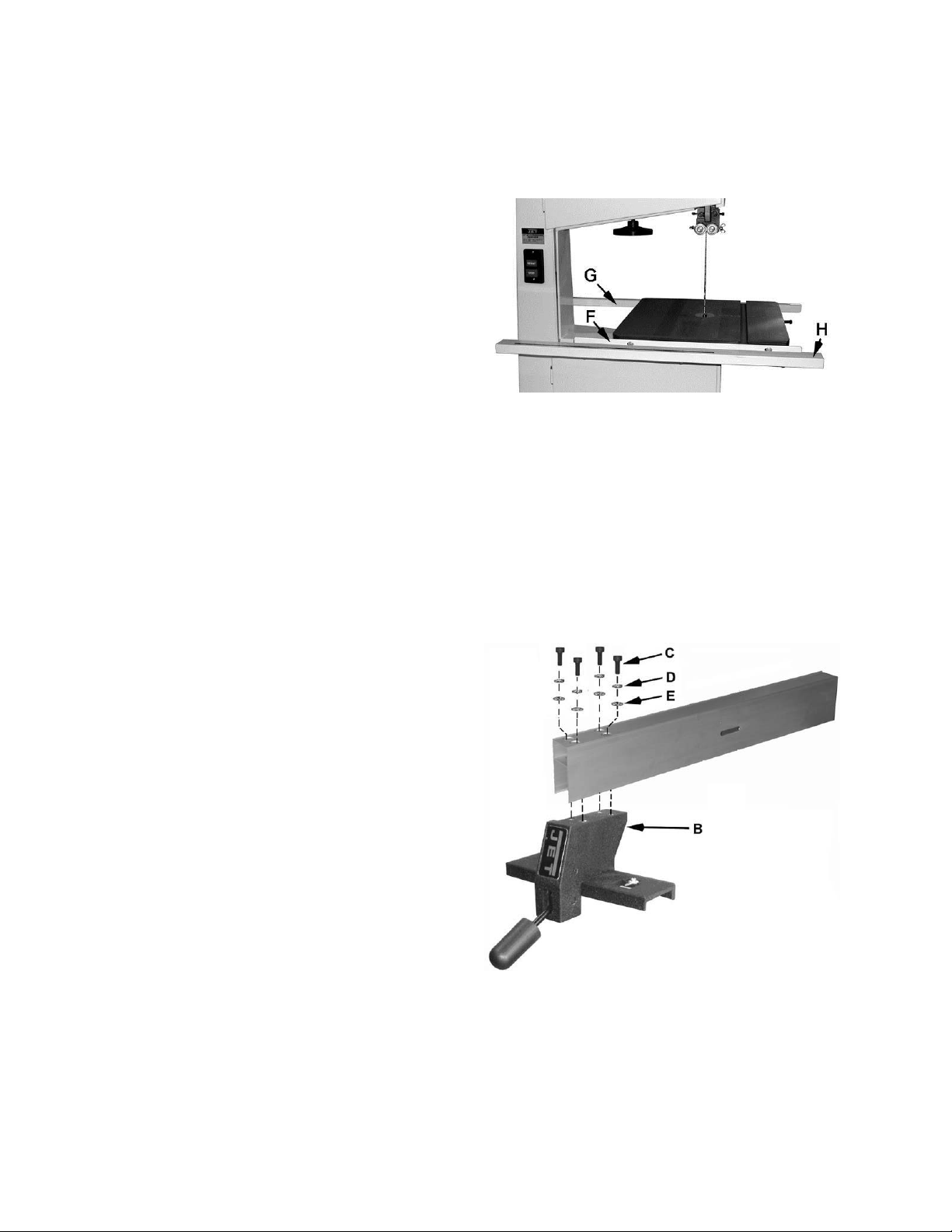
Contents of Shipping Container
1 Band Saw (not shown)
1 Rail Guide ( A )
1 Rear Rail (B )
1 Front Rail (C)
1 Fence Body (D)
1 Mit er G auge (E)
1 Fence (F)
1 Table (G)
1 Accessory Package Contains:
Hardware Bag
01 0Resaw P ost (H )
01 010/12mm Open End Wrench (J)
01 0Handle (K)
01 0Lock Handle (L) – JWBS-20QT only
01 0Resaw Post Lock Knob (M)
01 0Lock Knob (N) – JWBS-20QT only
02 0Lock Knob (N) – JWBS-18QT only
Fence Hardwar e Bag
04 5/16-18x3/4 Socket Head Cap Screws (P)
04 5/16 Flat Washers (Q)
04 5/16 Lock Washers (R)
Rail Hardware Bag
09 1/4-20x5/8 Hex Cap Screws (S)
09 1/4 Flat Washers (T)
09 1/4 Lock Washers (U)
1 Owner’s Manual ( not shown)
1 Warranty Card (not shown)
Tools Required for Assembl y & Adj ustments
The tools listed below are not included but are
required for assembly.
2 14mm Open End Wr enc h
1 Cross Point S crew Driv er
1 Combination Square
Figure 3 - Hardware
9
Page 10
Assembly
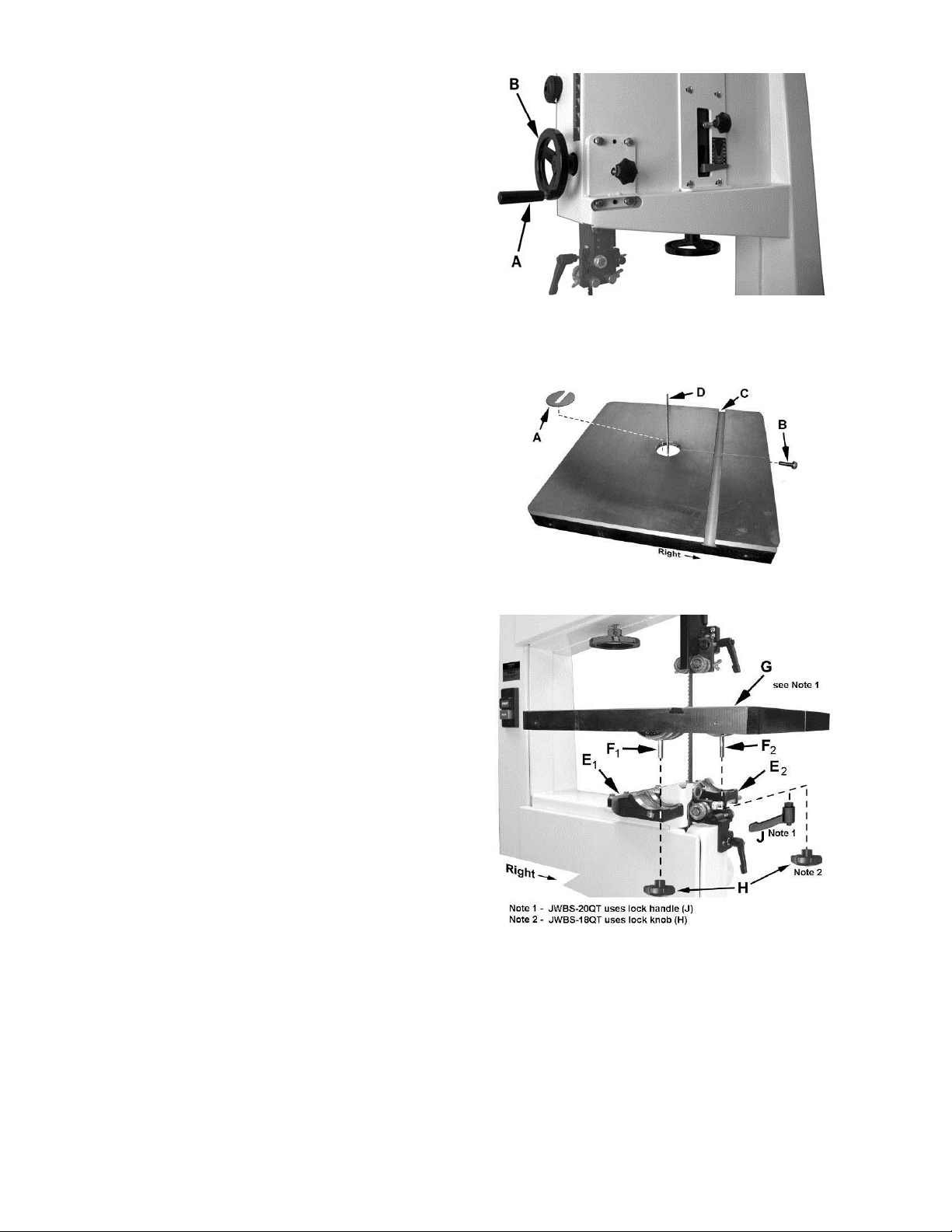
Handwheel
Attach the handle (A, Fig. 4) to the handwheel
(B, Fig. 4) .
Mounting the Table
Important: The table is heavy. Mounting with the
help of another person is recommended.
Referring to Fi gur es 5 and 6:
1. Remove the table insert (A) and tapered
pin (B).
2. Slide the table so the saw blade (D) passes
through the slot where the tapered pin (B) was
located.
3. Rotate the table 90 degrees so that the miter
slot (C) is parall el to the blade (D) and to the
right of the blade when f acing the band saw as
viewed in Figure 6.
Figure 4
Figure 5
4. Line up the table (G) to the trunnions so that
the bolts (F
bracket (E
, F2) feed through the support
1
, E2).
1
For band saw model JWBS- 18QT
Secure the table with two lock knobs (H).
For band saw model JWBS- 20QT
Secure the table with lock knob (H) to bolt F
and lock handle (J) to bolt F
.
2
5. Reinstall the table insert (A) and tapered
pin (B).
1
Figure 6
10
Page 11
Rail Assembly
Referring to Fi gur e 7:
1. Attach the front rail (F) to the cast iron table
with two 1/4” x 5/8” hex cap screws, two 1/4”
lock washers, and two 1/4” flat washers. The
screws should be in approximately the center
of the slot. Hand-tighten only at this time.
2. Attach the rear rail (G) to the table with two
1/4” x 5/8” hex cap screws, two 1/4” lock
washers, and two 1/4” flat washers. Screws
should be in approximately the center of the
slot. Hand-ti ghten only at this time.
3. Push the front and rear rails up as far as they
will go.
4. Using a 10mm wrench, tighten the four hex cap
screws holding the front and rear rails to the
table. Do not over -tighten the screws.
5. Attach the guide tube (H) to the front rail with
five 1/4” x 5/8” hex cap screws, five 1/4” lock
washers, and five 1/4” flat washers. Screws
should be in approximately the center of the
slot.
Hand-tighten the guide tube only at this time.
You will be instructed to secure it later in the
Fence Assembly and Adjust m ent section.
Fence Assembly and Adjustment
Assembling the F enc e to F enc e Body
Referring to Fi gur e 8:
1. Attach the fence (A) to the fence body (B) wi th
four 5/16” x 3/4” socket head cap screws (C),
four 5/16” lock washers (D), and four 5/16” flat
washers (E). Hand-tighten only at thi s time.
Figure 7
Figure 8
11
Page 12
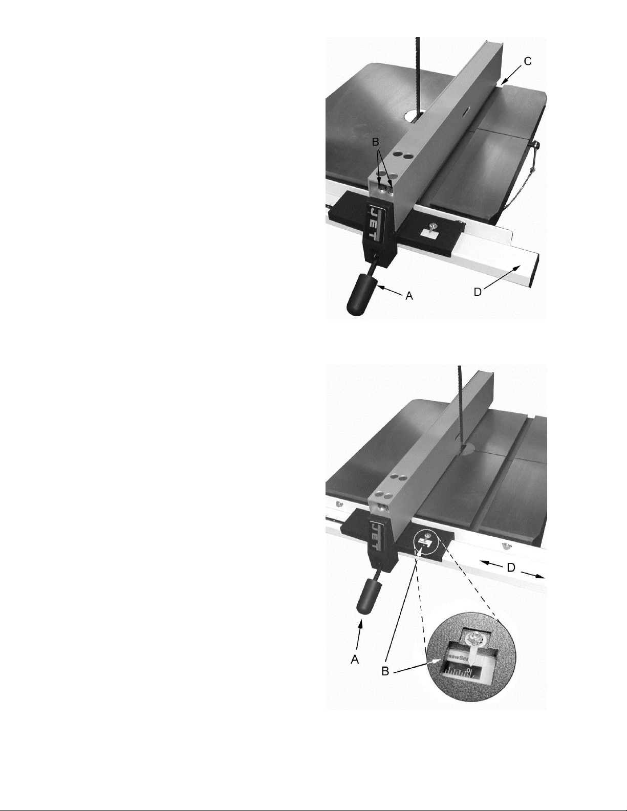
Fence Adjustm ent
2. Place the fence assembly onto the guide
rail (D, Fig. 9) and against the edge of the miter
slot (C, Fig. 9). The hook at the rear of the
fence should f it under the rear rail (see Figure
12).
The fence must ali gn parall el to t he miter slot along
the entire l ength of the fence.
If adjustm ent is necessary:
3. Lock the fence by pushing down the lock
handle (A, F ig. 9). Because the scre ws are only
hand-tight, you can shift the fence slightly as
needed until the fence is parallel the miter slot.
4. When the fence has been properly aligned to
the miter slot, t ighten t he four socket head cap
screws (B, Fig. 9) with a 6mm hex wrench.
Make sure the fence remains parallel to the
miter slot as you ti ghten the screws.
Note: This alignment will again be checked
once the guide rail has been tightened.
5. Move the fence assembly to the other side of
the blade as shown in Figure 10 so that the
pointer (B, Fi g. 10) on the f ence body point s to
zero on the scale. Lock the fence by pushing
the handle (A, Fig. 10) down.
Figure 9
6. Mov e the guide rail (D, Fig. 10) with the lock ed
fence until t he fence is flush against the bl ade
(C, Fig. 10). Do not unlock the fence t o perform
this. Move the fence and guide rail together
when establishing the zero point.
Important: Do not force the fence into the
blade so that the blade bends.
7. With a 10mm wrench, t ighten the five hex cap
screws located on the bottom of the front rail
that hold the guide rail to the front rail.
Note: After tightening the guide rail, double
check that the f ence is still parallel to the miter
slot. Make additional adjustments if needed.
Figure 10
12
Page 13
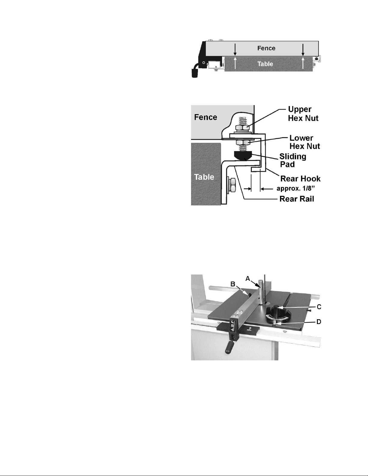
Adjusting Clearance between Fence and Table
Referring to Fi gur es 11 and 12:
Check the clearance between the table and the
fence. The fence should not rub against the table
surface but be sli ghtly above it. Thi s gap should be
the same at the front of t he table as it is at the rear.
If the gap between fence and table is not
consistent, loosen either of the hex nuts on the
hook (Figur e 12) and rot ate the sliding pad unt il the
fence/tabl e gap is consistent acr oss the full lengt h
of the table. When this is achieved, tighten both
hex nuts.
Check the adjustment of the hook at the rear of the
fence. The hook should be positioned so that it
overlaps the rear rail by approximately 1/8”
(Fig. 12). To adjust the hook, loosen t he upper hex
nut and slide the hook in or out as needed. Retighten upper hex nut.
Resaw Guide
For resawing attach the post (A, Fig. 13) to the
fence with the lock knob (B, Fig. 13). There is a
slotted hole in the fence that will accommodat e the
resaw kit. Position the post so that it is centered
with the front edge of the blade. The resaw guide
will give you a taller, single point contact surface
during resawing.
Figure 11
Figure 12
Miter Gauge
1. Place the miter gauge i n the t able slot.
2. With a square verify the miter gauge face is
square to the blade.
3. If the miter gauge is not square to the blade
loosen the lock knob (C, Fig. 13) and adjust t o
the proper setting. Tighten the lock knob.
4. If the pointer is not at 90 degrees, loosen the
screw (D, Fig. 13) holding the pointer and mov e
the pointer to 90 degr ees.
5. Re-tighten the screw.
Figure 13
13
Page 14
Adjustments
Table Tilt
Referring to Fi gur e 14:
1. Disconnect machine from power source.
2. Loosen the lock k nob( s ) /lock handle (G).
3. Til t table up to 45 degr ees to the right, or up to
10 degrees to the left.
4. Tighten the lock knob(s)/lock handle.
Note: Tabl e stop bolt (F, Fig. 14) must be removed
to tilt table to the left.
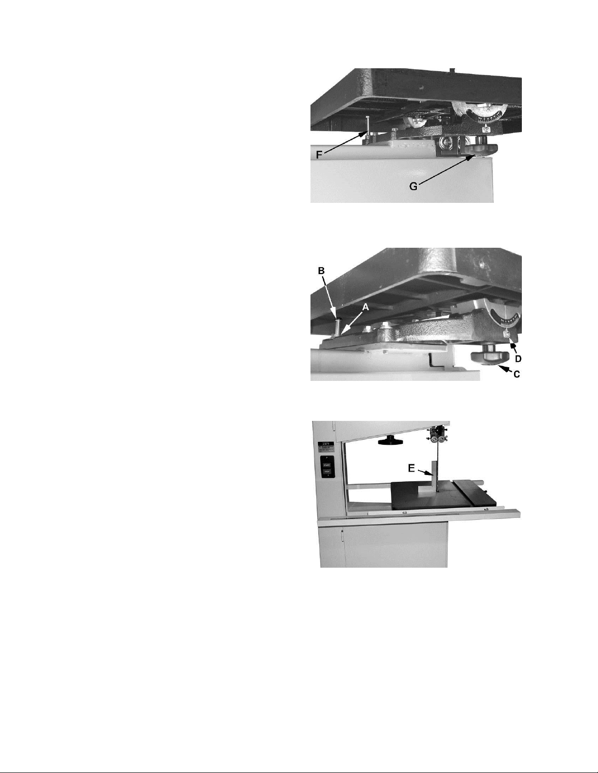
Adjusting 90 Degree Table Stop
Before adjusting the 90º table stop, the blade
tension must be pr operl y adjusted (descri bed i n the
Blade Tension section).
To adjust the 90º table stop:
1. Loosen lock knob(s)/lock handle (C, Fig. 15)
and tilt the table until it rests against tabl e stop
bolt (B, Fig. 15); then re-tighten the lock
knob(s)/handle.
2. Use a square (E, Fig. 16) placed on the table
and against the bl ade to see if the table is 90
degrees to the blade.
3. If an adjustment is necessary, l oosen the lock
knob(s)/handle (C, Fig. 15). Til t the table until it
is square to the blade; then re-tighten the lock
knobs.
Figure 14
Figure 15
4. Loosen lock nut (A, Fig. 15) and t urn tabl e stop
bolt (B, Fig. 15) until it contacts the table.
Tighten t he nut (A, Fig. 15) to hold t able stop in
place. When tightening the nut hold the table
stop bolt in place with a wrench to prevent
movement.
5. If necessary, adjust the pointer (D, Fig. 15) to
zero.
Figure 16
14
Page 15
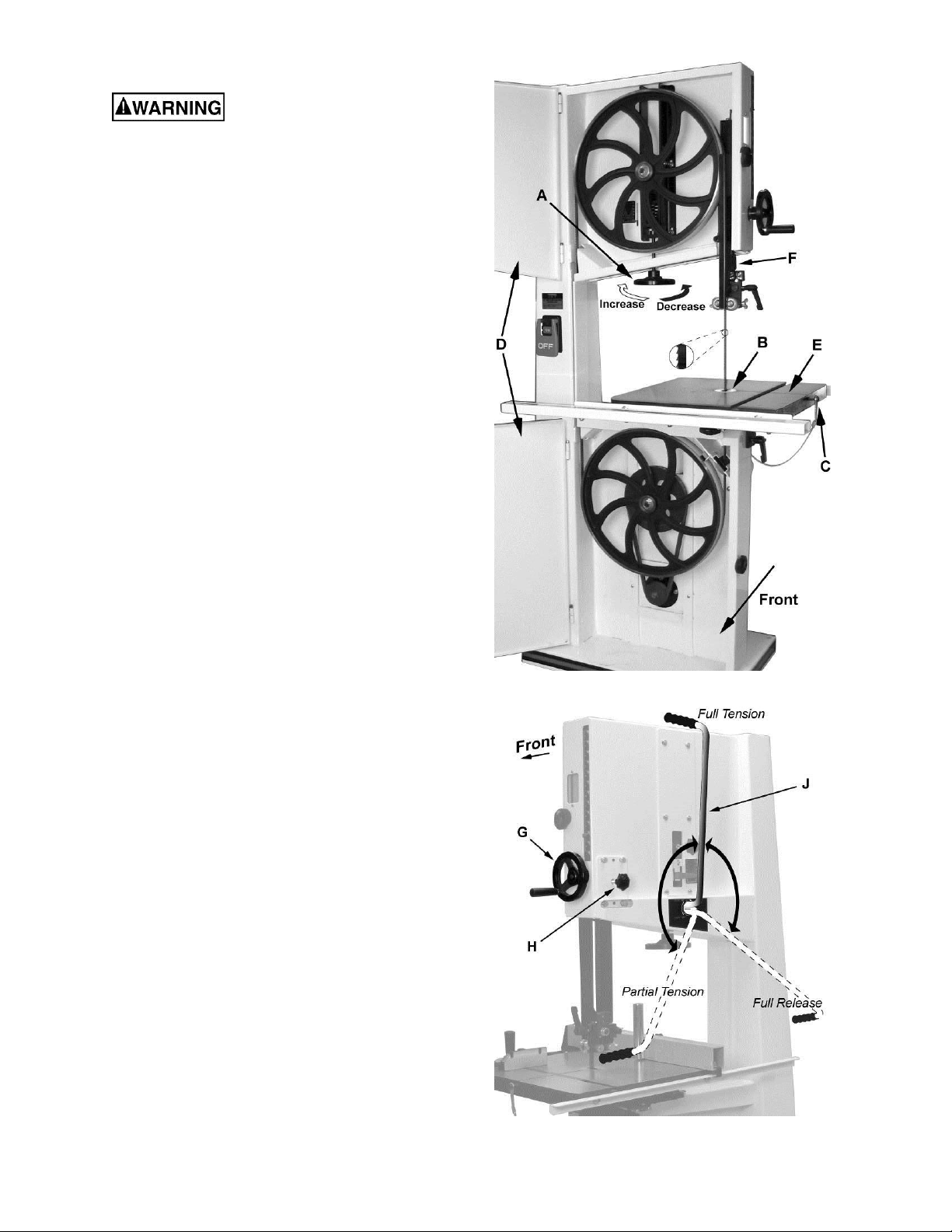
Installing/Changing Blades
Disconnect machine from
power source. Blade teeth are sharp, use care
when handling the blade. Failure to compl y may
cause serious inj ury.
1. Disconnect machine from power source.
2. Place the mode selection lever (J, Fig. 18) in
the Full Release (Blade Change) position.
Note 1: When changing the position of the
mode selection lever, the machine must be
turned off.
Note 2: The blade tension handwheel
(A, Fig. 17) is primarily used for initial blade
tension adjustments (described on following
page).
3. Remove the table ins ert (B, Fig. 17).
4. Remove the tapered pin (C, Fi g. 17) by using
the wrench attached t ogether with the pin.
5. Lower the upper blade guide assembly
(F, fig. 17) by loosening the knob (H, Fig. 18)
and rotating the handwheel ( G, Fig. 18) clockwise.
6. Open upper and lower front doors (D, Fig. 17).
7. Carefully remove the blade from between
upper and lower blade guides and upper and
lower wheels; then remove blade through the
table slot (E, Fi g. 17).
8. Guide new blade through table slot (E, Fig. 17) .
Place blade in upper and lower blade guides.
Note: Make sure blade teeth point down
toward table (see inset, Fig. 17), and toward
the front of the saw.
Hint: If the teeth cannot be made to point
down, try turning t he blade inside out first, then
reattempt.
9. Posit ion blade on the middle of the upper and
lo wer wheels.
10. Replace t he table insert (B, Fig. 17) and
tapered pin (C, Fi g. 17).
11. Pl ace the lever (J, Fig. 18) to the F ull Tension
or Partial Tension (Idle/Track ing) posi tion.
Before operating the band saw, the new blade must
be adjusted and blade guides re-adjusted. The
required adj ustments are contained in the sections
listed below and which follow immediately:
Figure 17
Blade T ensi on ( page 16)
Blade Track ing (page 16)
Upper Beari ng A djustment (page 17)
Lower Beari ng A djustment (page 18)
Figure 18
15
Page 16
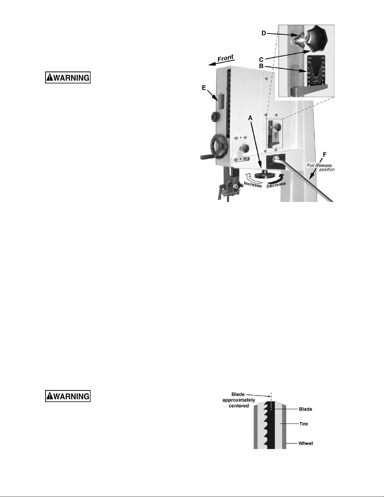
Blade Tension
Blade tension is set with the blade tension
handwheel (A, Fi g. 19) and is performed following
blade replacement and periodically as the blade
stretches fr om use.
Disconnect machine from
power source before maki ng any adjustments.
Referring to Fi gur e 19:
1. Place the mode selection lever (F) in the Full
Tension posit ion (see Figure 18).
2. Set the blade tension by rotating the
handwheel (A) according to the arrow
directions shown in F igure 19.
The gauge (B) indicates the approximate
tension according to the width of the blade in
inches. Initially, set the blade tension to
correspond to the width of your blade.
The JWBS-18QT comes with a 3/4" blade so
the tension should be set at 3/4" when using
this blade.
The JWBS-20QT com es with a 1" blade so the
tension should be set at 1" when using this
blade.
Note: For the JWBS-18QT the tension gauge
can also be seen from the front of the saw
through the wheel when the upper door is open.
As you become fami liar with the saw, you m ay fi nd
it necessary to change t he blade tension fr om the
initial setting.
Keep in mind that too little or too much blade
tension can cause blade breakage and/or poor
cutting perf ormance.
Tip: When the band saw is not being used, pl ace
the mode selection lever (J, Fig. 18) to the Partial
Tension posit ion – this will prolong the blade’s l ife.
Blade Tracking
Tracking refers to the position of the saw blade on
the wheels while the machine is in operation.
Tracking has been factory-adjusted. However, it
should be checked occasionally, including after
every blade change.
Figure 19
1. Open upper front door to expose the wheel.
Rotate the wheel clockwise by hand and
observe the positi on of the blade on the wheel
through the window (E, Fig. 19). The blade
should ride upon the center of the wheel as
shown in Figure 20.
2. If t he blade tends to move toward the edge of
the wheel, loosen the wing nut (D, Fig. 19) and
slightly rotate the knob (C, Fig. 19). Rotating
the knob clockwise will cause the blade to
move toward the rear edge of the wheel.
Rotating the knob counterclockwise will cause
the blade t o mov e toward the f ront edge of the
wheel.
Note: This adjustment is sensitiv e; perform it in
small increments and give the blade time to
react to the changes as you cont inue to rotate
the wheel.
3. When the blade is tracking properly in the
center of the wheel, re-tighten the wing nut
(D, Fig. 19).
4. Close the upper front door.
Disconnect machi ne f rom
power source before maki ng any adjustments.
Important: The blade must be in Full or Partial
Tension positions before adjusting blade tracking
(see previous secti on). Make sure the blade guides
and other parts of the machine will not interfere
with the movement of the blade.
To inspect and adjust t r ac ki ng, proceed as follows:
Figure 20
16
Page 17

Overview – Bearing Adjustments
Thrust (back support) bearing are located behind
the saw blade and provide support to the back of
the blade when the saw is in operation.
Guide bearings are located on either side of the
saw blade and provi de stabili ty for the blade when
the saw is in operation. These bearings rotate on
an eccentric shaft so the distance from the blade
can be adjusted for optimal performance.
Upper Bearing Adjustments
Unplug the machine from power
source before making any adjustments! Blade
teeth are sharp - use care when working near
the saw blade. Failure to comply may cause
serious injury.
Note: Blade tensi on and tracking must be pr operly
adjusted prior to beari ng guide setup. Refer to the
Blade Tension secti on ( pr ev ious page).
To adjust the thrust bear ing:
1. Place the mode selection lever (J, Fig. 18) in
the Full Tens ion position.
Referring to Fi gur e 21:
2. Loosen the wing nut (E) and slide the bearing
and bearing post until the space between the
thrust bearing (H) and the back edge of the
blade (G) is approxim ately 1/64”.
A convenient way to achieve this spacing i s by
placing a dollar bill folded twice (four
thicknesses) between the blade and support
bearing – four thicknesses of a dollar bill is
approxim ately 1/64”.
3. Tighten wing nut (E).
To adjust the guide bear ings (refer to Figure 22):
4. Loosen the locking handle (L) and slide the
assembly until the front of the guide bearings
rest just behind the gullet of the blade teeth
(see inset).
5. Loosen two wing nuts (J
, J2). Rotate the
1
adjustment handles (M) until the guide bearings
(K) rest lightly against the blade (N). Do not
force the guide bearings agai nst the side of the
blade.
6. Tighten wing nuts (J
, J2 Fig. 22).
1
Check to make sure the adjustments have not
changed and the bearing guides do not pinch the
blade.
Place the mode selection lever (J, Fig. 18) in the
Partial Tension posit ion when the machine i s not in
use.
Figure 21
Figure 22
17
Page 18

Lower Bearing Adjustments
Unplug the machine from power
source before making any adjustments! Blade
teeth are sharp - use care when working near
the saw blade. Failure to comply may cause
serious injury.
Note: Blade tensi on and tracking must be pr operly
adjusted prior to beari ng guide setup. Refer to the
Blade Tension secti on ( page 16) .
1. Place the mode selection lever (J, Fig. 18) in
the Full Tens ion position.
Referring to Fi gur e 23:
2. Loosen the thum b s c r ew (B).
This will allow the thrust bearing (A) to move
freely and prevent interference with the saw
blade (C) during t he following steps.
Guide Gearings Adjustment
3. Loosen the locking handle (D) then turn the
adjustment screw (E) to adjust the assembly
forward or backward until the front of the guide
bearings (F) rest just behind the gullet of the
blade teeth (C and inset).
4. Tighten the locking handle (D).
Thrust Bearing Adjustment
5. With the thumb screw still loose (f rom Step 1),
slide the thrust bearing and bearing post until
the space between the bearing (A) and the
back edge of the blade (C) is approximately
1/64”.
A convenient way to achieve this spacing i s by
placing a dollar bill folded twice (four
thicknesses) between the blade and support
bearing – four thicknesses of a dollar bill is
approxim ately 1/64”.
6. Tighten the thumb s crew (B) .
7. Loosen the lock knob (G). Rotate the
adjustment handles ( H) until t he guide bearings
(F) rest lightly against the blade (C). Do not
force the guide bearings agai nst the side of the
blade.
8. Tighten the lock knob (G) .
Check to make sure the adjustments have not
changed and the bearing guides do not pinch the
blade.
Place the mode selection lever (J, Fig. 18) in the
Partial Tension posit ion when the machine i s not in
use.
Figure 23
18
Page 19

Blade Lead
Blade drift (also known as lead or fence drift) is a
problem that may occur when the blade begi ns to
wander off the cutting line even when the band saw
fence is being used. Figure 24 shows an exam ple
of blade lead.
Blade lead can be caused by a num ber of factors,
and these should all be checked and corrected if
necessary:
Fence is not parallel to miter slot and
blade.
Blade is not t ensi oned c orrectly.
Blade is dull.
Teeth have too much “set” on one side of
the blade.
If replacement of the blade is not currently an
option, the bl ade lead can be compensated f or by
skewing the fence. Proceed as follows:
1. Cut a scrap piece of wood about the same
length as the band saw table, and joint one
edge along its length, or rip it on a table saw to
give it a straight edge.
2. Draw a line on the board parallel with the
jointed, or str aight edge of the board.
3. Move the band saw f ence out of the way, and
carefully make a freehand cut along your drawn
line on the board. Stop about midway on the
board, and shut off the band saw (allow the
blade to come to a complete stop) but do not
allow the board t o move.
4. Clamp the board to the table.
5. Slide the band saw fence over against the
board until it contacts the straight edge of the
board at some point. Lock the fence down.
6. Loosen the four hex cap screws at the top of
the fence (see Figure 9) and shift the fence
until it is parallel to the board along its length.
7. Re-tighten the four hex cap screws.
Note: Skewing the fence to correct blade lead is
effectiv e for that particular blade; when a new blade
is installed, the fence will probably need readjustment.
Figure 24
19
Page 20

Changing the Blade Speed
Disconnect machi ne f rom
power source before maki ng any adjustments.
The JWBS-18QT and -20QT band saw has two
blade-speed options which is determined by the
position of the pulley drive belt. Refer to the
Specifications section (page 6) for speed specs.
To change the blade speed (while referring to
Figure 25):
1. Loosen the lock handle (A) that secures the
motor (C).
2. Release belt tension by pulling handle (B) up
which raises the motor, then tighten lock
handle (A).
3. Open the lower wheel door (C, Fig. 27).
4. Referring to Fi gur e 26:
For higher blade-s peed – place t he poly V-belt
in the A position on the spindle and motor
pulleys as shown in Figure 26.
For lower blade-speed – place the poly V-belt
in the B position on the spindle and motor
pulleys.
Figure 25
After repositioning the belt:
5. Unlock lock handle (A, Fig. 25). Apply belt
tension by sli ghtly pushing handle (B, Fi g. 25)
down.
6. Tighten the lock handle (A, Fig, 25) to secure
the motor (C, Fig. 25).
Belt Tension
The drive belt and pulleys are properl y adjusted at
the factory. However, belt tension should be
occasionally checked. The belt will need to be retensioned after belt replacement.
Disconnect machi ne f rom
power source before maki ng any adjustments.
Referring to Fi gur e 25:
1. Loosen the lock handle (A) that secures the
motor (C).
2. Set the belt tension by lightl y pressing down on
the handle (B).
Figure 26
3. Tighten the lock handle (A).
Note: A new belt may stretch slightly during the
“breaking in” process, and the tension may
occasionally need to be checked and adjusted.
The weight of the motor should put enough
tension on the belt. You just want to push down
lightly to take up any slack.
Place the mode selection lever (J, Fig. 18) in the
Partial Tension posit ion when the machine i s not in
use.
20
Page 21

Replacing the Poly V-Belt
Disconnect machi ne f rom
power source before maki ng any adjustments.
1. Place the mode selection lever (J, Fig. 18) in
the Full Release posi tion.
Referring to Fi gur e 25:
2. Loosen the lock handle (A) that secures the
motor (C).
3. Release belt tension by pulling handle (B) up
which raises the motor, then tighten lock
handle (A).
4. Open the lower wheel door (C, Fig. 27) and
remove the hex nut and washer ( D, Fi g. 27) .
5. Remove the wheel (E, Fig. 28). If the lower
wheel does not com e off easily you may need
to use a pulley puller to rem ov e it.
Note: If you are doing a pulley alignment only, skip
Step 6.
6. Remove the old belt (F, Fig. 28) and install the
new belt.
Note: For higher blade-speed, place the belt on
the pulleys cl osest to the motor (A, Fig. 26). For
lower blade-speed, place the belt on the
pulleys away f r om the motor (B, Fi g. 26).
Since the wheel is still off, this is the most
convenient time to check the wheel and motor
pulley alignment. Jump to the Pulley Alignment
procedure (following page) at this time. At the
conclusion you will be redirected back here.
After the pulley alignment (if performed) is
complete:
7. Reinstall the lower wheel, hex nut and washer
and tighten the hex nut.
8. Unlock lock handle (A, Fig. 25). Apply belt
tension by sli ghtly pushing handle (B, Fi g. 25)
down.
9. Tighten the lock handle (A, Fig, 25) to secure
the motor (C).
Important: Before operati ng the band saw, refer t o
the sections listed below and perform the requir ed
adjustments described in them.
Installing/Changing Blades (page 15)
Belt Tensi on ( below)
Blade T ensi on ( page 20)
Blade Track ing (page 16)
Upper Beari ng A djustments (page 17)
Lower Beari ng A djustments (page 18)
Figure 27
Figure 28
21
Page 22
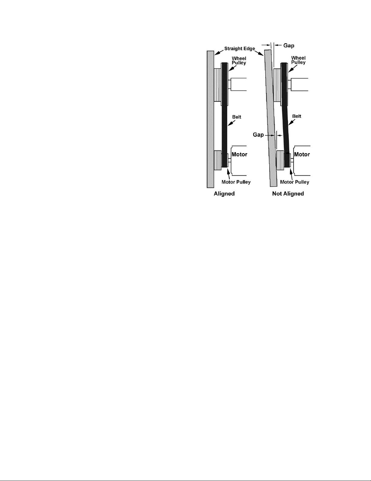
Pulley Alignment
The pulley ali gnment is done in conjunc tion with the
poly V-belt replacement.
If you are just beginning the alignment, start with
the Replacing the Poly V-Belt section (previous
page.
If you were directed her e, proceed as follows:
1. Uses a straight edge placed agai nst the wheel
pulley and motor pull ey and refer to Figure 29
to determine if alignm ent is necessary.
If alignment is necessary:
2. With a 4mm hex wrench, l oosen two set screws
on the motor (lower) pulley.
3. Adjust the motor pulley by sliding in or out.
4. Confirm the alignment of the poly V-belt by
placing a straight edge against the faces of
both pulleys, (Figure 29). If the straight edge
lies flush against bot h pulleys, then the pull eys
and belt are aligned.
5. Re-tighten the two set screws on the motor
pulley.
Return to Step 7 of the Replacing Poly V-Belt
section on page 21.
Figure 29
22
Page 23

Operating Controls
Start/Stop Switch
The switch shown in Fi gure 30 i s used on model
JBWS-18QT band saw.
Press the green on button (A, Fig. 4) to start.
Press the red saf ety switch off button (B, Fig. 4)
to stop.
Figure 30 – Start/ Stop Sw itch
Safety Key – The magnetic Start/Stop switch
comes equipped with a magnetic safety key.
When in position on the switch as shown in
Figure 31, the magnetic safety key trips a relay
which will allow the machine to start and stop
when the respective switches are pressed.
Being magnet ic, t he safety key can be removed
to make the machine inoperable and can be
hidden for safe storage by attaching it
underneath the rail or another magnetic surface.
When using a saw equipped with this switch,
place the safety key on the switc h cover , lining
up the arrow on the key with the REMOVE arrow
on the cover. T hen rotate the key so the arrow
lines up with the LOCK arrow. This will prev ent
the safety key from c oming loose from v ibration
when the machine is i n use.
The switch shown in Figure 31 is a magnetic
switch used on the JBWS-18QT-3 and all
JBWS-20QT model band saws.
Power Indicator Light – The start switch has a
power indicator lamp which is on whenever
there is pow er connected to the band saw, not
just when the band saw is running. Do not
assume that no light means t here is no pow er t o
the machine. If the bulb is bad, there will no
indication. Always check before use.
Do not rely that no light
means no power to the machine. Always
check for power first. Fail ure to comply may
cause serious inj ury!
To operate the magnetic Start/Stop switch
(referring also to Figure 31):
Start – Press the green start switch.
When power is connected to the machine, the
green light is always on regardless of whether
the band saw is running or not .
Stop – Press the red switch to stop.
Figure 31 – Magnetic Star t/ S top Switch
Brake Pedal (JWBS-20QT only)
Press the brake pedal (A, Fig. 32) while the saw
is running to stop t he saw. Re-start the saw by
pressing the on switch.
Reset – In the event that the band saw stops
without pressing the stop but ton, as the resul t of
a tripped fuse or ci rcuit br eak er , etc.:
1. Press red button to reset
2. Press the green button to restart the
machine.
Figure 32 – Brake Pedal
23
Page 24

Operation
Note: The following Figures may or may not
show your particular band saw model, but the
procedures are identic al.
General Procedure
1. Make sure the blade and upper and lower
bearings are properly adjusted for tension
and tracki ng.
2. Adjust blade guide assembly so that the
guide bearings are just above the workpiece
(about 3/16”) all owing minimum exposure to
the blade. See Figur e 33.
3. If using the f ence, m ove it int o position and
lock it t o the guide rail. If you are usi ng the
miter gauge for a crosscut, t he fence should
be moved safely out of the way.
Ripping
Ripping is cutting lengthwise down the
workpiece, and with the grain (of wood stock).
See Figure 34.
Figure 34
4. Turn on the band saw and allow a few
seconds for t he machine to reach full speed.
Whenever possible, use a
push stick, hold-down, power feeder, jig, or
similar device while feedi ng stock, to prevent
your hands getting too close to the blade.
5. Pl ace the straightest edge of the workpiece
against the fence, and push the workpiece
slowly into the blade. Do not force the
workpiece int o the blade.
When cutting, do not
overfeed the blade; overfeeding will reduce
blade life and may cau se the bl ade to break.
6. When cutting long stoc k , the operator should
use roller stands, support tables, or an
assistant to help stabilize the workpiece.
Crosscutting
Crosscutting is cutting across the grain of the
workpiece, while using the miter gauge to feed
the workpiece i nto the blade.
Slide the bar of the miter gauge into the end of
the slot on the table.
The right hand should hold the workpiece steady
against the miter gauge, while the left hand
pushes the miter gauge past the blade, as
shown in Figure 35.
Do not use the fence in conjunction with the
miter gauge. The offcut of the workpiece must
not be constrained during or after the cutting
process.
Using the fence in
conjunction with the miter gauge can cause
binding and possible damage to the blade.
Figure 33
Figure 35
24
Page 25

Resawing
Resawing is the process of slicing stock to
reduce its thickness, or to produce board s that
are thinner than the original workpiece.
Figure 36 demonstr ates resawing.
The ideal blade for resawing is the widest one
the machine c an handle, as the wider the bl ade
the better it can hold a str aight line.
When resawing thin stock, use a push block,
push stick, or similar device to keep your hands
away from the blade.
the tip of the tooth. Generally, wider blades are
used for ripping or making straight cuts;
narrower blades are often used when the part
being cut has curves with small radii. When
cutting straight lines with a narrow blade, the
blade may have a t endency to wander, causing
blade lead. (refer to the Blade Lead section in
Adjustments).
Pitch
Pitch is measured in "teeth per inch" (TPI).
Figure 37 shows blades with diff erent pitc hes. A
fine pitch (more teeth per inch) will cut slower
but smoother. A coarse pitch (fewer teeth per
inch) will cut rougher but faster. As a rule of
thumb, the thicker the workpiece, the coarser
will be the blade pitc h. If you have to cut a hard
or very brittle material, you will probably want to
use a blade with a finer pitch in order to get
good clean cuts.
General rule: Use a blade that will have no
fewer than 6 and no more than 12 teeth in the
workpiece at any given time.
Figure 36
Saw Blade Selection
Using the proper bl ade for the job will incr ease
the operating efficiency of your band saw, help
reduce necessary saw maintenance, and
improve your productivit y. Thus, it is important to
follow certain guidelines when selecting a saw
blade.
Here are factors to consider when selecting a
blade:
The type of material you will be cutting.
The thick ness of the workpiece or part.
The features of the workpiece or part,
such as bends or curv es with small radii.
These factors are important because they
involve basic concepts of saw blade design.
There are five (5) blade features that are
normally changed to meet certain kinds of
sawing requirements. They are:
1. width
Figure 37
Shape
Figure 38 shows common types of tooth shape.
Tooth shape has an effect on cutting rate, and
with few exceptions, the Skip and Hook types
are used to obtain higher feed rates when
cutting thick workpieces. Variable-tooth blades
are also available, which combine features of
the other styles.
2. pitch (number of teeth per inch),
3. tooth form (or shape),
4. the "set" of the teeth
5. the blade material itself.
Width
Band saw blades come in different standard
widths, measured f rom the back of the blade to
Figure 38
25
Page 26

Set
The term "set" refers to the way in which the
saw teeth are bent or positioned. Set patterns
are usually selected depending on the type of
material that needs to be cut. Three common set
patterns are shown in Figure 39.
Generally, the Raker set is used for cutting
metal workpieces; the Wave set, when the
thickness of the workpiece changes, such as
cutting holl ow tubing or structural s. The Straight
set is most oft en pref erred when cutt i ng wood or
plastics.
1. Misalignment of the blade guides
2. Feeding work too f ast
3. Using a wide blade to cut a short radius
curve
4. Excessive tension
5. Teeth are dull or impr oper ly set
6. Upper guides are set too high off the
workpiece
7. Faulty weld on bl ade
Maintenance
Before any intervention on
the machine, disconnect it from the electrical
supply by pu lling out the plug. Failure to
comply may cause seriou s injury.
Keep bearing guides clean and free of build-up.
Check that the cleaning brush over the band
wheel is working properly, and remove any
deposits from the band wheels to av oid vi br ation
and blade breakage.
Figure 39
Material
Band saw blades can be made from different
types of materials. Some of the most common
include spring steel, carbon steel, carbon steel
equipped with a hi gh speed or welded edge (bimetal), or carbide tips. A special type of saw
blade is made from "high speed steel"; these
should not be used on band saws with low rates
of speed.
Because of the im portance of blade sel ection, it
is recommended that you use the Blade
Selection Guide on page 27.
When cutting, do not
overfeed the blade; overfeeding will reduce
blade life, and may cause the bl ade to break.
Blade Breakage
Band saw blades are subject to high stresses
and breakage may sometimes be unavoidable.
However, many f actor s can be controlled t o hel p
prevent most blade breakage. Here are some
common causes for break age:
The table surf ace should be kept clean and f ree
of rust for best results. Some users prefer a
paste wax coating. Another option is talcum
powder applied wit h a blackboard eraser rubbed
in vigorously once a week; this will fill casting
pores and form a moistur e barrier. This method
provides a table top that is slick and allows rust
rings to be easily wiped from the surface.
Important al so is the fact that talcum powder will
not stain wood or mar finishes as wax pickup
does.
Do not let saw dust build up in the upper and
lower wheel housings. Vacuum out frequently.
Connect the band sa w to a JET dust col lection
system.
Clean and grease the raising/lowering rack for
the upper bearing guides if it becom es difficult t o
raise or lower.
Clean and oil the tensioning mechanism if it
becomes diffic ult to adjust.
Vacuum out the motor fan cover.
26
Page 27

Blade Selection Guide
Identify the material and thickness of your workpiec e. The chart will show the recomm ended P ITCH,
blade TYPE, and FEE D RATE.
Key: H – Hook L – Low
S – Skip M – Medium
R – Regular H – High
Example: 10/H/M means 10 teeth per inch / Hook Type Blade / Medium Feed
Workpiec e Thick ness
Material/s
1/2" 1" 3" 6+"
Hardwood 10/R/L 8/R/L 3/H/M 3/H/M
Woods
Softwood 10/R/L 8/R/L 3/H/M 3/H/M
Carbon 10/R/L 6/R/L 3/S/M 3/S/M
NonMetals
Plastics
Mica 32/R/L -- -- -Asbestos 8/R/L 6/R/L 3/S/M 3/S/M
Hard Rubber 10/R/L 8/R/L 6/R/M 2/S/H
Formica 14/R/M 10/R/M 4/H/H 4/H/H
Masonite 10/R/L 4/S/L 3/S/M 3/H/M
Micarta 14/R/M 10/R/M 4/H/H 3/H/H
Plexiglas 10/R/L 6/R/L 3/S/M 3/S/M
Paper 14/R/L 10/R/L 4/S/L 3/S/M
Study the part drawing or prototype, or actually
measure the smallest cutting radius required,
and locate this radius (in inches) on t he chart at
the right. Follow the curve to where the
approxim ate blade width is specified. If a radius
falls between two of the curves, select the
widest blade t hat will saw this radius.
This procedure should be us ed for m aking initial
blade selections. These recommendations can,
of course, be adjusted to meet specific
requirement s of a cutting job. Compromises may
be necessary if you cannot find all needed
specific ations in a single blade.
27
Page 28

Troubleshooting
Trouble Probable Cause Remedy
Saw unplugged Check plug connections
Saw stops or will not
start
Fuse blown, or cir c uit break er tr ipped Replace fuse, or reset circ uit breaker
Cord damaged Replace cord
Does not make
accurate 45
cuts
Blade wanders during
cut
Saw makes
unsatisfactory cuts
o
or 90o
Stop not adjusted corr ec tly
Angle pointer not set accurately
Miter gauge out of adj ustm ent Adjust miter gauge
Fence not ali gned with blade Check and adjust fenc e
Warped wood Select another piece of wood
Excessive f eed r ate Reduce feed rate
Incorrect blade for cut Change blade to corr ec t t y pe
Blade tension not set properly
Guide bearings not set proper ly Review guide beari ng adjustment.
Dull blade Replace blade
Blade mounted wrong Teeth should point down
Gum or pitch on blade Remove blade and clean
Incorrect blade for cut Change blade to corr ec t t y pe
Check blade with square and adjust
stop
Check blade with square and adjust
pointer
Set blade tension acc or ding to blade
size
Blade does not come
up to speed
Saw vibrates
excessively
Gum or pitch on table Clean table
Extension cord too light or too long
Low shop voltage Contact your loc al elec tric company
Base on uneven floor Reposition on fl at, lev el surface
Bad v-belt Replace v-belt
Motor mount is loose Tighten motor mount hardware
Loose hardware Tighten har dware
Replace with adequat e si z e and
length cord
28
Page 29

Parts
Replacement Parts
Replacement par ts are li sted on the f ollowing page s. To order parts or reac h our servi ce depar tm ent, call
1-800-274-6848, Monday t hrough Friday (see our websit e for business hours, www.jett ools.com). Havi ng
the Model Number and Serial Number of your machine availabl e when you call will allow us to serve you
quickly and acc ur ately.
29
Page 30

Upper Wheel Assembly (18QT)
Index No. Part No. Description Size Qty
1 ............... JWBS18D XA-101A ..Saw Body .............................................................................................. 1
2 ............... TS-0152011 .............Carriage Bolt ......................................................5/16-18 x 1 ................. 6
3 ............... JWBS18D XA-103 ....Upper Wheel Bracket, Right Side ........................................................... 1
4 ............... TS-0680031 .............Flat Washer ........................................................5/16 ............................ 6
5 ............... TS-0720081 .............Lock Washer ......................................................5/16 ............................ 6
6 ............... TS-0561021 .............Hex Nut ..............................................................5/16-18 ....................... 6
7 ............... JPS10TS-342 ..........Stop Swi tch Face Plate ......................................for 1.75 HP ................. 1
8 ............... TS-1490151 .............Hex Cap Sc re w ..................................................M8x80 ........................ 1
9 ............... TS-0680021 .............Flat Washe r ........................................................1/4 .............................. 6
10 ............. JWBS18DX-110 .......Sliding B ra c ke t ...................................................................................... 1
11 ............. JWBS18DX-111 .......Blade Tension Indicator Label ................................................................ 2
12 ............. JPS10TS-343 ..........Main Switch ........................................................for 1.75HP .................. 1
13 ............. JWBS18DX-113 .......Shaft Bracket ......................................................................................... 1
14 ............. TS-1541031 .............Nylon Insert Lock Nut .........................................M8 .............................. 1
15 ............. JWBS18DXA-115 ....S pring.................................................................................................... 1
16 ............. JWBS18-116 ............Square Nut ............................................................................................ 1
17 ............. JWBS18DX-117 .......Pointer ................................................................................................... 1
18 ............. JWBS18-118 ............Screw .................................................................M5x8 .......................... 1
21 ............. JWBS18DXA-121 ....Bracket .................................................................................................. 1
22 ............. TS-0050021 .............Hex Cap Screw ..................................................1/4-20 x 5/8 ................ 4
23 ............. JWBS18DX-123 .......Blade Adjusting Screw ........................................................................... 1
25 ............. JWBS18-125 ............Hand Wheel .......................................................................................... 1
26 ............. TS-0267041 .............Set Screw ...........................................................1/4-20 x 3/8 ................ 2
27 ............. TS-0209021 .............Socket Head Cap Screw .....................................3/8-16 x 5/8 ................ 1
28 ............. TS-0720091 .............Lock Washer .....................................................3 /8 .............................. 1
29 ............. JWBS18-129 ............Upper Wheel Shaft ................................................................................ 1
30 ............. BB-6203ZZ ..............Ball Bearing ........................................................6203ZZ
31 ............. JWBS18-131 ............Retaining Ring ....................................................R40 ............................ 2
32 ............. JWBS18-132 ............Upper Wheel ......................................................................................... 1
33 ............. JWBS18DX-133 .......Tire........................................................................................................ 1
35 ............. JWBS18-135 ............Hex Nut ..............................................................5/8-18UNF L.H. .......... 1
36 ............. JWBS18DX-136 .......Blade ……..………………………….3/4"W x 137”L x .026T x 4TPI .......... 1
37 ............. TS-0590061 .............W ing Nut ............................................................5/16-18 ....................... 1
38 ............. JWBS18-138 ............Lock Knob ..........................................................5/16 ............................ 1
39 ............. JWBS18DXA-139 ....Upper Front Door................................................................................... 1
................. JWBS18-139A .........Seal Strip, 29.92”L (not shown) ...........................cut to fit 19.68”............ 1
40 ............. JWBS18-140 ............JET Nameplate ...................................................................................... 1
41 ............. JWBS18-141 ............Warning Label ....................................................................................... 1
42 ............. JWBS18-142 ............Bolt........................................................................................................ 1
43 ............. TS-0561011 .............Hex Nut ..............................................................1/4-20 ......................... 1
44 ............. TS-081C052 ............Screw .................................................................#10-24 x 3/4 ............... 3
44A .......... TS-0050011 .............Hex Cap Screw ..................................................1/4-20 x 1/2 ................ 2
45 ............. JWBS18-39A ...........Door Hinge Pin ...................................................................................... 2
46 ............. JWBS18DXA-146 ....Upper Wheel Bracket, Left Side ............................................................. 1
47 ............. JWBS18DX-147 .......Trackin g Window ................................................................................... 1
48 ............. TS-081C032 ............Screw .................................................................#10-24 x 1/2 ............... 2
49 ............. TS-1550031 .............Flat Washer ........................................................M5 .............................. 4
50 ............. TS-2361051 .............Lock Washer ......................................................M5 .............................. 2
51 ............. TS-0560071 .............Hex Nut ..............................................................#10-24 ........................ 2
52 ............. JWBS18DXA-152A ..Switch Plate ......................................................for 1.75HP .................. 1
................. JWBS18D XA-152 ....Switch P late ......................................................for 3HP ....................... 1
53 ............. JWBS18DX-153 .......Scale Brack et ........................................................................................ 1
54 ............. TS-081C022 ............Screw .................................................................#10-24 x 3/8 ............... 2
55 ............. TS-1550061 .............Flat Washer ........................................................M8 .............................. 2
56 ............. JWBS18DXA-156 ....Tension Status
57 ............. JWBS18DXA-157 ....Blade Tension Arm Assembly ................................................................ 1
Label ............................................................................. 1
....................... 2
30
Page 31

Index No. Part No. Description Size Qty
60 ............. TS-1533052 .............Screw .................................................................M5 x 16 ...................... 1
61 ............. JWL1220VS-146 ......Star Washer .......................................................M 5 .............................. 1
62 ............. TS-1540031 .............Hex Nut ..............................................................M5 .............................. 1
63 ............. JWBS18DXA-163 ....Blade Warning Label ............................................................................. 1
64 ............. JWBS18DXA-164 ....Grip ....................................................................................................... 1
65 ............. PM2000-298 ............Safety Key for Magnetic Switch ..........................for 3HP ....................... 1
66 ............. PM2000-293 ............Magnetic Switch .................................................for 3HP ....................... 1
67 ............. PM2000-294 ............Strain Relief ........................................................for 3HP ....................... 2
68 ............. JWBS18DXA-168 ....Spring Plate ........................................................................................... 1
31
Page 32

Lower Wheel and Motor Assembly (18QT)
Index No. Part No. Description Size Qty
1 ............... JWBS18-201N .........Bearing Base ......................................................................................... 1
2 ............... JWBS20-6 2..............Adjusting Bolt ........................................................................................ 4
3 ............... TS-0720091 .............Lock Washer ......................................................3/8 .............................. 4
4 ............... TS-0060081 .............Hex Cap Screw ..................................................3/8-16 x 1-3/4 ............. 4
5 ............... BB-6204ZZ ..............Ball Beari ng ........................................................6204ZZ....................... 2
6 ............... JWBS18D XA-206 ....Spindle .................................................................................................. 1
7 ............... JWBS18QT-207 .......Key.....................................................................7 x 7 x 60 ................... 1
8 ............... JWBS18D XA-208 ....Spindle Pu l le y........................................................................................ 1
9 ............... JWBS18D XA-209 ....Poly V-Be lt .........................................................440J ........................... 1
10 ............. JWBS18-210 ............Low e r Wheel ......................................................................................... 1
11 ............. JWBS18DX-133 .......Tire........................................................................................................ 1
12 ............. TS-0680081 .............Flat Washer ........................................................5/8. ............................. 1
13 ............. JWBS18-135 ............Hex Nut ..............................................................5/8-18UNF L.H. .......... 1
14 ............. JWBS18-214 ............Hex Nut ..............................................................5/8-18UNF R.H. .......... 1
15 ............. JWBS18-215 ............Bearing Cover ....................................................................................... 1
16 ............. TS-0720051 .............Lock Washer ......................................................#10 ............................. 3
17 ............. TS-081C022 ............Screw .................................................................#10-24 x 3/8 ............... 3
18 ............. JWBS18DX-218 .......Motor …………………….1.75HP, 1Ph, 115/230V (prewired 115V) ......... 1
................. JWBS18D X-218A ....Motor ..................................................................3HP, 1Ph, 230V .......... 1
................. JWBS18X-MFC........Motor Fan Cover (not shown) ................................................................ 1
19 ............. JWBS18DXA-219 ....Motor Bracket ........................................................................................ 1
20 ............. TS-0081031 .............Hex Cap Screw ..................................................5/16-18 x 3/4 ............. 4
21 ............. TS-0680031 .............Flat Washer ........................................................5/16 ............................ 4
22 ............. TS-0060051 .............Hex Cap Screw ..................................................3/8-16 x 1 ................... 1
23 ............. TS-0720091 .............Lock Washer ......................................................3/8 .............................. 1
24 ............. TS-0680041 .............Flat Washer ........................................................3/8 .............................. 2
25 ............. JWBS18DXA-225 ....Motor Pulley .......................................................for 1.75HP .................. 1
................. JWBS18D XA-225A ..Motor Pulley .......................................................for 3HP ....................... 1
26 ............. TS-0270031 .............Set Screw ...........................................................5/16-18 x 3/8 .............. 2
27 ............. JWBS18DXA-
................. JWBS18-139A .........Seal Strip, 29.92”L (not shown) ...........................29.92” ......................... 1
28 ............. JWBS18-142 ............Bolt........................................................................................................ 1
29 ............. TS-0561011 .............Hex Nut ..............................................................1/4-20 ......................... 1
30 ............. JWBS20-2 ...............Lock Knob ............................................................................................. 1
31 ............. TS-081F052 .............Screw .................................................................1/4-20 x 3/4 ................ 1
32 ............. JWBS20-8 W ............Dus t Chute ............................................................................................ 1
33 ............. TS-0680031 .............Flat Washer ........................................................5/16 ............................ 2
34 ............. TS-0051051 .............Hex Cap Screw ..................................................5/16-18 x 1 ................. 2
35 ............. JWBS18-235 ............Plate ...................................................................................................... 1
36 ............. TS-081C032 ............Screw .................................................................#10-24 x 1/2 ............... 2
37 ............. JWBS18-237 ............Strain Relief Bushing ............................................................................. 2
38 ............. TS-081C082 ............Screw .................................................................#10-24 x 1-1/2 ............ 2
39 ............. TS-1550031 .............Flat Washer ........................................................M5 .............................. 2
40 ............. JWBS18-240 ............Brush .................................................................................................... 1
41 ............. TS-2361051 .............Lock Washer ......................................................M5 .............................. 2
42 ............. TS-0560071 .............Hex Nut ..............................................................#10-24 ........................ 2
43 ............. JWBS18-243 ............Motor Cord .........................................................for 1.75HP .................. 1
................. JWBS18D XA-243A ..Motor Cord .........................................................for 3HP ....................... 1
44 ............. JWBS18-244 ............Power Cord ........................................................for 1.75HP .................. 1
................. JWBS18D XA-244A ..Power Cord ........................................................for 3HP ....................... 1
45 ............. BB-6205ZZ ..............Ball Bearing ........................................................6205ZZ....................... 1
46 ............. JWBS18DXA-246 ....I.D. Label ............................................................1.75HP ....................... 1
................. JWBS18D XA-246A ..I.D. Label ............................................................3HP ............................ 1
48 ............. JWBS18-39A ...........Door Hinge Pin ...................................................................................... 2
49 ............. JWBS18DX-249 .......Bracket .................................................................................................. 1
50 ............. JWBS18DX-250 .......Shelf ...................................................................................................... 1
51 ............. TS-081C032 ............Screw .................................................................#10-24 x 1/2 ............... 2
227 ....Lower Front Door................................................................................... 1
32
Page 33

Index No. Part No. Description Size Qty
52 ............. TS-1550031 .............Flat Washer ........................................................M5 .............................. 2
53 ............. TS-0560071 .............Hex Nut ..............................................................#10-24 ........................ 2
54 ............. JWBS18DX-254 .......Plastic Was h e r ...................................................5 /16 ............................ 1
55 ............. TS-0720081 .............Lock Washer ......................................................5/16 ............................ 2
56 ............. TS-0561021 .............Hex Nut ..............................................................5/16-18 ....................... 2
62 ............. JWBS18DXA-262 ....Grip ....................................................................................................... 1
63 ............. JWBS18DXA-263 ....Lock Handle .......................................................................................... 1
33
Page 34

Blade Guide Assembly (18QT)
Index No. Part No. Description Size Qty
1 ............... TS-0051051 .............Hex Cap Screw ..................................................5/16-18 x 1 ................. 4
2 ............... TS-0720081 .............Lock Washer ......................................................5/16 ............................ 4
3 ............... TS-0680031 .............Flat Washer ........................................................5/16 ............................ 8
4 ............... JWBS18D X-304 .......Guide Bar Bracket ................................................................................. 1
5 ............... JWBS18-3 05 ............Worm .................................................................................................... 1
6 ............... JWBS18-3 06 ............E-Ring ................................................................E-8 ............................. 2
7 ............... JWBS18-3 07 ............Gear Base ............................................................................................. 1
8 ............... JWBS18-3 08 ............Bushing ................................................................................................. 1
9 ............... JWBS18-3 09 ............C-Ring ................................................................S-12 ........................... 2
10 ............. JWBS18-310 ............Shaft ..................................................................................................... 1
11 ............. JWBS18-311 ............Gear ...................................................................................................... 1
12 ............. TS-0208071 .............Socket Head Cap Screw ....................................5/16-18 x 1-1/4 ........... 2
13 ............. JWBS18-313 ............Lock Knob ..........................................................5/16 ............................ 1
14 ............. JWBS18DX-314 .......Plate ...................................................................................................... 1
15 ............. TS-0255021 .............Button Head Socket Screw .................................5/16-18 x 1/2 .............. 4
16 ............. JWBS18DX-316 .......Guide Bar .............................................................................................. 1
17 ............. JWBS18DX-317 .......Pointer ................................................................................................... 1
18 ............. TS-0720071 .............Lock Washer ......................................................1/4 .............................. 3
19 ............. TS-0050011 .............Hex Cap Screw ..................................................1/4-20 x 1/2 ................ 1
20 ............. JWBS18-320N .........Guide Bracket........................................................................................ 1
21 ............. TS-0207021 .............Socket Head Cap Screw .....................................1/4-20 x 1/2 ................ 2
22 ............. JWBS18X-322 .........Blade G uard .......................................................................................... 2
23 ............. TS-0720111 .............Lock Washer ......................................................1/2 .............................. 1
24 ............. TS-0561051 .............Hex Nut ..............................................................1/2-13 ......................... 1
25 ............. JWBS18DX-325 .......Locking Shaft......................................................................................... 1
26 ............. JWBS20-326 ............C-Ring ................................................................................................. 10
27 ............. BB-6202ZZ ..............Ball Bearing ........................................................6202ZZ..................... 10
28 ............. JWBS20-328 ............Spac er................................................................................................... 4
29 ............. JWBS20-329 ............Shaft ..................................................................................................... 2
30 ............. TS-0270031 .............Set Screw ...........................................................5/16-18 x 3/8 .............. 2
31 ............. JWBS20-2 ...............Lock Knob ............................................................................................. 1
32 ............. TS-081F052 .............Screw .................................................................1/4-20 x 3/4 ................ 1
33 ............. JWBS18-333 ............Hand Wheel .......................................................................................... 1
34 ............. TS-0267041 .............Set Screw ...........................................................1/4-20 x 3/8 ................ 1
35 ............. JWBS20-103A .........Handle................................................................................................... 1
36 ............. JWBS18DX-336 .......Cutting Height Scale .............................................................................. 1
37 ............. JWBS18DX-337 .......Bracket .................................................................................................. 1
38 ............. JWBS18DX-338 .......Base ...................................................................................................... 1
39 ............. JWBS20-339 ............Threaded Lock Bushing ......................................................................... 1
40 ............. JWBS20-340 ............Bolt........................................................................................................ 1
41 ............. JWBS18DX-341 .......Lock Knob ............................................................................................. 1
42 ............. JWBS20-342 ............Screw .................................................................................................... 2
44 ............. TS-0207041 .............Socket Head Cap Screw .....................................1/4-20 x 3/4 ................ 2
45 ............. TS-0680021 .............Flat Washer ........................................................1/4 .............................. 2
46 ............. JWBS20-360 ............Bracket .................................................................................................. 1
47 ............. JWBS20-324 ............Wing Screw ........................................................................................... 2
48 ............. TS-1521011 .............Set Screw ..........................................................M4 x 4 ........................ 8
49 ............. JWBS20-349 ............Knob ..................................................................................................... 2
50 ............. TS-0207031 .............Socket Head Cap Screw .....................................1/4-20 x 5/8 ................ 2
51 ............. TS-0207021 .............Socket Head Cap Screw .....................................1/4-20 x 1/2 ................ 2
52 ............. JWBS20-352 ............Bracket .................................................................................................. 1
53 ............. JWBS18DXA-353 ....Wing Screw .......................................................1/4-20 x 1/2 ................ 2
54 ............. JWBS20-354 ............Bearing Support .................................................................................... 2
55 ............. JWBS20-355 ............Lock Bushing ......................................................................................... 1
56 ............. TS-0206021 .............Socket Head Cap Screw .....................................#10-24 x 1/2 ............... 2
57 ............. JWBS18DX-357 .......Bearing Bracket ..................................................................................... 1
58 ............. 6295293...................Locking Handle ...................................................................................... 1
34
Page 35

Index No. Part No. Description Size Qty
59 ............. JWBS18DX-359 .......Locking Handle ...................................................................................... 1
60 ............. JWBS18DX-360 .......Shaft ..................................................................................................... 1
61 ............. JWBS18DX-361 .......Adjusting Screw ..................................................................................... 1
62 ............. JWBS18DX-362 .......Adjusting Bracket................................................................................... 1
63 ............. JWBS18DX-363 .......Nut ........................................................................................................ 1
64 ............. TS-0267021 .............Set Screw ...........................................................1/4-20 x 1/4 ................ 1
65 ............. JWBS18DX-365 .......Set Screw, Special ................................................................................ 1
66 ............. JWBS18DX-366 .......Adjustment Handle ................................................................................ 2
67 ............. TS-0680031 .............Flat Washer ........................................................5/16 ............................ 1
68 ............. JWBS20-329A .........Lower Shaft ........................................................................................... 2
69 ............. TS-0561011 .............Hex Nut ..............................................................1/4-20 ......................... 1
70 ............. TS-081F032 .............Pan Head Screw ................................................1/4-20 x 1/2 ................ 2
35
Page 36

Table and Fence Assembly (18QT)
Index No. Part No. Description Size Qty
1 ............... JWBS18-4 01 ............Lock Handle .......................................................................................... 1
2 ............... TS-0680021 .............Flat Washe r ........................................................1/4 ............................ 11
3 ............... JWBS18-4 03 ............Miter Gauge Body.................................................................................. 1
4 ............... JWBS20-1 56 ............Guide Disc............................................................................................. 1
5 ............... JWBS18-4 05 ............Screw .................................................................M6 x 8 ........................ 1
6 ............... JWBS18-4 06 ............Pointer ................................................................................................... 1
7 ............... JWBS18-4 07 ............Guide Bar .............................................................................................. 1
8 ............... JWBS18D X-408 .......Trunnion Support Bracket ...................................................................... 1
9 ............... TS-0051071 .............Hex Cap Screw ..................................................5/16-18 x 1-1/2 ........... 4
10 ............. TS-0720081 .............Lock Washer ......................................................5/16 ............................ 8
11 ............. TS-0270061 .............Set Screw ...........................................................5/16-18 x 5/8 .............. 2
12 ............. TS-0060111 .............Hex Cap Screw ..................................................3/8-16 x 2-1/2 ............. 1
13 ............. TS-0561031 .............Hex Nut ..............................................................3/8-16 ......................... 1
14 ............. TS-0720091 .............Lock Washer ......................................................3/8 .............................. 1
15 ............. JWBS18-415 ............Lock Knob ............................................................................................. 2
16 ............. JWBS18X-416 .........Trunnion ................................................................................................ 2
17 ............. JWBS18-417 ............Trunnion Clamp Shoe ............................................................................ 2
18 ............. TS-1491081 .............Hex Cap Screw ..................................................M 1 0 x 50 .................... 1
19 ............. TS-1503041 .............Socket Head Cap Screw .....................................M6 x 16 ...................... 6
20 ............. JWBS18-420 ............Scale ..................................................................................................... 1
21 ............. JWBS18-421 ............Table ..................................................................................................... 1
22 ............. JWBS18-422W ........Front Rail .............................................................................................. 1
23 ............. TS-0050021 .............Hex Cap Screw ..................................................1/4-20 x 5/8 ................ 9
24 ............. TS-0720071 .............Lock Washer ......................................................1/4 ............................ 10
25 ............. JWBS18-425 ............Scale ..................................................................................................... 1
26 ............. JWBS18 -426 W ........Guide Rail ............................................................................................. 1
27 ............. JWBS18-4 27W ........Rear Rail ............................................................................................... 1
28 ............. JWBS20-144 ............Table In sert ........................................................................................... 1
29 ............. JWBS20-145 ............Roll Pi n...............................................................3 x 10 ......................... 1
30 ............. JWBS18-430 ............Fence Body ........................................................................................... 1
31 ............. JWBS18-431 ............Knob ..................................................................................................... 1
32 ............. JWBS18-432
33 ............. JWBS18 -433 W ........Loc k Plate ............................................................................................. 1
34 ............. JWBS18-434 ............Pad ....................................................................................................... 5
35 ............. JWBS18-435 ............Pin......................................................................................................... 1
36 ............. JWBS18-436 ............Pin......................................................................................................... 1
37 ............. JWBS18-437EA .......Fence .................................................................................................... 1
38 ............. TS-0208041 .............Socket Head Cap Screw .....................................5/16-18 x 3/4 .............. 4
39 ............. TS-0680031 .............Flat Washer ........................................................5/16 ............................ 4
40 ............. TS-0810012 .............Screw .................................................................#10-24 x 1/4 ............... 2
41 ............. TS-0733031 .............External Tooth Lock Washer ...............................#10 ............................. 1
42 ............. JWBS18-442 ............Pointe r................................................................................................... 1
43 ............. TS-0561011 .............Hex Nut ..............................................................1/4-20 ......................... 2
44 ............. JWBS18-444 ............Sliding P a d ............................................................................................ 1
45 ............. JWBS18-445 ............Rear Hook ............................................................................................. 1
46 ............. JWBS18-446 ............Pointe r................................................................................................... 1
47 ............. JWBS18-447 ............Screw .................................................................M5 x 8 ........................ 1
48 ............. JWBS18DX-448 .......Table Pin ............................................................................................... 1
49 ............. JWBS18-449E .........Resaw Post ........................................................................................... 1
50 ............. JWBS18-450 ............Lock Knob ............................................................................................. 1
51 ............. JWBS18-451 ............JET Fen ce Label ................................................................................... 1
52 ............. TS-2210651 .............Hex Cap Screw ..................................................M 1 0 x 65 .................... 1
53 ............. TS-1551041 .............Lock Washer ......................................................M6 .............................. 6
54 ............. TS-1550041 .............Flat Washer ........................................................M6 .............................. 6
55 ............. JWBS18DX-455 .......Lower Blade Guard ................................................................................ 1
57 ............. TS-0051091 .............Hex Cap Screw ..................................................5/16-18 x 2 ................. 2
58 ............. 40-0260 ...................Wrench .................................................................................................. 1
............Lock Handle .......................................................................................... 1
36
Page 37

Index No. Part No. Description Size Qty
59 ............. JWBS18DX-459 .......C-Ring ................................................................S-10 ........................... 1
60 ............. JWBS18DX-460 .......Link Chain ............................................................................................. 1
61 ............. TS-0680031 .............Flat Washer ........................................................5/16 ............................ 2
62 ............. 2013-285 .................End Cover ............................................................................................. 2
................. JWBS18-M GCP .......Miter Gauge Assembly .......................................................................... 1
................. JWBS18 QT-FCP ......Fence Assembly .................................................................................... 1
37
Page 38

Upper Wheel Assembly (20QT)
Index No. Part No. Description Size Qty
1 ............... JWBS20QT-501 .......Saw Body ...........................................................for 3HP ....................... 1
................. JWBS20 QT-501A ....Saw Body ...........................................................for 5HP ....................... 1
3 ............... BB-6205ZZ ..............Ball Beari ng ........................................................6205 ........................... 2
4 ............... JWBS20QT-504 .......Retaining Ring ....................................................R52 ............................ 2
5 ............... TS-0270051 .............Set Screw ...........................................................5/16-18x1/2 ................ 1
6 ............... JWBS20 QT-506 .......Upper Wheel Shaft ................................................................................ 1
7 ............... JWBS20 QT-507 .......Upper Wheel Shaft Bracket ................................................................... 1
8 ............... TS-155010 ...............Flat Washer ........................................................M16 ............................ 1
9 ............... JWBS18-2 14 ............Hex Nut ..............................................................5/8-18 UNF R.H .......... 1
10 ............. JWBS20QT-510 .......Upper Wheel Bracket Base .................................................................... 1
11 ............. JWBS20QT-511 .......Bracket Shaft ......................................................................................... 1
12 ............. JWBS20 QT-512 .......Elevator Bracket ......................................................................... ........... 1
13 ............. JWBS20QT-513 .......Spring.................................................................................................... 1
14 ............. JWBS20QT-514 .......Adjustment Screw.................................................................................. 1
15 ............. JWBS20QT-515 .......Thrust Bearing ....................................................................................... 1
16 ............. JWBS20QT-516 .......Plate ...................................................................................................... 1
17 ............. TS-0256051 .............Button Head Socket Screw .................................3/8-16 x1 ..................... 8
18 ............. JWBS20QT-518 .......Blade Tension Arm Assembly ................................................................ 1
19 ............. JWBS20QT-519 .......Plate ...................................................................................................... 2
20 ............. JWBS20QT-520 .......Support Bracket ..................................................................................... 2
21 ............. JWBS20QT-521 .......Blade Width/Tension Scale .................................................................... 1
22 ............. TS-0206021 .............Socket Head Cap Screw .....................................#10-24x1/2 ................. 4
23 ............. JWBS20QT-523 .......Rack ...................................................................................................... 1
24 ............. TS-0254031 .............Button Head Socket Screw .................................1/4-20 x5/8 .................. 1
25 ............. TS-081C022 ............Pan Head Machine Screw ..................................#10-24x3/8 ................. 2
26 ............. TS-0720091 .............Lock Washer ......................................................3/8 .............................. 1
27 ............. JWBS20QT-527 .......Wing Nut ............................................................3/8 .............................. 1
28 ............. JWBS20QT-528 .......Lock Knob ............................................................................................. 1
29 ............. TS-0680041 .............Flat Washer ........................................................3/8 .............................. 6
30 ............. TS-0060061 .............Hex Cap Screw ..................................................3 /8 - 1 6 x1-1 /4 ............... 6
31 ............. JWBS20QT-531 .......Blade Width Gauge Plate....................................................................... 1
32 ............. JWBS20QT-532 .......Upper Wheel ......................................................................................... 1
33 ............. JWBS20-21..............Tire........................................................................................................ 1
34 ............. TS-0680091 .............Flat Washer ........................................................3/4 .............................. 1
35 ............. JWBS20-2 2..............Hex Nu t ..............................................................3/4-16UN F L.H. .......... 1
36 ............. JWBS20QT-536 .......Blade…………………………………150”L x 1”W x 0.028”T x 3TPI .......... 1
37 ............. TS-0050011 .............Hex Cap Screw ..................................................1 /4 - 2 0 x1/2 .................. 2
38 ............. PM2000-293 ............Magnetic Switch .................................................3HP, 1Ph .................... 1
................. PM2000-293A ..........Magnetic Switch .................................................5HP, 1Ph .................... 1
39 ............. JWBS20QT-539 .......Upper Front Door................................................................................... 1
................. JWBS18-139A .........Seal Strip, 29.92”L (not shown) ...........................cut to fit 21.26”............ 1
40 ............. JWBS18-140 ............JET Plaque ............................................................................................ 1
41 ............. JWBS18-141 ............Warning Label ....................................................................................... 1
42 ............. JWBS20-542 ............Door Stud .............................................................................................. 1
43 ............. TS-0561011 .............Hex Nu t ..............................................................1/4x20 ........................ 1
44 ............. JWBS18DXA-152 ....Switch Plate .......................................................................................... 1
45 ............. JWBS20QT-545 .......Hand Wheel .......................................................................................... 1
46 ............. PM2000-298 ............Safety Key for Magnetic Switch ............................................................. 1
47 ............. TS-0680021 .............Flat Washer ........................................................1/4 .............................. 2
48 ............. JWBS20QT-548 .......Scale Shaft ............................................................................................ 1
49 ............. JWBS20 QT-549 .......Gear Whee l ........................................................................................... 1
50 ............. JWBS20QT-550 .......Pointer................................................................................................... 1
51 ............. TS-0720051 .............Lock Washer ......................................................#10 ............................. 8
52 ............. TS-069204 ...............Flat Washer ........................................................#10 ............................. 6
53 ............. TS-0720071 .............Lock Washer ......................................................1/4 .............................. 2
54 ............. TS-081C032 ............Pan Head Machine Screw ..................................#10-24x1/2 ................. 2
55 ............. JWBS18DX-147 .......Trackin g Window ................................................................................... 1
38
Page 39

Index No. Part No. Description Size Qty
56 ............. TS-0560071 .............Hex Nut ..............................................................#10-24 ........................ 2
57 ............. 2013-333 .................Space r................................................................................................... 1
58 ............. JWBS18DXA-164 ....Grip ....................................................................................................... 1
59 ............. JWBS18DXA-163 ....Blade Warning Label ............................................................................. 1
60 ............. JWBS20QT-560 .......Tension Status Label ............................................................................. 1
61 ............. JWBS18DXA-168 ....Spring Plate ........................................................................................... 1
62 ............. TS-081C052 ............Screw .................................................................#10-24 x 3/4 ............... 1
39
Page 40

Lower Wheel and Motor Assembly (20QT)
Index No. Part No. Description Size Qty
1 ............... JWBS20-2 01 ............Bearing Base ......................................................................................... 1
2 ............... JWBS20-6 2..............Adjusting Bolt ........................................................................................ 4
3 ............... TS-0720091 .............Lock Washer ......................................................3/8 .............................. 6
4 ............... TS-0060111 .............Hex Cap Sc re w ..................................................3/8x2-1/2 .................... 4
5 ............... BB-6206ZZ ..............Ball Beari ng ........................................................6206 ........................... 2
6 ............... JWBS20 QT-206 .......Spindle ................................................................................... ............... 1
7 ............... JWBS20-4 9..............Key.....................................................................7x7x25 ....................... 1
8 ............... TS-0680021 .............Flat Washe r ........................................................1/4 ............................ 12
9 ............... JWBS20 QT-209 .......V-Belt .................................................................520J ........................... 1
10 ............. JWBS20-532 ............Low e r Wheel ......................................................................................... 1
11 ............. JWBS20-21..............Tire........................................................................................................ 1
12 ............. TS-0680091 .............Flat Washer ........................................................3/4 .............................. 1
13 ............. JWBS20-2 2..............Hex Nu t ..............................................................3/4-16UN F L.H ........... 1
14 ............. JWBS20-214 ............Hex Nut ..............................................................3/4-16UNF R.H ........... 1
15 ............. JWBS20-215 ............Bearing Cover ....................................................................................... 1
16 ............. TS-0720071 .............Lock Washer ......................................................1/4 .............................. 3
17 ............. JWBS20-217 ............Screw .................................................................1/4 x3/8 ....................... 3
18 ............. JWBS18DX-218A ....Motor ..................................................................3HP, 1Ph, 230V O nly.. 1
……...J WBS18D X-21 8ASC .......Startin g Capacitor ( not shown) ............................300MF D, 125VAC ...... 1
……...JWBS18DX-218ARC .......Running Capacitor (not shown) ...........................60µf, 250VAC ............. 1
……...JWBS18DX-218ACC .......Capacitor Cover (not shown)…………… ................................................ 1
……...VBS18MW-218JB ............Junction Box (not shown)....................................................................... 1
……...VBS18MW-218JBC .........Junction Box Cover (not shown) ............................................................ 1
……...JWBS20-218E .................Motor Fan (not shown) ........................................................................... 1
……...JWBS20-218F .................Motor Fan Cover (not shown) ................................................................ 1
……...JWBS20-218G.................Centrifugal Switch (not shown) .............................................................. 1
……...JWBS20Q T-2 1 8 ..............Motor ..................................................................5HP, 1Ph, 230V .......... 1
……...JWBS20QT-218MF .........Motor Fan (not shown) ........................................5HP ............................ 1
……...JWBS20QT-218MFC .......Motor Fan Cover (not shown) .............................5HP ............................ 1
……...JWBS20QT-218SC ..........Starting Capacitor (not shown) ............................300MFD, 250VAC ...... 1
………JWBS20QT-218RC .........Running Capaci tor (not shown)
………JWBS20QT-218CC .........Capacitor Cover (not shown)…………… ................................................ 1
………JWBS20QT-218JB ..........Junction Box (not shown)....................................................................... 1
………VBS18MW-218JBC .........Junction Box Cover (not shown) ............................................................ 1
………JWBS20QT-218CS .........Centrifugal Swi tch (not shown) .............................................................. 1
19 ............. JWBS20QT-219 .......Motor Bracket ........................................................................................ 1
20 ............. TS-0081031 .............Hex Cap Screw ..................................................5 /1 6 - 1 8 x3/4 ................ 4
21 ............. TS-0680031 .............Flat Washer ........................................................5/16 ............................ 4
22 ............. TS-0060051 .............Hex Cap Screw ..................................................3 /8 - 1 6 x1 ..................... 1
23 ............. TS-0720091 .............Lock Washer ......................................................3/8 .............................. 2
24 ............. TS-0680041 .............Flat Washer ........................................................3/8 .............................. 2
25 ............. JWBS20QT-225 .......Motor Pulley .......................................................................................... 1
26 ............. TS-0270031 .............Set Screw ...........................................................5/16-18x3/8 ................ 2
27 ............. JWBS20QT-227 .......Lower Front Door................................................................................... 1
................. JWBS18-139A .........Seal Strip, 29.92”L (not shown) ...........................cut to fit 28.74”............ 1
28 ............. JWBS20-542 ............Door Stud .............................................................................................. 1
29 ............. TS-0561011 .............Hex Nut ..............................................................1/4-20 ......................... 1
30 ............. JWBS20-2 ...............Lock Knob ............................................................................................. 1
31 ............. TS-081F052 .............Pan Head Machine Screw ..................................1/4-20x3/4 .................. 1
32 ............. JWBS20-8 ...............Dust Chute ............................................................................................ 1
33 ............. TS-0680031 .............Flat Washer ........................................................5/16 ............................ 2
34 ............. TS-0051051 .............Hex Cap Screw ..................................................5 /1 6 - 1 8 x1 ................... 2
35 ............. JWBS20QT-235 .......Cord Plate ..........................................................for 3HP ....................... 1
................. PM1800-251 ............Cord Plate ..........................................................for 5HP ....................... 1
36 ............. TS-081C032 ............Pan Head Machine Screw ..................................#10-24x1/2 ................. 2
37 ............. JWBS18-237 ............Strain Relief Bushing ..........................................for 3HP ....................... 2
................. JWBS20X -237A .......Strain Relief Bushing ..........................................for 5HP ....................... 2
...........................50µf, 450VAC ............. 1
40
Page 41

Index No. Part No. Description Size Qty
38 ............. TS-081C082 ............Pan Head Machine Screw ..................................#10-24x1-1/2 .............. 2
39 ............. TS-069204 ...............Flat Washer ........................................................#10 ............................. 4
40 ............. JWBS18-240 ............Brush .................................................................................................... 1
41 ............. TS-0720051 .............Lock Washer ......................................................#10 ............................. 2
43 ............. JWBS18DX-243A ....Motor Cord .........................................................for 3HP ....................... 1
................. JWBS20QT-243 .......Motor Cord .........................................................for 5HP ....................... 1
44 ............. JWBS18DX-244A ....Power Cord ........................................................f or 3HP ....................... 1
................. JWBS20QT-244 .......Power Cord ........................................................for 5HP ....................... 1
45 ............. JWBS20-81..............Brake Band ........................................................................................... 1
46 ............. JWBS20-93..............Brake Belt.............................................................................................. 1
47 ............. TS-0561011 .............Hex Nut ..............................................................1/4-20 ......................... 6
48 ............. TS-1540021 .............Hex Nut ..............................................................M4 .............................. 2
49 ............. TS-0060111 .............Hex Cap Screw ..................................................3 /8 - 1 6 x2-1 /2 ............... 1
50 ............. JWBS20-88..............Brake Switch ......................................................................................... 1
51 ............. JWBS20-84..............Spring.................................................................................................... 1
52 ............. JWBS24-81A ...........Plate ...................................................................................................... 2
53 ............. JWBS20-82..............Brake Locking Bracket ........................................................................... 2
54 ............. JWBS20-254 ............Brake Pedal ........................................................................................... 1
55 ............. TS-0207061 .............Socket Head Cap Screw .....................................1/4-20x1 ..................... 1
56 ............. TS-0561031 .............Hex Nut ..............................................................3/8-16 ......................... 1
57 ............. TS-0060081 .............Hex Cap Screw ..................................................3 /8 - 1 6 x1-3 /4 ............... 1
58 ............. JWBS20QT-258 .......Spindle Pulley........................................................................................ 1
59 ............. TS-0050021 .............Hex Cap Screw ..................................................1 /4 - 2 0 x5/8 .................. 2
60 ............. TS-081C032 ............Pan Head Machine Screw ..................................#10-24x1/2 ................. 6
61 ............. TS-069204 ...............Flat Washer ........................................................#10 ............................. 4
62 ............. TS-0560071 .............Hex Nut ..............................................................#10-24 ........................ 8
63 ............. TS-0561031 .............Hex Nut ..............................................................3/8-16 ......................... 2
................. JWBS20-2 64 ............Brake Switch Cord (not shown) .............................................................. 1
65 ............. JWBS18DXA-262 ....Grip ....................................................................................................... 1
66 ............. JWBS18DXA-263 ....Lock Handle .......................................................................................... 1
67 ............. JWBS20QT-267 .......Key.....................................................................7x7x40 ....................... 1
68 ............. JWBS18DX-254 .......Plastic Was h e r ...................................................................................... 1
69 ............. TS-
70 ............. TS-0720081 .............Lock Washer ......................................................5/16 ............................ 2
71 ............. TS-0561021 .............Hex Nut ..............................................................5/16-18 ....................... 2
72 ............. JWBS18DX-249 .......Bracket .................................................................................................. 1
73 ............. JWBS18DX-250 .......Shelf ...................................................................................................... 1
2284302 .............Pan Head Machine Screw ..................................M 4x30 ........................ 2
41
Page 42
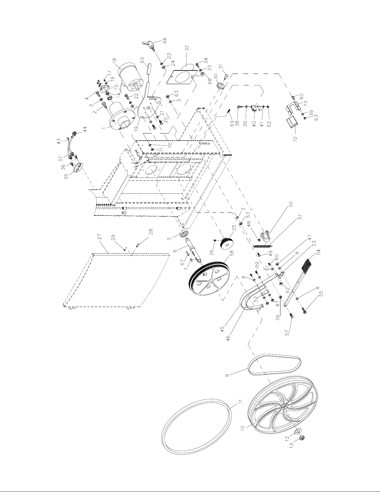
Lower Wheel and Motor Assembly (20QT)
42
Page 43

Blade Guide Assembly (20QT)
Index No. Part No. Description Size Qty
1 ............... TS-0051051 .............Hex Cap Sc re w ..................................................5/16-18x1 ................... 4
2 ............... TS-0720081 .............Lock Washer ......................................................5/16 ............................ 4
3 ............... TS-0680031 .............Flat Washer ........................................................5/16 ............................ 8
4 ............... JWBS20-3 04 ............Guide Bar Bracket ................................................................................. 1
5 ............... JWBS18-305 ...........Worm .................................................................................................... 1
6 ............... JWBS18-3 06 ............E-Ring ................................................................E-8 ............................. 2
7 ............... JWBS18-3 07 ............Gear Base ............................................................................................. 1
8 ............... JWBS18-3 08 ............Bushing ................................................................................................. 1
9 ............... JWBS18-3 09 ............C-Ring ................................................................S-12 ........................... 2
10 ............. JWBS18-310 ............Shaft ..................................................................................................... 1
11 ............. JWBS18-311 ............Gear ...................................................................................................... 1
12 ............. TS-0208071 .............Socket Head Cap Screw .....................................5/16-18x1-1/4 ............. 2
13 ............. JWBS20-313 ............Lock Knob ..........................................................5/16 ............................ 1
14 ............. JWBS20-314 ............Plate ...................................................................................................... 1
15 ............. TS-0051011 .............Hex Cap Screw ..................................................5 /1 6 - 1 8 x1/2 ................ 4
16 ............. JWBS20-316 ............Guide Bar .............................................................................................. 1
17 ............. JWBS20QT-317 .......Pointer................................................................................................... 1
19 ............. TS-0050011 .............Hex Cap Screw ..................................................1 /4 - 2 0 x1/2 .................. 1
20 ............. JWBS20QT-320 .......Blade Guard .......................................................................................... 1
21 ............. TS-0680021 .............Flat Washer ........................................................1/4 .............................. 6
22 ............. TS-0720071 .............Lock Washer ......................................................1/4 .............................. 2
23 ............. TS-0050021 .............Hex Cap Screw ..................................................1 /4 - 2 0 x5/8 .................. 2
24 ............. JWBS20-324 ............Wing Bolt ............................................................................................... 2
25 ............. JWBS18DX-325 .......Bracket Shaft ......................................................................................... 1
26 ............. JWBS20-326 ............C-Ring ................................................................................................. 10
27 ............. BB-6202ZZ ..............Ball Bearing ........................................................6202 ......................... 10
28 ............. JWBS20-328 ............Spac er................................................................................................... 4
29 ............. JWBS20-329 ............Upper Guide Shaft ................................................................................. 2
30 ............. TS-0267041 .............Set Screw ...........................................................1/4-2 0x3/8 .................. 2
31 ............. JWBS20-2 ...............Lock Knob ............................................................................................. 1
32 ............. TS-081F052 .............Pan Head Machine Screw ..................................1/4-20x3/4 .................. 1
33 ............. JWBS18-333 ............Hand Wheel
34 ............. TS-0267041 .............Set Screw ...........................................................1/4-2 0x3/8 .................. 1
35 ............. JWBS20-103A .........Handle................................................................................................... 1
36 ............. JWBS18DX-336 .......Cutting Height Scale .............................................................................. 1
37 ............. JWBS18DX-337 .......Bracket .................................................................................................. 1
38 ............. JWBS18DX-338 .......Base ...................................................................................................... 1
39 ............. JWBS20-339 ............Threaded Lock Bushing ......................................................................... 1
40 ............. JWBS20-340 ............Bolt........................................................................................................ 1
41 ............. JWBS18DX-341 .......Lock Knob ............................................................................................. 1
42 ............. JWBS20-342 ............Screw .................................................................................................... 2
44 ............. JWBS20-344 ............Guide Bar Bracket ................................................................................. 1
45 ............. TS-0270031 .............Set Screw ...........................................................5/16-18x3/8 ................ 2
46 ............. TS-0720111 .............Lock Washer ......................................................1/2 .............................. 1
47 ............. TS-0561051 .............Hex Nut ..............................................................1/2-13 ......................... 1
48 ............. TS-1521011 .............Set Screw ...........................................................M4x4 .......................... 8
49 ............. JWBS20-349 ............Thu mb Screw ........................................................................................ 2
50 ............. TS-0207031 .............Socket Head Cap Screw .....................................1/4-20x5/8 .................. 3
51 ............. TS-0207021 .............Socket Head Cap Screw .....................................1/4-20x1/2 .................. 2
52 ............. JWBS20-352 ............Bracket .................................................................................................. 1
53 ............. JWBS18DXA-353 ....Th umb Screw .....................................................1/4 -20x1/2 .................. 2
54 ............. JWBS20-354 ............Bearing Support .................................................................................... 2
55 ............. JWBS20-355 ............Lock Bushing ......................................................................................... 1
56 ............. TS-0720071 .............Lock Washer ......................................................1/4 .............................. 1
57 ............. TS-0206021 .............Socket Head Cap Screw .....................................#10-24x1/2 ................. 2
58 ............. JWBS18DX-357 .......Bearing Bracket ..................................................................................... 1
59 ............. JWBS18DX-360 .......Shaft ..................................................................................................... 1
.......................................................................................... 1
43
Page 44

Index No. Part No. Description Size Qty
60 ............. JWBS20-360 ............Bracket .................................................................................................. 1
61 ............. JWBS18DX-361 .......Adjusting Screw ..................................................................................... 1
62 ............. JWBS18DX-362 .......Adjusting Bracket................................................................................... 1
63 ............. JWBS18DX-363 .......Nut ........................................................................................................ 1
64 ............. TS-0267021 .............Set Screw ...........................................................1/4-2 0x1/4 .................. 1
65 ............. JWBS18DX-365 .......Set Screw, Special ................................................................................ 1
66 ............. JWBS18DX-366 .......Adjustment Handle ................................................................................ 2
67 ............. TS-0680031 .............Flat Washer ........................................................5/16 ............................ 1
68 ............. JWBS20-329A .........Lower Guide Shaft ................................................................................. 2
69 ............. TS-0561011 .............Hex Nut ..............................................................1/4-20 ......................... 1
70 ............. 6295293...................Locking Handle ...................................................................................... 1
71 ............. JWBS18DX-359 .......Locking Handle ...................................................................................... 1
72 ............. TS-0207041 .............Socket Head Cap Screw .....................................1/4-20x3/4 .................. 2
44
Page 45

Blade Guide Assembly
Upper Bearing Guide
Lower Bearing Guide
45
Page 46

Table and Fence Assembly (20QT)
Index No. Part No. Description Size Qty
1 ............... JWBS18-4 01 ............Locking Handle ...................................................................................... 1
2 ............... TS-0680021 .............Flat Washe r ........................................................1/4 ............................ 11
3 ............... JWBS18-4 03 ............Miter Gauge Body.................................................................................. 1
4 ............... JWBS20-1 56 ............Guide Disc............................................................................................. 1
5 ............... JWBS18-4 05 ............Screw .................................................................M6x8 .......................... 1
6 ............... JWBS18-4 06 ............Pointer ................................................................................................... 1
7 ............... JWBS18-4 07 ............Guide Bar .............................................................................................. 1
8 ............... JWBS18D X-408 .......Trunnion Support Bracket ...................................................................... 1
9 ............... TS-0051071 .............Hex Cap Sc re w ..................................................5/16-18x1-1 /2 ............. 4
10 ............. TS-0720081 .............Lock Washer ......................................................5/16 ............................ 8
11 ............. TS-0270061 .............Set Screw ...........................................................5/16-18x5/8 ................ 2
12 ............. TS-0060111 .............Hex Cap Screw ..................................................3 /8 - 1 6 x2-1 /2 ............... 1
13 ............. TS-0561031 .............Hex Nut ..............................................................3/8-16 ......................... 1
14 ............. TS-0720091 .............Lock Washer ......................................................3/8 .............................. 1
15 ............. JWBS18-415 ............Lock Knob ............................................................................................. 2
16 ............. JWBS18X-416 .........Trunnion ................................................................................................ 2
17 ............. JWBS18-417 ............Trunnion Clamp Shoe ............................................................................ 2
18 ............. TS-1491081 .............Hex Cap Screw ..................................................M 1 0 x50 ...................... 1
19 ............. TS-1503041 .............Socket Head Cap Screw .....................................M6x16 ........................ 6
20 ............. JWBS18-420 ............Scale ..................................................................................................... 1
21 ............. JWBS20-421 ............Table ..................................................................................................... 1
22 ............. JWBS18-422W ........Front Rail .............................................................................................. 1
23 ............. TS-0050021 .............Hex Cap Screw ..................................................1 /4 - 2 0 x5/8 .................. 9
24 ............. TS-0720071 .............Lock Washer ......................................................1/4 ............................ 10
25 ............. JWBS18-425 ............Scale ..................................................................................................... 1
26 ............. JWBS20-426 ............Guide Rail ............................................................................................. 1
27 ............. JWBS18-4 27W ........Rear Rail ............................................................................................... 1
28 ............. JWBS20-144 ............Table In sert ........................................................................................... 1
29 ............. JWBS20-145 ............Roll Pi n...............................................................3x10 ........................... 1
30 ............. JWBS18-430 ............Fence Body ........................................................................................... 1
31 ............. JWBS18-431 ............Handle................................................................................................... 1
32 ............. JWBS18-432
33 ............. JWBS18 -433 W ........Loc k Plate ............................................................................................. 1
34 ............. JWBS18-434 ............Pad ....................................................................................................... 5
35 ............. JWBS18-435 ............Pin......................................................................................................... 1
36 ............. JWBS18-436 ............Pin......................................................................................................... 1
37 ............. JWBS20-437EA .......Fence .................................................................................................... 1
38 ............. TS-0208041 .............Socket Head Cap Screw .....................................5/16-18x3/4 ................ 4
39 ............. TS-0680031 .............Flat Washer ........................................................5/16 ............................ 4
40 ............. TS-0810012 .............Screw .................................................................#10-24x1/4 ................. 2
41 ............. TS-0733031 .............External Tooth Lock Washer ...............................#10 ............................. 1
42 ............. JWBS18-442 ............Pointe r................................................................................................... 1
43 ............. TS-0561011 .............Hex Nut ..............................................................1/4-20 ......................... 2
44 ............. JWBS18-444 ............Sliding P a d ............................................................................................ 1
45 ............. JWBS18-445 ............Rear Hook ............................................................................................. 1
46 ............. JWBS18-446 ............Pointe r................................................................................................... 1
47 ............. JWBS18-447 ............Screw .................................................................M5x8 .......................... 1
48 ............. JWBS18DX-448 .......Table Pin ............................................................................................... 1
49 ............. JWBS18-449E .........Resaw Guide ......................................................................................... 1
50 ............. JWBS20-450 ............Lock Knob ............................................................................................. 1
................. JWBS18-M GCP .......Miter Gauge Assembly .......................................................................... 1
................. JWBS20 QT-FCP ......Fence Assembly .................................................................................... 1
51 ............. JWBS18-451 ............JET Fen ce Label ................................................................................... 1
52 ............. TS-1550041 .............Flat Washer ........................................................M6 .............................. 6
53 ............. TS-1551041 .............Lock Washer ......................................................M6 .............................. 6
54 ............. TS-2210651 .............Hex Cap Screw ..................................................M 1 0 x65 ...................... 1
55 ............. JWBS18DX-455 .......Lower Blade Guard ................................................................................ 1
............Cam ...................................................................................................... 1
46
Page 47

Index No. Part No. Description Size Qty
57 ............. TS-0051091 .............Hex Cap Screw ..................................................5 /1 6 - 1 8 x2 ................... 2
58 ............. 40-0260 ...................Wrench .................................................................................................. 1
59 ............. JWBS18DX-459 .......C-Ring ................................................................S-10 ........................... 1
60 ............. JWBS18DX-460 .......Link Chain ............................................................................................. 1
61 ............. TS-0680031 .............Flat Washer ........................................................5/16 ............................ 6
62 ............. 2013-285 .................End Cover ............................................................................................. 2
63 ............. JWBS20QT-463 .......Lock Handle .......................................................................................... 1
47
Page 48

Electrical Connections
1 3/4 HP, 1Ph, 115V
Band Saw Model No.: JWBS-18QT-1 (SN 710750B)
3HP, 1 Phase
1-3/4 HP, 1Ph, 230V
Band Saw Model No.: JWBS-18QT-1 (SN 710750B)
48
Page 49

3 HP, 1Ph, 230V
Band Saw Model No.: JWBS-18QT-3 (SN 710751B)
Magnetic Switch
Electrical Board
GREEN
BLACK
RED
WHITE
YELLOW
LED
R
C
Motor
WHITE
BLACK
GROUND
YELLOW
GREEN
959698 97
RED
300MFD
125VAC
60uF
250WVAC
GREEN
A1
1L2
2T1
2T1
WHITE
BLACK
5L3
3L2
13NO
4T2
6T3
14NO
A2
4T2
6T3
BLACK
WHITE
WHIET
BLACK
GREEN
GREEN
WHITE
BLACK
49
Page 50

3 HP, 1Ph, 230V
Band Saw Model No.: JWBS-20QT-3 (SN 708754B)
Magnet ic Switch
Electri cal Boa r d
GREEN
GREEN
BLACK
RED
WHITE
YELLOW
LED
R
C
Motor
WHITE
BLACK
GROUND
YELLOW
GREEN
9596
GREEN
RED
300MFD
125VAC
60uF
250WVAC
A1
1L2
2T1
2T1
WHITE
BLACK
5L3
3L2
13NO
4T2
6T3
14NO
A2
4T2
6T3
98 97
BLACK
WHITE
WHIET
BLACK
GREEN
WHITE
BLACK
50
Page 51

5 HP, 1Ph, 230V
Band Saw Model No.: JWBS-20QT-5 (SN 708755B)
Magnetic Switch
Electrical Board
GREEN
BLACK
RED
WHITE
YELLOW
LED
CR
Motor
WHITE
BLACK
GROUND
YELLOW
GREEN
95
GREEN
RED
300MFD
250VAC
50uF
450WVAC
A1
3L2
1L2
2T1 4T2 6T3
4T2
2T1
WHITE
BLACK
5L3
6T3
BLACK
13NO
14NO
A2
9698 97
WHITE
WHIET
BLACK
GREEN
GREEN
WHITE
BLACK
51
Page 52

427 New Sanford Road
LaVergne, TN 37086-4184, USA
Phone: 800-274-6848
www.jettools.com
52
 Loading...