

Page 1

This Manual is Bookmarked
Operating Instructions and Parts Manual
14-inch Woodworking Band Saw
Models: JWBS-14OS, JWBS-14CS
WMH TOOL GROUP
2420 Vantage Drive
Elgin, Illinois 60123 Part No. M-708115
Ph.: 800-274-6848 Revision C 9/05
www.wmhtoolgroup.com Copyright © WMH Tool Group
Page 2

This manual has been pre pared f or the owner and op erators of a JET JWBS-14 Band S aw. Its purpose,
aside from machine operation, is to promote safety using accepted operating and maintenance
procedures. To obtain maximum life and efficiency from your band saw and to aid in using it safely,
please read this manual thoroughly and follow the i nstruct ions carefully.
Warranty and Service
WMH Tool Gr oup warrants ever y product it sell s. If one of our tools needs s ervice or repai r, one of our
Authorized Service Centers located throughout the United States can provide quick service or
information.
In most cases, a W MH Tool Group Servi ce Center can assist i n authori zing repai r work, obtai ning part s,
or perform routine or major maintenance repair on your JET product.
For the name of an Aut horized Service Cent er in your area, pl ease call 1-800-274-6848, or vi sit our web
site at www.wmhtoolgroup.com
More Information
Remember, WMH Tool Group i s consistently adding new products to the li ne. For complete, up-to-dat e
product information, check with your local WMH Tool Group distributor, or visit our web site at
www.wmhtoolgroup.com
WMH Tool Group Warranty
WMH Tool Group makes every effort to assure that it s products meet high quali ty and durability standards
and warrants to the original retail consumer/purchaser of our products that each product be free from
defects in mat erials and workmanship as foll ows: 1 YEA R LIMITED WARRANTY ON ALL PRODUCTS
UNLESS SPECIFIED OTHERWISE. This Warranty does not apply to defects due directly or i ndirectly to
misuse, abuse, negl igence or acc idents, norm al wear-and-tear , repair or alterati ons outside our f aciliti es,
or to a lack of maintenanc e.
WMH TOOL GROUP LIMITS ALL IMPLIED WARRANTIES TO THE PERIOD SPECIFIED ABOVE,
BEGINNING FROM THE DATE THE PRODUCT WAS PURCHASED AT RETAIL. EXCEPT AS STATED
HEREIN, ANY IMPLIED WARRANTIES OR MERCHANTABILITY AND FITNESS ARE EXCLUDED.
SOME STATES DO NOT ALLOW LIMITATIONS ON HOW LONG THE IMPLIED WARRANTY LASTS,
SO THE ABOVE LIMITATION MAY NOT APPLY TO YOU. IN NO EVENT SHALL WMH TOOL GROUP
BE LIABLE FOR DEATH, INJURIES TO PERSONS OR PROPERTY, OR FOR INCIDENTAL,
CONTINGENT, SPECIAL, OR CONSEQUENTIAL DAMAGES ARISING FROM THE USE OF OUR
PRODUCTS. SOME STATES DO NOT ALLOW THE EXCLUSION OR LIMITATION OF INCIDENTAL
OR CONSEQUENTIAL DAMAGES, SO THE ABOVE LIMITATION OR EXCLUSION MAY NOT APPLY
TO YOU.
To take advantage of this warranty, the product or part must be returned for examination, postage
prepaid, to an Authorized Service Center designated by our office. Proof of purchase date and an
explanati on of the complaint m ust accompany the merchandi se. If our inspecti on discloses a defec t, we
will either repair or replace the product at our discret i on, or ref und the purc hase price if we cannot readi l y
and quickly provide a repai r or replac ement. We will return the repai red product or replacem ent at WMH
Tool Group’s ex pense, but if it is determ ined there i s no defect, or that the def ect resulted f rom causes
not within the scope of WMH Tool Group’s warranty, then the user must bear the cost of storing and
returning t he product . This warranty gives you specif ic legal ri ghts; you m ay also hav e other ri ghts, whic h
vary from state t o state.
WMH Tool Group sells through distribut ors only. Members of the WMH Tool Group reserve the right to
effect at any time, wit hout prior notice, alter ations to parts, fittings and accessory equi pment, which they
may deem necessary for any reason whatsoever.
2
Page 3

Table of Contents
Warranty and Servic e ..............................................................................................................................2
Warning...................................................................................................................................................4
Introduction.............................................................................................................................................. 6
Specifications..........................................................................................................................................6
Unpacking – JWBS-14OS........................................................................................................................7
Contents of the Shipping Container......................................................................................................7
Fasteners.............................................................................................................................................7
Unpacking – JWBS-14CS........................................................................................................................8
Contents of the Shipping Container......................................................................................................8
Fasteners.............................................................................................................................................8
Assembly of JWBS-14OS........................................................................................................................9
Assembly of JWBS-14CS ......................................................................................................................12
Grounding Instructions...........................................................................................................................14
115 Volt Operati on .............................................................................................................................15
230 Volt Conversion...........................................................................................................................15
Extension Cords................................................................................................................ .................16
Adjustments........................................................................................................................................... 16
Tilting th e Table..................................................................................................................................16
Adjusting 90° Table Stop....................................................................................................................16
Changing Blades................................................................................................................................17
Adjusting Bl ade Tension.....................................................................................................................17
Adjusting Bl ade Trac ki ng.................................................................................................................... 18
Adjusting Upper Blade Guide Assembly..............................................................................................18
Adjusting Bl ade Guide and Blade Support Bearing .............................................................................19
Troubleshooting JWBS-14CS/OS Band Saw ..........................................................................................21
Optional Accessories .............................................................................................................................22
Accessory Blades...............................................................................................................................22
Replacement Parts................................................................................................................................23
Body Assembly (JW BS-14CS /O S Band Saw).....................................................................................24
Body Assembly (JW BS-14CS /O S Band Saw).....................................................................................25
Body Assembly (JW BS-14CS /O S Band Saw).....................................................................................26
Closed Stand Assembl y ( JWBS-14CS B and S aw)..............................................................................27
Closed Stand Assembl y ( JWBS14-CS B and S aw)..............................................................................28
Open Stand Assembly (JWBS-14OS Band Saw)................................................................................29
Open Stand Assembly (JWBS-14OS Band Saw)................................................................................30
Electrical Connections – 115 volt (JWBS-14CS/ OS B and Saw)..............................................................31
Electrical Connections – 230 volt (JWBS-14CS/ OS B and Saw)..............................................................32
3
Page 4

Warning
1. Read and understand the entire owners manual bef or e attempti ng assem bly or operation.
2. Read and understand the warnings po sted on the m achine and i n thi s manual. Failur e to comply wit h
all of these warnings m ay cause seriou s i njury.
3. Replace the warning labels if they become obscured or removed.
4. This band saw is designed and i ntended for use by proper ly tr ained and ex peri enced personnel onl y.
If you are not familiar with the proper and safe operation of a band saw, do not use until proper
training and knowledge have been obtained.
5. Do not use this band saw for other than its intended use. If used for other purposes, WMH Tool
Group discl aims any real or implied warranty and holds itself harmless from any injury t hat may result
from that use.
6. Always wear approv ed safety glasses/face shields whil e using this band saw. Everyday eyegl asses
only have impact resi stant lenses; they are not safety glasses.
7. Before operating this band saw, remove tie, rings, watches and other j ewelry, and roll sleeves up past
the elbows. Remove all loose clothi ng and c onfine long hair. Non-slip footwear or ant i-skid floor strips
are recommended. Do not wear gloves.
8. Wear ear protector s (plugs or muffs) during ext ended peri ods of oper ation.
9. Some dust created by power sanding, sawing, grinding, drilling and other construction activities
contain chemi cals known to cause cancer , bir th defects or other r eproductiv e harm . Some examples
of these chemic als are:
• Lead from lead based paint.
• Crystalli ne sil ic a from bricks, cement and other m asonry pr oducts.
• Arsenic and chromium from chemically treated lumber.
Your risk of exposure varies, depending on how often you do this type of work. To reduce your
exposure to these chemicals, work in a well-ventilated area and work with approved safety
equipment, such as face or dust masks that are specifically designed to filter out microscopic
particles.
10. Do not operate this machine while tired or under the influence of drugs, alcohol or any medicati on.
11. M ak e c er tain the switch is in the OFF position before connecti ng the machine to the power supply.
12. M ak e c ertain the machine is properly grounded.
13. M ak e all machine adjustm ents or maintenance with the machine unplugged from the power source.
14. Remove adjusting keys and wrenches. Form a habit of checking to see that keys and adjusting
wrenches are removed from the machine before turning it on.
15. Keep safety guards in place at all times when the machi ne is in use. If removed for maintenance
purposes, use extreme caution and replace the guards immediately.
16. M ak e sure the band saw is firmly secured to t he floor or bench before use.
17. Check damaged parts. Before further use of the machine, a guard or other part that is damaged
should be carefully checked to determine that it will operate properly and perform its intended
function. Check for alignment of moving part s, binding of moving parts, br eakage of parts, mounting
and any other condi ti ons that m ay affect its operati on. A guard or ot her part that i s damaged shoul d
be properly repaired or replaced.
18. P r ov ide for adequate space surrounding work area and non-glare, overhead lighting.
19. K eep the floor around the m achi ne cl ean and free of scrap material, oil and grease.
20. K eep v isitors a safe distanc e from the work area. Keep children away.
4
Page 5

blahblahblah
21. M ak e y our workshop child proof with padlocks, master switches or by removing starter keys.
22. Giv e your work undivi ded attention. Looking ar ound, carryi ng on a conversation and “ horse-play” ar e
careless acts that can r esul t in serious injury.
23. Maintain a balanced stance at all times so that you do not fall or lean against the blade or other
moving part s. Do not over r eac h or use exc essive force to perform any machine operation.
24. Use the ri ght t ool at the cor rect speed and feed r ate. Do not forc e a tool or attachment to do a job for
which it was not designed. T he ri ght tool will do the job better and safer.
25. Use recom mended accessories; i mproper accessories may be hazardous.
26. Maintain t ools with care. Keep blade sharp and cl ean for the best and safest per formance. Follow
instructions for lubricating and changing accessories.
27. M ake sure the work piece i s held firml y against the rip f ence or miter gauge as it is fed through the
blade.
28. Turn off the mac hine before cleaning. Use a brush or compressed air to remove chips or debri s — do
not use your hands.
29. Do not stand on the machine. Seri ous injury could occur if the machine ti ps over.
30. Never leave the mac hine running unattended. Turn the power off and do not leave the machine until it
comes to a complete stop.
31. Remove loose item s and unnecessary work pieces from the area before starting the machine.
Familiarize you rself with the following safety no ti ces used in this manual:
This means that if precautions are not heeded, it may result i n mi nor injury and/or
possible machine damage.
This means that if precautions are not heeded, it may result i n serious injury or possibly
even death.
- - SAVE THESE INSTRUCTIONS - -
5
Page 6

Introduction
This manual i s provided by JET covering the safe operat ion and maintenance procedures f or a Model
JWBS-14 Band Saw. This manual contains instructions on installation, safety precautions, general
operating proc edures, maintenance i nstructions and part s breakdown. This mac hine has been designed
and constructed to pr ovi de years of troubl e free operation if used in accor dance with instr ucti ons set forth
in this manual . If ther e are any que sti ons or com m ents, please cont act ei t her your loc al suppl ier or W MH
Tool Group. WMH Tool Group can also be reached at our web site: www.wmhtoolgroup.com.
Specifications
Model Number:........................................................JWBS-14OS..........................................JWBS-14CS
Stock Number..................................................................708113................................................708115K
Cutting Capacity (height/in.)...................................................... 6............................................................6
Cutting Capacity (width/in.) ............................................... 13-1/2....................................................13-1/2
Minimum Blade Width (in.)..................................................... 1/8.........................................................1/8
Maximum Blade Width (in.).................................................... 3/4.........................................................3/4
Blade Length (in.) ............................................................. 93-1/2....................................................93-1/2
Blade Speed (SFPM )...........................................................3000......................................................3000
Table Size (in.) ................................................................15 x 15.................................................. 15 x 15
Table Slot Size (DxW/in.)...............................................3/8 x 3/4................................................ 3/8 x 3/4
Table He igh t Fr om Floor (in .).................................................. 44....................................................43-1/2
Table Tilt (deg.) ................................................... 45 right, 10 left.......................................45 right, 10 left
Dust Port Diameter (in.)............................................................ 4............................................................4
Overall Dimensions (HxWxD/in.).............................. 68 x 34 x 20........................................... 68 x 26 x 19
Motor................................ 3/4HP, 1Ph, 115/230V (prewired 115).......1HP, 1Ph, 115/230V (prewired 115)
Net Weigh t (lb s.)................................................................... 172........................................................185
Shipping Weigh t (lbs.)........................................................... 183........................................................197
The above specifications were current at the tim e this manual was publi shed, but because of our policy of
continuous im provement, WHM Tool Group reserv es the right to change specif ications at any tim e and
without pri or notic e, without incurring obligations.
6
Page 7
Unpacking – JWBS-14OS
Open shipping container and check for shipping damage. Report any damage immediately to your
distribut or and shipping agent. Read the instructi on manual thoroughly for assembly, m aintenance and
safety instructions.
Contents of the Shipping Contai ner
1 Stand top with motor support plate
4 Stand legs
2 Cross braces-short
2 Cross braces-long
1 Stand support plate
1 Saw body
1 Table
1 Motor
Fasteners
1 V-belt
1 Pulley cover
2 Table lock knobs
1 Table pin
1 Trunnion support br ac k et
1 Fastener package (see below)
1 Instruction Manual
1 Warranty Card
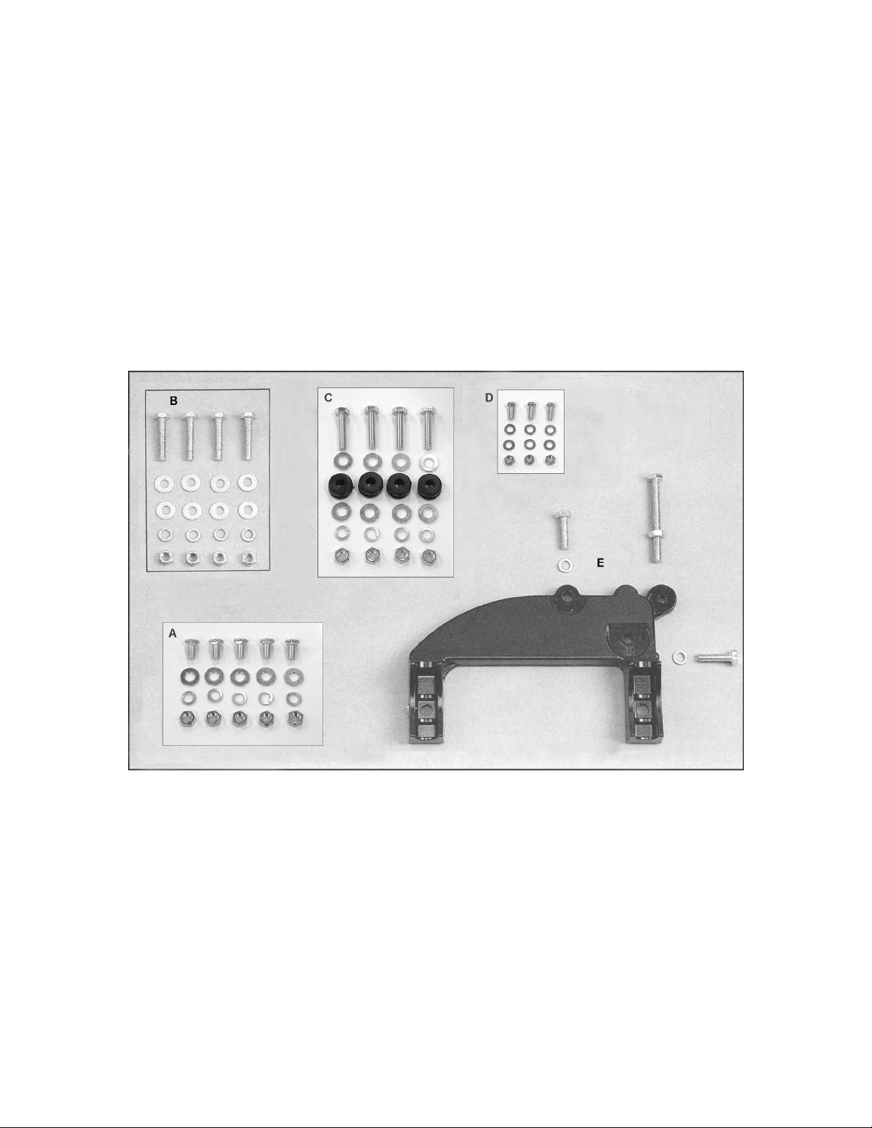
A. Stand Assembly (parti al quantity shown)
40 – M8x16 carriage bol ts
40 – M8 flat washers
40 – M8 lock washers
40 – M8 hex nuts
B. Saw Body to Stand
4 – M8x40 hex cap screws (approx. 1- 1/2")
8 – M8 flat washers
4 – M8 lock washers
4 – M8 hex nuts
C. Motor to Stand
4 – M8x35 hex cap screws (approx. 1- 3/8”)
8 – M8 flat washers
4 – rubber grommets
4 – M8 lock washers
4 – M8 hex nuts
D. Pulley Cover to Stand
3 – M5x12 pan head screws (approx. 1/2”)
6 – M5 fl at washers
3 – M5 hex nuts
E. Trunnion Support Bracket to Saw Bod y
2 – M8x30 hex cap screws (approx. 1- 1/4")
2 – M8 lock washers
1 – M8x80 hex cap screw (for table stop -
approx. 3-1/8” long)
1 – M8 hex nut (for table stop)
7
Page 8
Unpacking – JWBS-14CS
Open both shipping c ontainer s and check for shippi ng damage. Report any damage im mediately to y our
distribut or and shipping agent. Read the instructi on manual thoroughly for assembly, m aintenance and
safety instructions.
Contents of the Shipping Contai ner
Container One:
1 Closed stand with motor
1 Pulley cover
1 V-belt
Container Two:
1 Saw body
1 Table
Fasteners
2 Table lock knobs
1 Table pin
1 Trunnion support br ac k et
1 Fastener package (see below)
1 Instruction Manual
1 Warranty Card
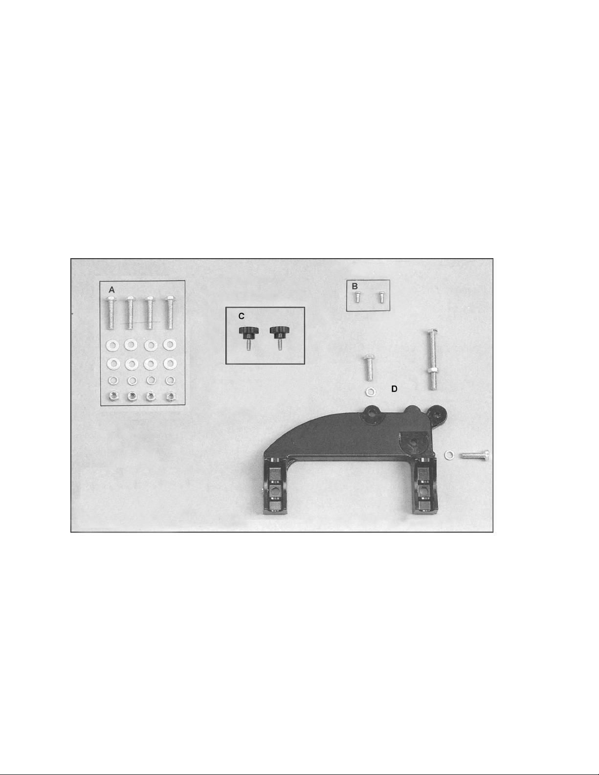
A. Saw Body to Stand
4 – M8x40 hex cap screws
(approx. 1-1/ 2" long)
8 – M8 flat washers
4 – M8 lock washers
4 – M8 hex nuts
B. Strain Relief Plate to Stand
2 – M5x12 pan head machine screws
C. Pulley Cover to Base
2 – Knobs
D. Trunnion Support Bracket t o Saw Body
2 – M8x30 hex cap screws
(approx. 1-1/ 4" long)
2 – M8 lock washers
1 – M8x80 hex cap screw (for table stop -
approx. 3-1/8” long)
1 – M8 hex nut (for table stop)
8
Page 9
Assembly of JWBS-14OS
NOTE: If any of the assembl y procedures need
further cl arification, refer t o the exploded views
in the back of this manual.
Tools Required for Assembl y
Metric combination wrench set and adjustable
wrench
#1 and #2 cross point screwdrivers
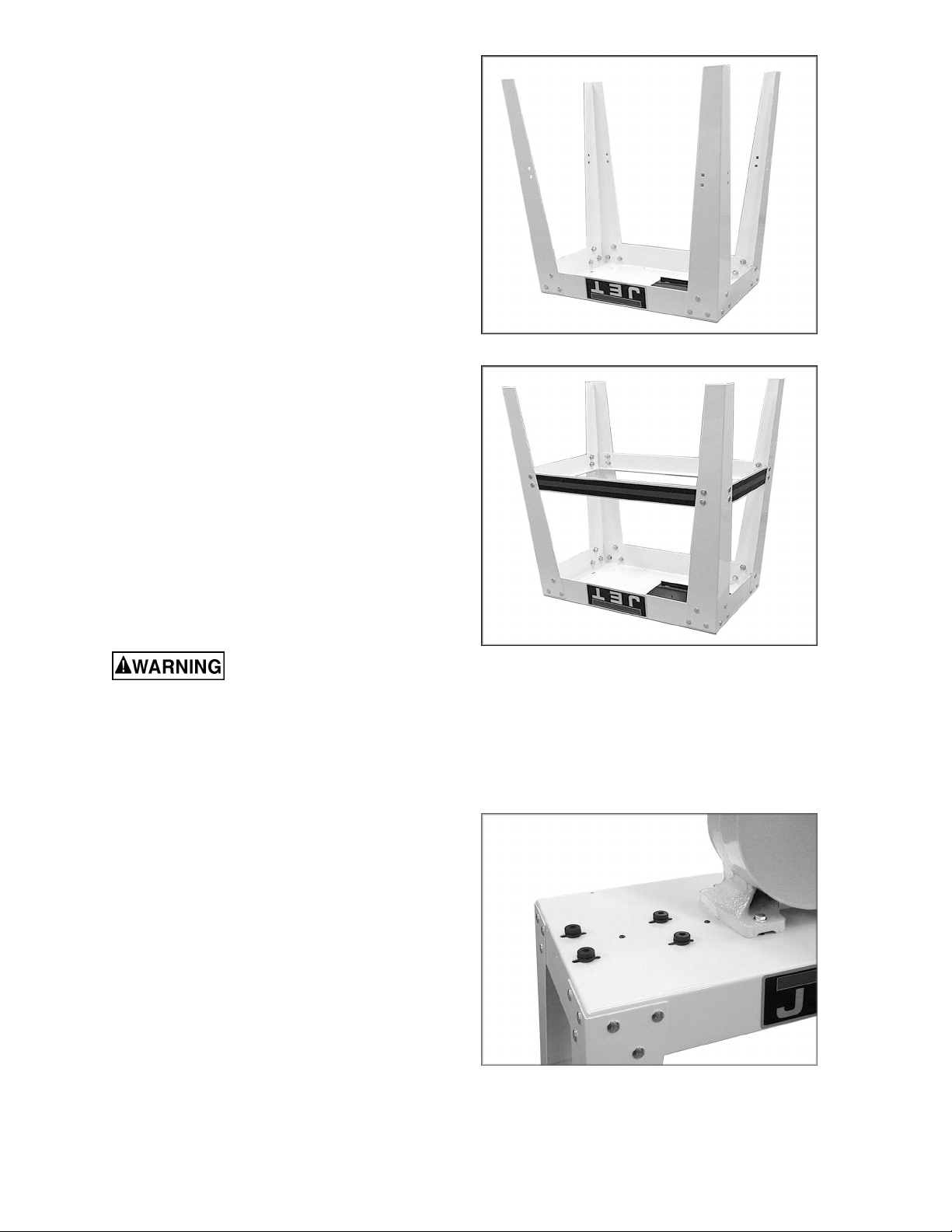
1. Place stand top upside down on a level
surface. Fasten f our stand legs to stand top
using carriage bol t s, washers, l ock washers,
and nuts, as shown in item A on page 7.
Note: Stand legs f asten to outside of stand
top (Figure 1). Do not tight en at this time.
2. Fasten two long braces and two short
braces to stand legs using carriage bolts,
washers, lock washer s, and nuts, as sho wn
in item A, page 7. Do not tighten at this time.
See Figure 2.
3. Tur n assembly ov er and stand it on it s legs.
Push down slight ly on the top t o make sure
the stand settles properly and all four legs
sit flat on a level surface. Tighten all nuts.
Saw body is heavy! Use
caution when lif ting and stabilize unti l firmly
attached to th e stand! F ailu re to comply may
cause serious injury!
4. With the aid of a second p erson, l ift the saw
body out of the shipping cont ainer and place
onto the stand top. Be sure front of saw
(with JET logo) faces stand f ront (JET l ogo).
See photo on cover for orientation.
Figure 1
Figure 2
5. Line up holes in saw body with holes in
stand. Place support plate to the underside
of stand as shown in the parts diagram for
the open stand assembl y (item 5, page 30).
Fasten saw body, stand, and support plate
together with f our hex cap screws, eight flat
washers, four lock washers, and four hex
nuts, as shown in item B on page 7.
6. To mount the motor, place four rubber
grommets over holes in stand top (Figur e 3) .
Note: Use of rubber grommets is essential
for eliminati ng excessive vibrati on.
Figure 3
9
Page 10
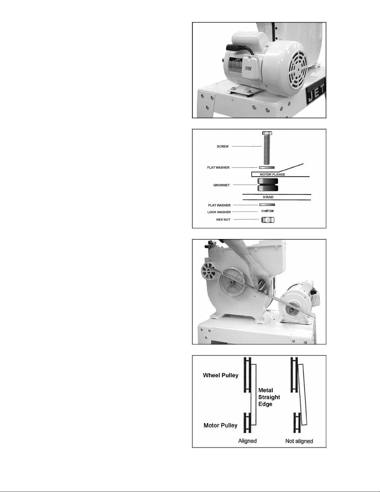
7. Place motor over rubber grommets and
fasten to stand top with four hex cap
screws, eight flat washers, four lock
washers, and four hex nuts, as shown in
item C, page 7. See Figure 4. The
arrangement of these fasteners is shown in
Figure 5. Do not tight en at t his tim e.
8. Align the motor pulley with the large pulley
using a straight edge against the flat sides
of the pulleys, as shown in Figure 6. The
pulleys should li e in a straight plane (Figure
7). Slide the motor as needed to align the
pulleys. If further adjustment is required,
loosen the set screw in one or m ore of the
pulleys and move the pulley(s) until t hey line
up. Tighten set screw(s).
IMPORTANT: W hen movi ng the pull eys, do
not position them beyond the end of the
shaft. Both pulleys must fully engage the
shaft and the key.
Figure 4
Figure 5
Figure 6
Figure 7
10
Page 11

9. Place v-belt over both pulleys. See Figure 8.
10. Tension v -belt by moving m otor away from
the saw body and tighten the motor mount
nuts. (Do not over-tighten motor mount
bolts. Tighten just enough to tension belt.)
Belt is properly tensioned when finger
pressure bet ween the two pull eys (Fi gure 8)
causes approximately 1/2” deflecti on.
11. Place pulley cover over both pulleys and
fasten to stand using three pan head
screws, six washers, and three hex nut s, as
shown in item D, page 7. See Figure 9.
12. Att ach t runnion support br acket to saw body
with two hex cap screws and two lock
washers as shown in item E, page 7. See
Figure 10.
13. Thread nut onto table stop bolt (Figure 10)
and attach to trunnion support bracket.
Figure 8
14. To mount table, remove table insert and
table pin ( see F igure 11). Or ient the table so
that the saw blade will pass through t he slot
in the table and into the center opening.
Continue holdi ng up the table, and turn the
table so the two screws that are hanging
verticall y from below the table will slide into
the holes on the trunnion support bracket.
Lower the table. The screws should now
protrude below the t runnion support bracket
- attach lock knobs to the ends of these
screws. See Figure 11.
15. Re- install table insert and table pin.
16. J oin motor plug to switch plug.
17. Transportation and handling may have
caused some fasteners to loosen. Before
operating, c heck all screws, bolts, and n uts
to make sure they are snug. Operate
machine only after reading the entire
manual including blade tracking, blade
guide adjustments, and safety rules.
18. Ex posed metal surfaces, such a s the table,
have been giv en a protective coating. This
should be cleaned with a soft cloth and
solvent, such as kerosene. Do not use
acetone, gasoline, or lacquer thinner. Do not
use an abrasive pad, and do not get
solvents on plasti c par ts.
Figure 9
Figure 10
Proceed to “Grounding Instructions” on page 14.
Figure 11
11
Page 12

Assembly of JWBS-14CS
Tools Required for Assembl y
Metric combination wrench set and
adjustable wrench
#1 and #2 cross point screwdrivers
Exposed metal surfaces, such as the table, hav e
been given a prot ective c oating. This should be
cleaned with a soft cloth and solvent, such as
kerosene. Do not use an abra siv e pad, and do
not get solvents on pl ast ic par ts.
1. Remove pulley cov er from i nsi de of stand.
2. Place cabinet stand upright on a level
surface. If desired, the stand can be further
stabilized by securing it t o the floor wit h lag
screws through the inside corner holes. If
using a mobile base, loc k the casters bef ore
assembling or oper ating the band saw.
Saw body is heavy! Use
caution when lif ting and stabilize unti l firmly
attached to th e stand! F ailu re to comply may
cause serious injury!
3. With the aid of a second p erson, l ift the saw
body out of the shipping cont ainer and place
onto stand top. Be sure front of saw (with
JET logo) faces stand f r ont (J ET logo) .
4. Line up hol es in saw body with hol es in top
of stand. Fasten saw body to the stand wit h
four M8 x 40 hex cap screws, eight M8
washers, four M8 lock washers, and four
M8 hex nuts (as shown in item A, page 8).
5. Push motor cord and strain relief plate
through the opening i n the side of the stand
(Fig. 12). Fasten t he strai n rel ief pl ate t o the
stand with two M5 x 12 pan head machine
screws (shown in it em B, page 8).
6. Check the alignment of the pulleys by
placing a str aight edge agai nst the f l at sides
of the motor and wheel pulleys (Figure 13).
If the pulleys lie in a straight plane (Figure
14) they are al igned. If they do not lie in a
straight pl ane, loosen the set screw on one
of the pulleys and shift the pulley in or out
until both pulleys lie in a straight plane.
Tighten set screw.
Figure 12
Figure 13
Figure 14
12
Page 13

IMPORTANT: W hen movi ng the pull eys, do
not position them beyond the end of the
shaft. Both pulleys must fully engage the
shaft and the key.
7. Open the lower door, and place the v-belt
around the motor pulley and the wheel
pulley (see Fi gur e 13).
8. Loosen t he nuts on the four motor mounting
bolts (Figure 15) and tension the v -belt by
pushing down on the motor. Tighten the four
motor mounting nuts.
9. The v -belt i s properly tensioned when f inger
pressure between the two pulleys causes
approxim ately 1/2" deflection (Figur e 16).
10. Screw the two small knobs (Figure 17) into
the threaded holes in the saw body. Slide
the pulley cover down over the knobs, and
tighten the knobs.
11. Att ach t runnion support br acket to saw body
with two M8 x 30 hex cap screws and two
M8 lock washers, a s shown in i tem D, page
8. See Figure 18.
12. Thread nut onto table stop bolt (Figure 18)
and attach to trunnion support bracket as
shown.
Figure 15
Figure 16
Figure 17
Figure 18
13
Page 14

13. To mount the table, remove pin and insert
from the tabl e (Figur e 19) .
14. Orient t he table so the saw blade will pass
through the slot in the table and into the
center opening. Continue holding up the
table, and rotate the table so the t wo scr ews
that are hanging vertically from below the
table will sli de into the holes on the trunni on
support bracket. Lower the table. The
screws should now protrude below the
trunnion support br acket - at tach lock knobs
to the ends of these screws. (Figure 19).
15. Re- install table insert and table pin.
16. Connect the plugs of the motor cord and
switch cord (Figure 20).
17. Transportation and handling may have
caused some fasteners to loosen. Before
operating, c heck all screws, bolts, and n uts
to make sure they are snug. Operate
machine only after reading the entire
manual including blade tracking, blade
guide adjustments, and safety rules.
Grounding Instructions
This band saw must be
grounded while in use to protect the
operator from electric shock.
In the event of a malfunction or breakdown,
grounding provi des a path of least r esistance f or
electric current to reduce the risk of electric
shock. This tool is equipped with an electric cord
having an equipment-grounding conduc tor and a
grounding plug t hat looks similiar to the plug in
Figure 21. The plug must be inserted into a
matching outlet that is properly installed and
grounded in accordanc e wit h al l loc al codes and
ordinances.
Figure 19
Figure 20
Do not modify the plug pr ovided. If it will not fit
the outlet, hav e the proper outlet installed by a
qualified elec trician.
Improper connection of the equipmentgrounding conductor can result in a risk of
electric shock. The conductor, with insulation
having an outer surface that is green with or
without yellow stripes, is the equipmentgrounding conductor. If repair or replacement of
the electric cord or plug is necessary, do not
connect the equi pment-grounding c onduc tor to a
live terminal.
Figure 21
14
Page 15

Check with a qualified electrician or service
o
personnel if the grounding instructions are not
completely understood, or if in doubt as to
whether the tool is properly grounded.
Repair or replace a damaged or worn cord
immediately.
115 Volt Operation
As received from the factory, your bandsaw is
ready to run at 115 volt operation. This
bandsaw, when wired for 115 volt s, is intended
for use on a ci r cuit t hat has an outl et and a pl ug
that looks li ke the one ill ustrated in Fi gure 21. A
temporary adapt er , like the adapt er in Figure 22,
may be used to connect t his plug to a two-pole
receptacle, as shown in Figure 22, if a properly
grounded outlet i s not available. The t emporary
adapter should only be used until a properly
grounded outlet can be installed by a qualified
electrician. This adapter is not applicable in
Canada. The green colored rigid ear, lug, or
tab, extending from the adapter, must be
connected to a permanent ground such as a
properly grounded outlet box, as shown in
Figure 22.
Figure 22
230 Volt Conversion
If 230V, single-phase operation is desired, the
following inst r uc tions must be followed:
1. Disconnect machine from power source.
2. This band saw is supplied with four motor
leads that are connected for 115V
peration, as shown in Figure 23.
Reconnect these f our motor leads for 230V
operation, as shown in Figure 23.
3. The 115V attachm ent pl ug suppli ed with t he
band saw must be repl aced with a UL/CSA
listed plug suitable for 230V operation, as
shown in Figure 24. Contact your local
authorized W MH Tool Group service center
or qualifi ed el ectrician f or proper pr ocedures
to install the plug. The band saw must
comply with all local and national codes
after the 230 volt plug is installed.
4. The band saw with a 230 volt plug should
only be connected to an outlet having the
same configur ation (Figur e 24). No adapter
is availabl e or should be used with t he 230
volt plug.
Figure 23
Important: In all cases (115 or 230 volts),
make certain the receptacle in question is
properly grou nded. I f you are n ot su re, have
a registered el ectrician check the receptacle.
Figure 24
15
Page 16

Extens ion Cords
Use only three wire extension cords that have
three-prong grounding plugs and three-pole
receptacles that accept the tool’s plug.
Make sure the cord is in good condition, and
heavy enough to carry the current your band
saw will draw. An undersized cord will cause a
drop in line voltage, resulting in loss of power
and overheating. Figure 25 shows the correct
size to use depending on cord length and the
ampere rating on your machine’s nameplate. If
in doubt, use the next heavier gauge. The
smaller the gauge number, the heavier the cord.
Repair or replace a damaged or worn cord
immediately.
Adjustments
Unplug the machine from the
power source before making any repairs or
adjustments. Failure to comply may cause
serious injury.
Minimum Gauge Extension Cord
Amp
rating
0-6 120
6-10 120
10-12 120
12-16 120
Line
voltage
Total length of
cord in feet
0 to 25 18
25 to 50 16
50 to 100 16
over 100 14
0 to 25 18
25 to 50 16
50 to 100 14
over 100 12
0 to 25 16
25 to 50 16
50 to 100 14
over 100 12
0 to 25 14
25 to 50 12
over 50
Figure 25
Cord gauge
(AWG)
not recommended
Tilting the Table
1. Loosen two lock knobs (Figure 26).
2. Tilt table up to 45 degrees to the right or
up to 10 degree s to the l ef t. The angl e can
be read on the scale mounted to the
trunnion.
3. Tighten two lock knobs (Figure 26).
Note: Table stop must be removed to tilt tabl e to
the left.
Adjusting 90°°°° Tabl e Stop
1. Disconnect machine from power source.
2. Loosen lock knobs (Figure 26) and tilt
table left until it rests against the table
stop.
3. Use a square placed on the table and
against the blade ( Figure 27) to see if the
table is 90 degrees to the blade.
4. If an adjustm ent is necessary, l oosen lock
knobs, tilt table to the right, and lock in
place.
Figure 26
Figure 27
16
Page 17

5. Loosen j am nut and tur n table stop (Figure
2
b
6) left or right t o raise or lower the stop.
Tighten jam nut to hold table stop in place.
6. Unlock table, tilt back onto table rest and
confirm table is 90 degrees with the blade.
7. If necessary, adj ust scale pointer to zero.
Changing Blades
Blade teeth are sharp! Use
care when hand lin g the saw bl ade. Fail ure t o
comply may cause serious inj ury.
1. Disconnect machine from power source.
2. Loosen blade tension by turning the
tension knob counter c lockwise (Figure 28).
3. Remove the table insert and the table pin.
4. Open both wheel covers.
5. Remove the blade from between upper
and lower blade guides. Remove blade
from upper and lower wheels. Turn blade
to direct through slot in table.
6. Guide new blade thr ough table slot . Place
lade in upper and lower blade guides.
Note: The blade teeth should face the
operator, and they should point down
toward the table.
7. Pl ace bl ade i n the mi ddle of t he upper and
lo wer whee l.
8. Re-install table insert and table pin.
9. Tension and track blade before operating
saw. Fi nd instructions for tensioning and
tracking the blade under "Adjusting Blade
Tension" and "Adjusting Blade Tracking" .
Adjusting Blade Tension
1. Disconnect machine from power source.
2. Turn blade tension knob (Figure 28)
clockwise to t ension blade. A gauge on the
upper wheel slide bracket indicates the
approximate tension according to the width
of the blade. Initially, set the blade tension
to correspond to the bl ade width as marked
on the gauge.
Figure 28
17
Page 18

3. As you become m ore experienced with the
saw, you may find it necessary to change
the blade tension from the initial setting.
Changes in blade width and the type of
material being cut will have an effect on
blade tension.
4. Keep in mind that too little or too much
blade tension can c ause bl ade br eak age.
Adjusting Blade Tracking
Disconnect mach ine from the
power source. Never adjust blade tracking
with the machine runnin g. Failure to comply
may cause serious injury.
“Tracking” refers to how the blade is situated
upon the wheels while in motion. The blade
should track in t he c enter of bot h wheels.
1. The blade must be properly tensioned
before adjusting blade tracking. Make sure
blade guides and blade bearings do not
interfere with the blade.
2. Open the top wheel cover . Rotate the wheel
forward by hand, and observe the position
of the blade on the wheel - it should be in
the center of the wheel.
3. If adjustment is necessary, l oosen wing nut
(Figure 29), and tighten tracking knob
slightly to move blade toward rear of
machine. Slightly loosening the tracking
knob will cause the blade to track toward the
front of the machi ne.
4. After blade is tracking in the center of the
wheel, tighten the wing nut.
Figure 29
Adjusting Upper Blade Guide Assembly
1. Disconnect machine from power source.
2. Loosen lock knob (A, Figure 30) and raise
or lower upper blade guide assembly (B,
Figure 30) t o just abov e the material being
cut.
Figure 29
18
Page 19

3. Tighten lock knob. Make sure blade gui de
blocks (C, Figure 30) are still flat to the
blade. If adjustment is necessary, loosen
lock knob (A, Figure 30) and rotate
assembly until guide blocks are flat to blade.
4. If movement of the blade guide assembly
seems “stiff ” when being raised or lo wered,
it can be adjusted t o slide more easily. This
is controlled by an internal spring and ball
which provi de varying degrees of resistance
against the guide post. Use the set screw
(D, Figure 30) to adjust the tension of this
spring. To adjust tension on the spring,
loosen knob (A, Figure 30), use a hex
wrench to tighten or loosen set screw (D,
Figure 30) unt il desired tension is reached,
then re-tight en k nob ( A, Figure 30).
Adjusting Blade Guide and Blade
Support Bearing
Blade guard has been
removed for picture clarity. Never operate
the band saw without al l gu ards in pl ace and
in workin g or de r .
1. Disconnect machine from power source.
2. Blade must already be tensioned and
tracking properly.
3. Loosen thumb screws (E, Figure 31) and
move guide blocks (C, Figure 31) as close
to the blade as possible without pinching it.
4. Tighten thumb screws (E, Figure 31).
5. Loosen thumb screw (F, Figure 31) and turn
knurled knob (G, Figure 31) to move the
guide block bracket in or out until the front
edge of the guide block s are just behind the
"gullets" of the saw teeth.
6. Tighten thumb screw (F, Figure 31).
7. The blade support bearing (K, Figure 31)
should be adjusted so that t he back edge of
the blade ov erlaps the front face of the ball
bearing approximately 1/8". To change
position of the bearing, remove screw (L,
Figure 31), and bearing (K, Figure 31).
Loosen thumb screw (H, Figure 31) and
back off knurled knob (J, Figure 31)
completely to rem ov e the bearing shaft.
Figure 31
19
Page 20

8. Notice the bearing holder on the shaft is
eccentric. Index t he beari ng shaf t to another
position and slide it back in, making sure the
flange on the thumb screw (H, Figure 31)
properly seats int o the groov e of the bearing
shaft. Re-install the bearing and the screw.
Examine the overlap between the bearing
face and the bl ade. Change the positi on of
the bearing shaft until the overlap is
approxim ately 1/8".
9. With the thumb screw (H, Figure 31) still
loosened, adjust the distance from bearing
to blade. Turn k nurled knob (J , Figure 31) t o
move the support beari ng (K, Figure 31) in
or out until the bearing is 1/64" behind the
blade. (NOTE : To set this distance quick ly,
you can place a dol lar bill or piec e of paper
between support bearing and back of
blade.)
10. Tighten thumb screw (H, Figure 31).
11. Repeat procedures 1 through 10 for the
Lower Blade Guide Assem bly .
Figure 31
(repeated)
20
Page 21

Troubleshooting JWBS-14CS/OS Band Saw
Trouble Probable Cause Remedy
Saw unplugged. Check all plug connections.
Saw stops or will not
start.
Fuse blown, or cir c uit break er tr ipped. Replace fuse, or reset circuit breaker .
Cord damaged. Replace cord.
Does not make
accurate 45 or 90
degree cuts.
Blade wanders during
cut.
Saw makes
unsatisfactory cuts.
Table stop not adjusted c or r ec tly.
Angle pointer not set accurately.
Miter gauge out of adj ustm ent. Adjust miter gauge.
Fence not aligned wi th blade.
Warped wood. Select another piece of wood.
Excessive f eed r ate. Reduce feed rate.
Incorrect blade for cut. Change blade to corr ec t t y pe.
Blade tension not set pr operl y .
Guides not set properly. Adjust guides.
Dull blade. Replace blade.
Blade mounted wrong.
Gum or pitch on blade.
Check blade with square and adjust
table stop.
Check blade with square and adjust
pointer.
Check and adjust fenc e ( see fenc e
manual).
Set blade tension acc or ding to blade
size.
Teeth should fac e oper ator and point
downward.
Remove blade and clean wit h ov en
cleaner or other solvent.
Blade does not come
up to speed.
Saw vibrates
excessively.
Incorrect blade for cut. Change blade to corr ec t t y pe.
Gum or pitch on table. Clean table.
Extension cord too light or too long.
Low shop voltage. Contact your loc al elec tric company.
Base on uneven floor. Reposition on flat, level surface.
Bad v-belt. Replace v-belt.
Motor mounting is loose. Tighten motor mount fasteners.
Loose fasteners. Tighten fasteners.
Replace with adequat e si z e and
length cord.
21
Page 22

Optional Accessories
708114 Three speed kit for JWBS-14CS
Produces speeds of 965, 1470, and 2465 SPFM. Includes four step m otor pulley,
interm ediate pulley, V-belts, fastener s, and mounting instruct ions with parts list.
708718 JRF- 14 Rip Fence Assembly
Includes gui de bar s, r ip fence assembly, fastener s, and m ounting instructi ons with par ts list.
708717 JRB-14 Ri ser Block Kit
Increases depth of c ut f r om 6" m aximum to 12" maximum. Includes 6" cast block , long f r am e
bolt, front and back blade guar ds, 105” blade, and mounting instr uc tions with parts list.
708716 JMG-14 Miter Gauge Assembly
For straight and angle cutting. Includes guide bar, pivoting support body, and adjustable
stops.
708719 JRB-14 Bl ade Block Set
Includes upper and lower replacement blocks made from a non-metallic com posi te material
with a dry lubricant to reduce friction and heat.
708127 JRBG- 14 Roller Bearing Guides
Dual beari ng system m aximizes contact and minimi z es friction against the blade. Includes
upper and lower guide assem blies, mounting studs, adaptor blocks, and mounting har dware.
Accessory Blades
Blade Width (in.) Length (in.) TPI Type Gauge (in.) Stock Number
Carbon steel 1/8 93-1/2 14 Hook 0.020 709370
Carbon steel 3/16 93-1/2 6 Skip 0.020 709371
Carbon steel 1/4 93-1/2 6 Skip 0.020 709372
Carbon steel 3/8 93-1/2 4 Skip 0.020 709373
Carbon steel 1/2 93-1/2 4 Hook 0.020 709374
Carbon steel 3/4 93-1/2 4 Hook 0.020 709375
Carbon steel 1/8 105 14 Hook 0.020 709376*
Carbon steel 3/16 105 6 Skip 0.020 709377*
Carbon steel 1/4 105 6 Skip 0.020 709378*
Carbon steel 3/8 105 4 Skip 0.020 709379*
Carbon steel 1/2 105 4 Hook 0.020 709380*
Carbon steel 3/4 105 4 Hook 0.020 709381*
Premium alloy 1/8 93-1/2 14 Raker 0.025 709351
Premium alloy 3/16 93-1/2 4 Skip 0.025 709352
Premium alloy 1/4 93-1/2 6 Hook 0.025 709354
Premium alloy 1/4 93-1/2 14 Raker 0.025 709355
Premium alloy 3/8 93-1/2 4 Hook 0.025 709356
Premium alloy 3/8 93-1/2 14 Raker 0.025 709274
Premium alloy 1/2 93-1/2 3 Hook 0.025 709357
Premium alloy 1/2 93-1/2 6 Hook 0.025 709358
Premium alloy 3/4 93-1/2 3 Hook 0.032 709359
Premium alloy 3/4 93-1/2 10 Raker 0.035 709226
Premium alloy 1/8 105 14 Raker 0.025 709361*
Premium alloy 3/16 105 4 Skip 0.025 709362*
22
Page 23

Blade Width (in.) Length (in.)
Premium alloy 1/4 105 6 Hook 0.025 709364*
Premium alloy 1/4 105 14 Raker 0.025 709365*
Premium alloy 3/8 105 4 Hook 0.025 709366*
Premium alloy 3/8 105 14 Raker 0.025 709275*
Premium alloy 1/2 105 3 Hook 0.025 709367*
Premium alloy 1/2 105 6 Hook 0.025 709368*
Premium alloy 3/4 105 3 Hook 0.032 709369*
Premium alloy 3/4 105 10 Raker 0.032 709276*
Silicon steel 3/16 93- 1/2 10 Raker 0.025 709588
Silicon steel 3/8 93-1/2 6 Hook 0.025 709589
Silicon steel 3/8 93-1/2 10 Raker 0.025 709590
Silicon steel 3/8 93-1/2 14 Raker 0.025 709591
Silicon steel 1/2 93-1/2 4 Hook 0.025 709592
Silicon steel 1/2 93-1/2 6 Hook 0.025 709593
Silicon steel 3/4 93-1/2 3 Hook 0.032 709488
Silicon steel 3/4 93-1/2 10 Raker 0.032 709489
Silicon steel 3/16 105 10 Raker 0.025 709594*
Silicon steel 3/8 105 6 Hook 0.025 709595*
Silicon steel 3/8 105 10 Raker 0.025 709596*
Silicon steel 3/8 105 14 Raker 0.025
Silicon steel 1/2 105 4 Hook 0.025 709598*
Silicon steel 1/2 105 6 Hook 0.025 709599*
Silicon steel 3/4 105 3 Hook 0.032 709517*
Silicon steel 3/4 105 10 Raker 0.032 709518*
TPI Type Gauge (in.) Stock Number
* The 105” blad es ar e f or use with the opt i on al r iser block k it.
709597*
Replacement Parts
Replacement part s are li sted on the f ollowing page s. To order par ts or reac h our servi ce depar tment, call
1-800-274-6848 between 7:00 a.m. and 6:00 p.m. (CST), Monday through Friday. Having the Model
Number and Serial Number of your machine available when you call will allow us to serve y ou quickly and
accurately.
23
Page 24

Body Assembly (JWBS-14CS/OS Band Saw)
Index No. Part No. Description Size Qty
1...............150100AW.............. Upper Arm Frame.............................................. ...................................1
2...............150037W ................Table................................................................. ................................... 1
3...............100038.................... Table Pin........................................................... ...................................1
4...............708719.................... Guide Block....................................................... ...................................4
5...............150005A .................Upper Support B r ac k et Post............................... ...................................1
6...............150006A .................Support Br ac k et................................................. ...................................2
7...............150007A .................Guide Post......................................................... ...................................1
8...............TS-1490021............ Hex Cap Screw..................................................M8x16........................2
9...............TS-1550061............ Fla t Wash er....................................................... M 8..............................1
10.............150010A .................Nut .................................................................... ...................................4
11.............990708.................... Screw................................................................ M8x40........................2
12.............TS-1482031............ Hex Cap Screw..................................................M6x16........................1
13.............150013A ................. Thumb Screw....................................................M6x16 ........................3
14.............150014A ................. Thumb Screw ................................................... M6x12 ........................5
15.............150015A ................. Upper Spacing Sleeve ....................................... ...................................2
16.............BB-6200ZZ.............. Ball Bearing ....................................................... ...................................2
17.............990908.................... Pan Head Screw*.............................................. M6x8..........................2
18.............100002A ................. Upper Wheel Blade Guard................................. ...................................1
19.............TS-148201.............. Hex Cap Screw.................................................. M6X10........................2
20.............TS-1550041............ Washer.............................................................. M6..............................4
21.............990651.................... Lock Knob ......................................................... M10x30 ......................1
22.............199037.................... Table Insert ....................................................... ...................................1
23.............992311.................... Spring Pi n.......................................................... ...................................1
25.............TS-1482041............ Phillips Pan Head Machine Screw...................... M6x20........................2
26.............150024.................... Catch Knob........................................................ ...................................2
27.............TS-1551061............ Lock Wash e r*.................................................... M8........................ 2(2)*
28.............150028W ................ Inner Wheel Cover............................................. ...................................1
29.............155029W ................ Outer Wheel Cov er............................................ ...................................1
30.............100031.................... Pin..................................................................... ...................................4
31.............990180.................... Hex Head Bolt................................................... M16x55 ......................1
32.............WF-164030............. Washer.............................................................. M16............................2
33.............TS-1540101............ Hex Nut............................................................. M16............................1
34.............100188.................... Base.................................................................. ...................................1
35.............110045.................... Trunnion Support Bracket .................................. ...................................1
36.............100042.................... Trunnion............................................................ ...................................2
37.............100051.................... Scale................................................................. ...................................1
38.............100041.................... Trunnion Clamp Shoe........................................ ...................................2
39.............TS-1491081............ Hex Cap Screw..................................................M10x50 ......................2
40.............TS-1482021............ Hex Cap Screw..................................................M6x12........................6
41.............110049.................... Pointer............................................................... ...................................1
42.............990821.................... Pan Head Screw................................................ M5x6..........................5
43.............TS-1490151............ Hex Cap Screw* ................................................ M8x80 ........................1
44.............TS-1540061............ Hex Nut*............................................................ M8..............................1
45.............TS-1490051............ Hex Cap Screw* ................................................ M8X30 ........................2
46.............990554.................... Lock Knob ......................................................... ..................................2
47.............TS-152303.............. Set Screw.......................................................... M6x10 ........................1
48.............100063.................... Belt Pulley......................................................... ...................................1
49.............992547.................... Retaining Ring................................................... ...................................1
50.............110065.................... Lower Whee l Sh aft ............................................ ...................................1
51.............992009.................... Key.................................................................... 5x5x20........................2
52.............BB-6204RS............. Ball Bearing....................................................... 6204RS ......................2
53.............990293.................... Hex Head Bolt (Left Thread) .............................. M8x25 ........................1
54.............150054.................... Hex Head Bolt................................................... ...................................2
55.............150055.................... Lower Support Bracket Post............................... ...................................1
56.............150056.................... Switch Backing Plate......................................... ...................................1
57.............523028.................... Switch Box......................................................... ...................................1
58.............994542.................... Switch................................................................ ...................................1
24
Page 25

Body Assembly (JWBS-14CS/OS Band Saw)
Index No. Part No. Description Size Qty
59.............995001.................... Power Cord (Switch To Motor)........................... ...................................1
60.............995002.................... Power Cord (Switch To Power Soure)................ ...................................1
61.............990814.................... Self Tapping Screw............................................ M3.5x19 .....................2
62.............TS-1550021............ Flat Washer....................................................... M4..............................2
63.............TS-1533042............ Phillips Pan Head Machine Screw...................... M5x12........................6
64.............523024.................... Wire Clip............................................................ ...................................1
65.............TS-1533032............ Phillips Pan Head Machine Screw...................... M5x10........................4
66.............150066.................... Stud................................................................... ...................................2
67.............150902.................... Lower Hinge...................................................... ...................................1
68.............WF051210 .............. Washer .............................................................. M5..............................2
69.............150069N ................. Lower Wheel Guar d........................................... ...................................1
70.............198672.................... Lower Whee l ...................................................... ...................................1
71.............100025A ................ Wheel Pr o te cto r................................................. ...................................2
72.............198242.................... Upper Wheel...................................................... ...................................1
73.............992522.................... Retaining Ring................................................... R35 ............................2
74.............BB-6202ZZ.............. Ball Bearing ....................................................... 6202ZZ.......................2
75.............TS-1540083............ Hex Nut............................................................. M12............................1
76............. ............................... Saw Blade (Local Purchase).............................. ...................................1
77.............990804.................... Self Tapping Screw............................................ M4x8 ........................16
78.............150901.................... Upper Hinge ...................................................... ...................................1
79.............150079.................... Catch................................................................. ...................................2
80.............150080.................... Clip.................................................................... ...................................2
81.............150081.................... Bracket.............................................................. ...................................2
82.............110070.................... Blade Guard ...................................................... ...................................1
83.............990811.................... Self Tapping Screw............................................ M3.5x12 .....................2
................. 100016ACP............. Sliding Bracket Assy (includes items 84 thru 93, and 104)......................1
84.............100016A ................. Sliding Bracke t................................................... ...................................1
85.............100019.................... Shaft Hinge........................................................ ...................................1
86.............150086.................... Upper Wheel Shaft ............................................ ...................................1
87.............100021.................... Steel Pin............................................................ ...................................2
88.............992314.................... Spring Pi n.......................................................... ...................................1
89.............100015A ................. Coil Spring......................................................... ...................................1
90.............150090.................... Square Nut........................................................ ...................................1
91.............990652.................... Lock Knob ......................................................... ...................................1
92.............NW080000.............. Wing Nut............................................................ M8..............................1
93.............990653.................... Blade Adjusting Screw....................................... ...................................1
95.............TS-1490071............ Hex Cap Screw* ................................................ M8x40 ........................4
96.............TS-1550061............ Flat Washer*......................................................M8..............................4
97.............150097.................... Washer.............................................................. ...................................2
98.............994181.................... Steel Bal l........................................................... ...................................1
99.............150099.................... Spring................................................................ ...................................1
100...........TS-1525011............ Socket Set Screw.............................................. M10x10 ......................1
101...........150101.................... Lower Wheel Blade Guard................................. ...................................1
102...........WE050000.............. Gear Wash e r..................................................... M5..............................2
103...........998654.................... Strain Relief....................................................... ...................................2
104...........100018.................... Indicator............................................................ ...................................1
105...........WI080000 ............... Gear Washer..................................................... M8..............................2
................. JWBS14-HK............ Hardware Kit (not shown) ................................... ...................................1
* ...............included in hardware kit
25
Page 26

Body Assembly (JWBS-14CS/OS Band Saw)
26
Page 27

Closed Stand Assembly (JWBS-14CS Band Saw)
Index No. Part No. Description Size Qty
1...............150501W ................ Stand................................................................. ...................................1
2...............150502W ................ Door.................................................................. ...................................1
3...............150503.................... Door Latch Assembly......................................... ...................................1
4...............WBS14CS-04.......... Washer .............................................................. ...................................2
5...............WBS14CS-05.......... Pan Head Screw ................................................ M4x5 ..........................2
6...............PG-M02.................. JET Plaque........................................................ ...................................1
7...............TS-1533031............ Flat Head Screw................................................ M5x10 ........................2
8...............150508W ................ Plate.................................................................. ...................................1
9...............998621.................... Strain Relief....................................................... ...................................1
10.............TS-1533042............ Phillips Pan Head Machine Screw* .................... M5x12 ........................2
11.............150511W ................ Motor Plate ........................................................ ...................................1
12.............150512W ................ Motor................................................................. 1HP, 1Ph, 115/230V...1
13.............600013.................... Motor Pull ey ...................................................... ...................................1
14.............VB-A50................... V-BELT.............................................................. ...................................1
15.............TS-1523011............ Socket Set Screw .............................................. M6x6 ..........................1
16.............100254.................... Pulley Box ......................................................... ...................................1
17.............990624.................... Knob* ................................................................ ...................................2
20.............TS-1490041............ Hex Cap Screw..................................................M8x25........................4
21.............991516.................... Square Neck Bolt............................................... M8x16........................4
22.............TS-1550051............ Flat Washer*......................................................M8...................... 16(4)*
23.............TS-155108.............. Lock Washer*.................................................... M8...................... 12(4)*
24.............TS-1540061............ Hex Nut*............................................................ M8...................... 12(4)*
26.............995003A ................. Motor Cord........................................................ ...................................1
27.............150527.................... Pad.................................................................... ...................................2
................. WBS14CS-HK.........Hardware Kit (Not Shown) ................................. ...................................1
* ...............included in hardware kit
27
Page 28

Closed Stand Assembly (JWBS14-CS Band Saw)
28
Page 29

Open Stand Assembly (JWBS-14OS Band Saw)
Index No. Part No. Description Size Qty
1...............150602W ................ Top Plate........................................................... ...................................1
2...............150603W ................ Stand Leg.......................................................... ...................................4
3...............150604W ................ Support P late-long............................................. ...................................2
4...............150605W ................ Support P late-short............................................ ...................................2
5...............150606W ................ Support P late-upper ........................................... ...................................1
6...............150607W ................ Pulley Cover ...................................................... ...................................1
7...............150608W ................ Inner Pulley Cover............................................. ...................................1
8...............990804.................... Self Tapping Screw ............................................ M4x8 ..........................5
9...............150609W ................ Motor................................................................. ...................................1
10.............600013.................... Motor Pull ey ...................................................... ...................................1
11.............VB-A39................... V-belt................................................................. ...................................1
12.............TS-1523011............ Socket Set Screw .............................................. M6x6 ..........................1
13.............PG-M02.................. JET Plaque........................................................ ...................................1
14.............TS-1533031............ Flat Head Screw................................................M5X10........................2
15.............TS-1490061............ Hex Cap Screw* ................................................ M8x35 ........................4
16.............991516.................... Carriage Bolt*....................................................M8x16 ......................40
17.............TS-15550051 .......... Washer* ............................................................ M8............................52
18.............TS-155108.............. Lock Washer*.................................................... M8............................48
19.............TS-1540061............ Hex Nut*............................................................ M8............................48
20.............TS-1533042............ Phillips Pan Head Machine Screw* .................... M5x12 ........................3
21.............TS-1550031............ Flat Washer*......................................................M5..............................6
22.............TS-1540041............ Hex Nut*............................................................ M5..............................3
23.............150623.................... Rubber Mount* .................................................. ...................................4
24.............150624.................... Support Plate..................................................... ...................................1
25.............995004A ................. Motor Cord........................................................ ...................................1
26.............150627.................... Pad.................................................................... ...................................1
27.............JWBS14OS-208...... Rubber Foot (set of 4)........................................ ...................................1
................. WBS14OS-HK.........Hardware Kit (not shown)................................... ...................................1
* ...............included in hardware kit
29
Page 30

Open Stand Assembly (JWBS-14OS Band Saw)
30
Page 31

Electrical Connections – 115 volt (JWBS-14CS/OS Band Saw)
31
Page 32

Electrical Connections – 230 volt (JWBS-14CS/OS Band Saw)
WMH Tool Gr ou p
2420 Vantage Drive
Elgin, Illinois 60123
Phone: 800-274-6848
www.wmhtoolgroup.com
32
 Loading...