

Page 1

Operating Instructions and Parts Manual
14-inch Deluxe Band Saw
Models: JWBS-14DX
WMH TOOL GROUP
2420 Vantage Drive
Elgin, Illinois 60123 Part No. M-710115
Ph.: 800-274-6848 Revision D 7/04
www.wmhtoolgroup.com Copyright © WMH Tool Group
Page 2

This manual has been prepared for the owner and operators of a JET Model JWBS-14DX
Band Saw. Its purpose, aside from proper machine operation, is to promote safety
through the use of accepted operating and maintenance procedures. To obtain maximum
life and efficiency from your band saw, and to aid in using the machine safely, read this
manual thoroughly and follow all instructions carefully.
Warranty & Service
WM H Tool Group warrants every product it sell s. If one of our tools needs service or r epair, one of
our Authorized Repair Stations located throughout the United States can giv e y ou quick service.
In most cases, any one of these WMH Tool Group Repair Stations can authori z e warrant y r epair,
assist you in obtaini ng parts, or perform r outine m aintenance and m ajor repair on your J E T,
Performax, Powermatic or Wil ton tools.
For the nam e of an Authorized Repair Station in your area, call 1-800-274- 6848.
More Information
WM H Tool Group is consistently adding new products to the li ne. For complete, up- to-date product
infor mati on, check with your local WMH Tool Group distributor or visit wmht oolgroup.com.
Limited Warranty
WM H Tool Group (including JET, Perf or max, Powermati c and Wilton br ands) makes ev er y effort to
assure that its products meet high quality and durability standards and warrants to the original retail
consumer/purc haser of our products that eac h pr oduc t be free from defects in materials and
workmanship as follows: 1 YEAR LIMITED WARRANTY ON ALL PRODUCTS UNLESS
SPECIFIED OT HERWISE. This warranty does not apply to defects due directly or indirectly t o
misuse, abuse, negl igence or accidents, normal wear-and- tear, repair or alterations outside our
facilities, or to a lack of maintenance.
WMH TOOL GROUP LIMITS ALL IMPLIED WARRANTIES TO THE PERIOD SPECIFIED ABOVE,
FROM THE DATE THE PRODUCT WAS PURCHASED AT RETAIL. EXCEPT AS STATED
HEREIN, ANY IMPLIED WARRANTIES OR MERCHANTIBILITY AND FITNESS ARE EXCLUDED.
SOME STATES DO NOT ALLOW LIMITATIONS ON HOW LONG THE I M P LIED WARRANT Y
LASTS, SO THE ABOVE LIMITATION MAY NOT APPLY TO YOU. WMH TOOL GROUP SHALL IN
NO EVENT BE LIABLE FOR DEATH, INJURIES TO PERSONS OR PROPERTY, OR FOR
INCIDENTAL, CONTI NGENT, SPECIAL, OR CONSEQUENTIAL DAMAGES ARISING FROM THE
USE OF OUR P RODUCTS. SO M E S TATES DO NOT ALLOW THE EXCLUSIO N OR LIMITATION
OF INCIDENTAL OR CONSEQUENTIAL DAMAGES, SO THE ABOVE LIMITAT I O N OR
EXCLUSION MAY NOT APPLY TO YOU.
To take advantage of t his warranty, the product or part must be r eturned for examination, postage
prepaid, to an Authorized Repair Station designated by our office. P r oof of pur c hase dat e and an
explanat ion of the complaint must accompany the merchandi se. If our inspection di scloses a
defect, WMH Tool G r oup will either repair or replace the product, or refund t he pur c hase price if we
cannot readily and quickly provide a repair or r eplacement, if you are willing to accept a refund.
WM H Tool Group will return repaired product or replacement at our expense, but if it is determined
there is no def ect, or that the def ec t resulted from causes not wit hin the scope of our warranty, then
the user must bear t he c ost of stori ng and r eturning the pr oduc t. This warranty gi ves you specific
legal rights; you may also have ot her r ights, which vary f r om state to state.
WM H Tool Group sells through distributors only. W M H Tool Group reserves the right to effect at any
tim e, without prior notic e, those alterations to parts, fittings, and accessory equipment which they
may deem necessary for any reason whatsoever.
2
Page 3

Table of Contents
Warranty.....................................................................................................................................2
Safety Warnings......................................................................................................................4-5
Safety Decal ...............................................................................................................................6
Grounding Instructions ................................................................................................................7
115 Volt Oper ation......................................................................................................................7
230 Volt Oper ation......................................................................................................................8
Specifications .............................................................................................................................9
Fasteners..................................................................................................................................10
Receiving..................................................................................................................................11
Assembly ..................................................................................................................................11
Tilting the Tabl e ........................................................................................................................14
Adjusting 90
Changing Blades.......................................................................................................................15
Adjusting Blade Tension............................................................................................................15
Adjusting Blade Tracking...........................................................................................................16
Adjusting Upper B lade Guide Assem bly ....................................................................................16
Adjusting Upper B lade Guides & Blade Support Bearing...........................................................17
Adjusting Lower Blade Guides & Blade Support Bearing ........................................................... 18
Trouble-shooting.......................................................................................................................19
Parts Breakdowns:
Body Assembly..............................................................................................................20-23
Closed Stand Assembl y .................................................................................................24-25
Optional Accessories.................................................................................................................26
Electrical Sc hemati c – 115V ......................................................................................................27
Electrical Sc hemati c – 230V ......................................................................................................28
O
Stop....................................................................................................................14
3
Page 4

WARNING
As with al l mac hines, there i s a certain am ount of hazard i nvolv ed with the use of this band saw.
Use the machi ne with the respect and c aution demanded where saf ety precauti ons are concerned.
When normal safety precautions are overlooked or ignored, personal injury to the operator can
resul t.
• READ, UNDERSTAND AND FOLL OW the safety and oper ating instr uc tions found in this
manual. K now the lim itations and hazards associated with thi s machine.
• KEEP GUARDS IN PLACE and in working order.
• REMOVE ADJUSTING KEYS AND WRENCHES. Form the habit of c hec k ing to see that key s
and adjusting wrenches are remov ed from the tool before turning it on.
• KEEP THE WORK AREA CLEAN. Clut tered areas and benches invite ac c idents.
• DO NOT US E IN A DANGEROUS ENVIRONME NT. Don’t use power tool s i n damp or wet
locati ons, or expose them t o rain. Keep work area well lighted.
• KEEP CHILDREN AWAY. Al l visitor s should be kept a safe distanc e from the work area.
• MAKE THE WORKSHO P CHILD PROOF with padlocks, master switches, or by r emoving
starter keys.
• DON’T FORCE T HE TOO L . It will do the job better and safer at t he r ate for whic h it was
designed.
• USE THE RIGHT TOOL. Don’t force a tool or attachment to do a job for which it was not
designed.
• USE THE PROPER EXTENSION CORD. Make sure your extension cor d is in good condition.
When usi ng an extension cor d, be sure to use one heavy enough to carry the c ur r ent your
product will draw. An undersize cord will cause a drop in line voltage resulting in l oss of power
and overheating. T he table below shows the correct siz e to use depending on cord lengt h and
nameplat e ampere rating. If in doubt, use the next heavier gauge. The smaller t he gauge
number, t he heavier the cord.
Cord Length Cord Gauge
115 volt 230 volt
25’ 50’ 16 AWG
50’ 100’ 16 AWG
100’ 200’ 14 AWG
150' 300' 12 AWG
• WEAR PROPER APPAREL. Do not wear loose clothing, glov es, nec k ties, ri ngs, br ac elets, or
other jewelry whic h may get caught in moving parts. Nonsli p footwear is recommended. W ear
protecti ve hair covering to c ontain long hair.
• ALWAYS USE SAFETY GLASSES. Also use face or dust masks if the cutting operation is
dusty. NOTE: Common eyeglasses only have im pact resistant lenses, they are NOT safety
glasses.
4
Page 5

• SECURE WORK. Use clamps or a vise to hold t he work when it’s practical. It’s saf er than
using your hand and it frees both hands to operate the tool.
• DON’T OVERREACH. Keep proper footing and balance at all times.
• MAINTAIN T OOLS WITH CARE. Keep tools sharp and clean for best and safest
performance. Follow instructions for lubricating and changing ac cessories.
• DISCONNECT TO OLS bef ore servicing; when changi ng ac c essori es, such as blades, bits
cutters, and the like.
• REDUCE THE RISK OF UNINTENTIONAL STARTING. Make sure the switch is in the off
position before plugging in the machine.
• USE RECOMMENDED ACCESSORIES. Consult the owner’s manual for recommended
accessories. The use of improper ac c essories may cause a risk of injur y .
• NEVER STAND ON A TOOL. Serious injury could oc c ur if the tool is tipped or if the cutting
tool is unintentionally contacted.
• CHECK DAMAGED PARTS. Before fur ther use of the tool, a guard or other part that is
damaged should be carefully checked to determine that it will operate properly and perform its
intended function. Check f or alignm ent of moving parts, binding of moving parts, breakage of
parts, mounting, and any ot her c onditions that may affec t its operation. A guard or other part
that is dam aged should be properly r epaired or replaced.
• DIRECTION OF FEED. Feed work into a bl ade or c utter against the direction of r otation of the
blade or cutt er only.
• NEVER LEAVE THE TOOL RUNNING UNAT TENDED. TURN THE POWER O FF. Don’t
leave the tool until it com es to a c omplet e stop.
• DRUGS, ALCOHOL, MEDICAT ION. Do not oper ate this mac hine while under t he influence of
drugs, alcohol , or medi c ation.
• HEALTH HAZARDS. Som e dust c r eated by power sanding, sawing, gri nding, drilling and
other construct ion activities contains chemicals known to cause cancer, birth def ec ts or other
reproducti ve harm. Some exam ples of these chemicals are:
* Lead from lead-based paint .
* Crystalline silica from bricks and cement and other masonry produc ts.
* Arsenic and chromium from chemically -treated l umber.
Your risk from t hese exposures varies, depending on how oft en y ou do this type of work. To
reduce your ex posure t o these chemic als, work in a well- ventilated ar ea, and work with
approved safety equi pment, such as those dust m asks that are specifically designed to filter out
microscopic particles.
5
Page 6
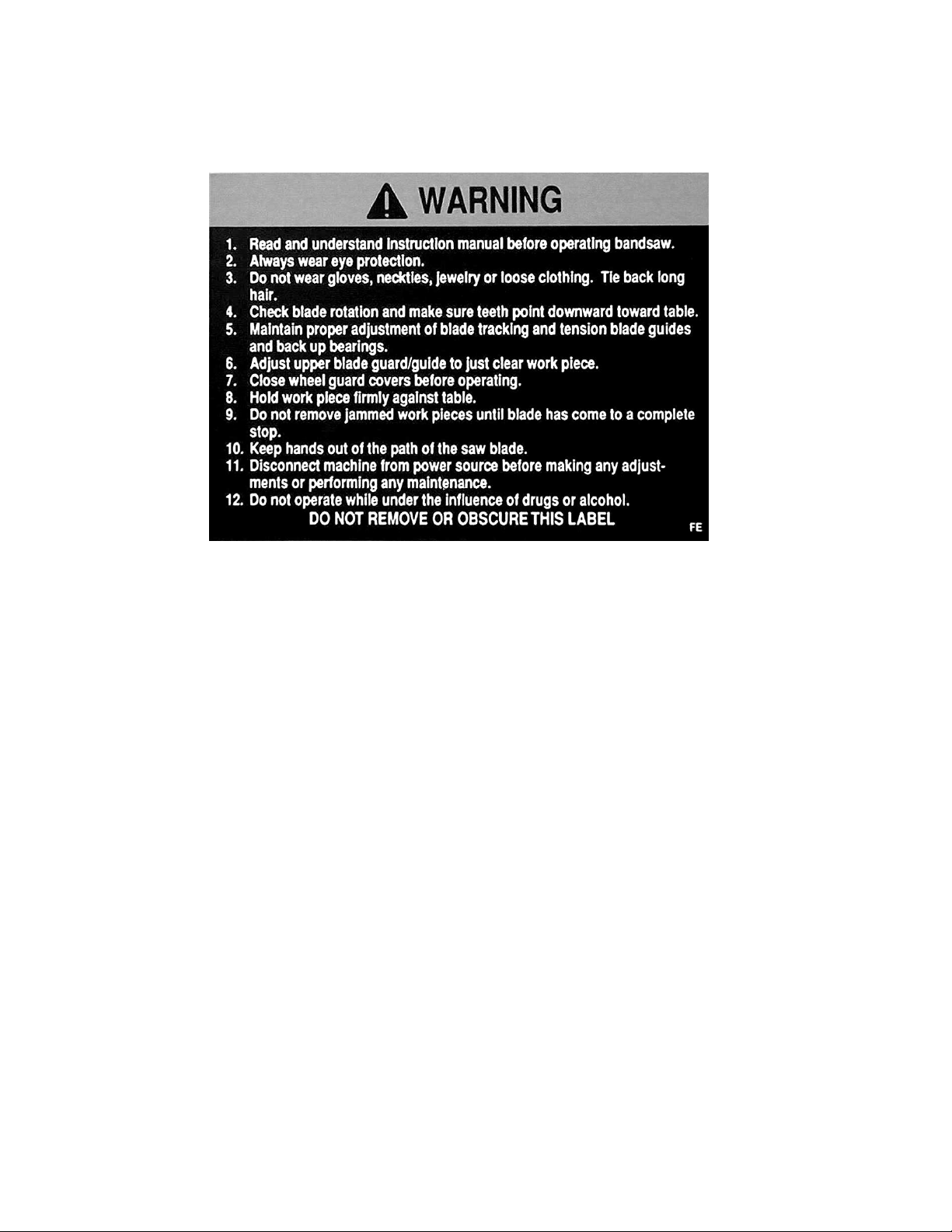
SAFETY DECAL
Familiarize yourself with the location and content of this decal on your machine.
Fig. 1
6
Page 7
Grounding Instructions
Caution: This tool must be grounded while in use to protect the operator from electric
shock.
In the event of a malfunction or breakdown, groundi ng pr ovides a path of l east r esi stanc e for
electric current to reduce the risk of el ec tric shock. This tool is equipped with an el ec tric cor d
having an equipm ent-grounding conduc tor and a grounding plug. The plug must be plugged into a
matching outlet that is properly instal led and grounded in acc or danc e with all local codes and
ordinances.
Do not modi fy the plug provided. I f it will not fit the outlet, have the proper outlet i nstalled by a
qualified el ec trician.
Improper connection of the equi pment-grounding conductor can r esult in a risk of el ec tric shock.
The conductor, with insulat ion having an outer surface that is green with or without yellow stripes, is
the equipm ent-grounding conduc tor. If repair or r eplacement of the electric cord or pl ug is
necessary, do not connect the equipment-grounding conduc tor to a live terminal.
Check with a qualified electr ician or service personnel if the groundi ng instructions are not
completely understood, or if in doubt as to whether the t ool is properl y gr ounded. Use only three
wire extensi on c or ds that hav e three-prong grounding plugs and three-pole receptacles that accept
the tool’s plug.
Repair or replace a damaged or worn cord immediately.
115 Volt Operation
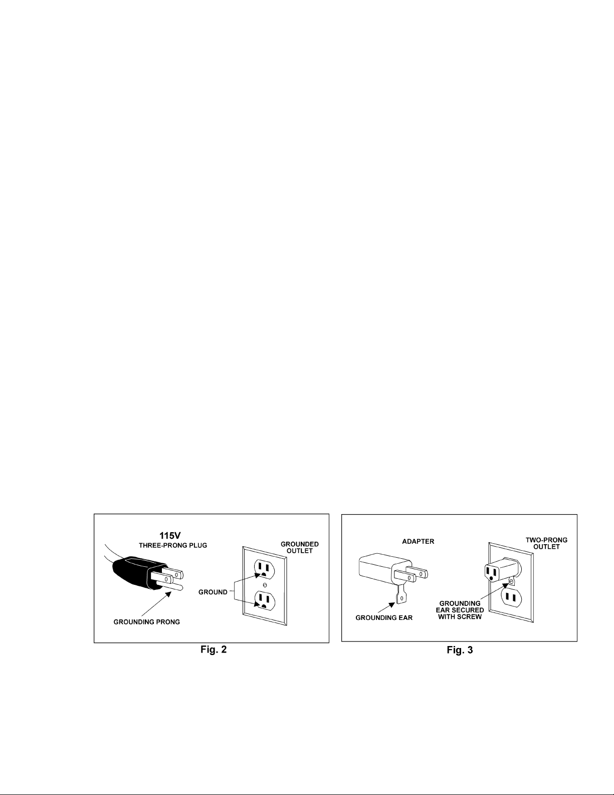
As received fr om the factory, your bandsaw is ready to run at 115 volt oper ation. T his bandsaw,
when wired for 115 volts, is intended for use on a circuit that has an outlet and a plug t hat looks like
the one illustrated in Fig. 2. A temporary adapter, like the adapter in Fig. 3, may be used to connec t
this plug to a two-pole receptacle, as shown in Fig. 3, if a properly gr ounded outlet is not availabl e.
The tempor ary adapter should onl y be used until a proper ly grounded outlet can be installed by a
qualified el ec trician. This adapter is not applicable in Canada. The green colored rigi d ear , lug,
or tab, ex tending from t he adapter, must be connected to a permanent ground such as a properly
grounded outlet box, as shown in Fig. 3.
Page 8
230 Volt Operation
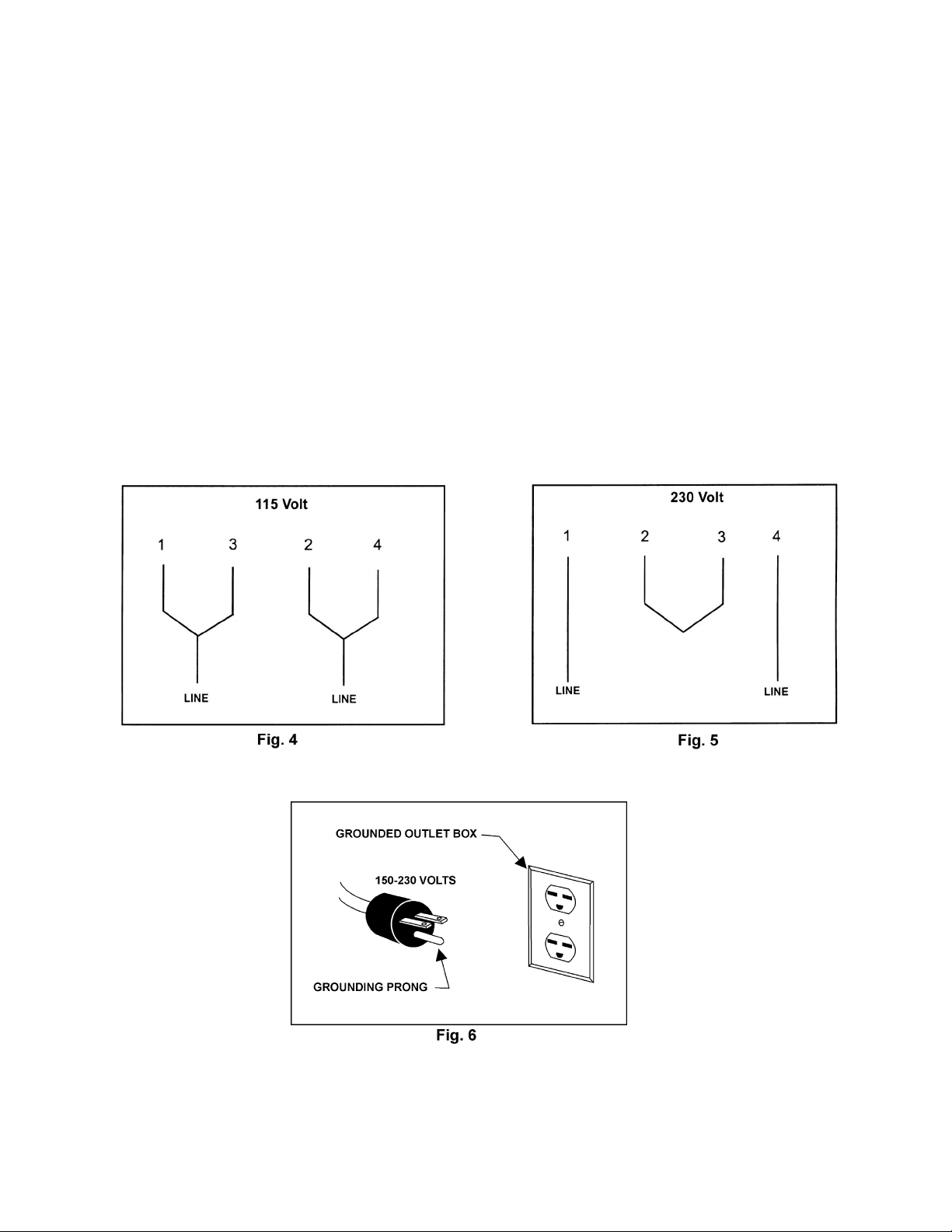
If 230V, single-phase operation is desired, the following instr uc tions must be foll owed:
1. Disconnect the machin e f rom the po wer source.
2. This band saw is supplied with f our motor leads that are connect ed for 115V operation, as
shown in Fig. 4. Rec onnec t these four motor l eads for 230V operation, as shown in Fig. 5.
3. The 115V attachment plug supplied with the band saw must be replaced with a UL/CSA listed
plug suitable for 230V oper ation (Fig. 6). Contact your l ocal authorized WMH Tool Group
servi ce center or qual ified elect r ician for proper procedures to install the plug. The band saw
must comply with all loc al and national codes after the 230 volt plug is instal led.
4. The band saw with a 230 volt plug should only be connected to an out let having the same
confi gur ation (Fig. 6). No adapter is available or should be used with the 230 vol t plug.
Important: In al l cases (115 or 230 vol t s) , make certain the receptacle i n questi on is properly
grounded. If you are not sure, have a registered electrician check the receptacle.
8
Page 9

Specifications: JWBS-14DX Band Saw
Stock Number.................................................................................................................710115K
Cutting Capacity (height)............................................................................................................6”
Cutting Capacity (widt h) .....................................................................................................13-1/2”
Minimum Blade Width.............................................................................................................1/8”
Maximum B lade Width............................................................................................................3/4”
Blade Length......................................................................................................................93-1/2”
Blade Speed .............................................................................................................. 3000 SFPM
Table Size.......................................................................................................................15” x 15”
Table Slot Size........................................................................................................3/8”D x 3/4”W
Table Hei ght from Floor .....................................................................................................43-1/2”
Table Tilt (L-R)..............................................................................................................45°R / 10°
Dust Chute Diameter......................................................................................................... 4” O.D.
Overall Dimensions........................................................................................68”H x 26”W x 19”D
Motor.............................................................................1.25 HP, 1Ph, 115/230V (prewired 115V)
Net Weight (appr ox.).......................................................................................................... 185 lb.
Shipping Weight (approx.).................................................................................................. 197 lb.
The specif icati ons i n this manual are given as general information and ar e not binding. W M H Tool
Group reserves the right to effect, at any time and without pr ior noti c e, alterations to parts, fit tings,
and accessory equipment deemed necessary for any reason whatsoever.
9
Page 10

Fasteners for JWBS-14DX
A. Saw Body to Stand
4 – M8x40 hex c ap scr ews
(approx. 1-1/2" long)
8 – M8 fl at washers
4 – M8 lock washers
4 – M8 hex nuts
B. Strain Relief Plate to Stand
2 – M5x12 pan head m achine screws
C. Belt Co ver t o Base
2 – Knobs
D. Trunnion Bracket to Saw Body
2 – M8x30 hex c ap scr ews
(approx. 1-1/4" long)
2 – M8 lock washers
1 – M8x80 hex c ap scr ew (for tabl e stop -
(approx. 3-1/8” long)
1 – M8 hex nut
Page 11

Receiving
Open both shipping containers and check for shipping
damage. Report any damage immediately to your
distributor and shipping agent. Read the instruc tion
manual t horoughly for assembly, maint enanc e and
safety instructions.
Contents of Shipping Containers
Container One
1 Stand with motor
Container Two
1 Saw body
1 V-belt
1 Belt cover
1 Trunnion support br ac k et
1 Table
2 Table loc k knobs
1 Table pin
1 Table insert
1 Fastener package (see fastener page)
1 Instruction manual
1 Warranty card
Too ls Required for Assembly
3/8" to 1" combination wrench set and
adjustable wrench
#1 and #2 cross point screwdri vers
Assembly
Exposed met al surfaces, such as the table, have
been given a protective coating. This should be
cleaned with a soft clot h and sol vent , such as
kerosene. Do not use an abrasive pad, and do not
get solvents on plastic par ts.
1. Remov e belt cover from inside of stand.
2. Place cabinet stand upright on a lev el surface. If
desired, the stand can be further stabilized by
securing it to the floor with l ag screws through
the inside cor ner holes. If using a mobile base,
lock the cast er s before assembling or operating
the band saw.
3. Wi th the aid of a second person, lift the saw
body out of the shipping cont ainer and place
onto stand top. Be sure front of saw (with JET
logo) f ac es stand front (JE T logo).
11
Page 12

WARNING
Saw body is heavy! Use caution when lifti ng
and stabilize until firmly attached to the
stand! Failure to comply may cause
serious injury!
4. Line up holes in saw body with holes in the top
of the stand. Fasten saw body to the stand with
four M8 x 40 hex cap screws, eight M8 washers,
four M8 lock washers, and four M8 hex nuts (as
shown in item A , page 10).
5. Push motor cord and strain relief pl ate through
the opening in the side of the stand (Fig. 8).
Fasten the strai n r elief plate t o the stand with
two M5 x 12 pan head m ac hine screws (shown
in item B, page 10).
6. Check the alignment of the pulleys by placing a
straight edge against the flat sides of the motor
and wheel pulleys (F ig. 8a). If the pulleys lie in a
straight plane (Fig. 8b) they are aligned. If they
do not lie in a straight plane, loosen the set
screw on one of the pulleys and shift the pulley
in or out until both pulleys lie in a straight plane.
Tighten set screw.
7. Open the lower door, and place the v-belt
around the mot or pulley and the wheel pulley
(see Fig. 8a).
8. Loosen the nuts on the four motor m ounting
bolts (Fig. 8c) and tension the v - belt by pushing
down on the motor. Tighten the four motor
mounti ng nuts.
12
Page 13

9. The v-belt is properly tensioned when f inger
pressure between the two pulleys causes
approximatel y 1/2" deflecti on ( fig. 8d).
10. Screw the two small k nobs (Fig. 9) into the
threaded holes in the saw body. Slide the pulley
cover down over the knobs, and tighten t he
knobs.
11. Attach trunnion support to saw body with two M8
x 30 hex c ap scr ews and two M8 lock washers
(as in item D, page two). See Figure 12.
12. Thread nut on to table stop bolt ( Fig. 12) and
attach to t r unnion support bracket as shown.
13
Page 14

13. To mount t he table, remove pin and insert from
the table (Fig. 13).
14. Rotate the table so that the saw blade will slide
through the slot in the table. Then orient the
table so the screws will slide into the holes on
the trunnion support brac ket. A ttach loc k k nobs
to these screws (Fig. 13).
15. Replace pin and i nsert .
16. Connect the plugs of the mot or cord and switch
cord (Fi g. 13a).
17. Transportation and handling may hav e c aused
some fastener s to loosen. Befor e operating,
check all screws, bolts, and nuts to make sure
they are snug. Operate machi ne only af ter
reading the entire manual including blade
tracking, blade guide adjustment s, and safety
rules.
Tilting the Table
WARNING
Unplug the machine from the power
source before making an y repair or adjustment!
Failure to comply may cause serious injury!
1. Loosen two lock knobs (Fig. 14).
2. Tilt table up t o 45 degr ees to the right or up to
10 degrees to the left, using the scale mounted
to the trunnion.
3. Tighten t wo l oc k k nobs (F ig.14).
Note: Tabl e stop must be rem oved t o tilt table to the
left.
14
Page 15

Adjusting 90°°°° Table Stop
1. Disconnect machin e f rom the po wer source.
2. Loosen lock knobs (Fi g. 14) and tilt tabl e left
until it rests against t able stop.
3. Use a square placed on the tabl e and against
the blade (Fig. 15) to see i f the t able is 90
degrees to the blade.
4. If an adjustment is necessary, loosen lock
knobs, tilt table to the right, and lock in place.
5. Loosen jam nut and t urn table stop (F ig. 14) l eft
or right to raise or lower the stop. Tighten jam
nut to hold t able stop in pl ac e.
6. Unlock table, ti lt back ont o table rest and
confi r m tabl e is 90 degrees with the blade.
7. If necessary, adjust scale pointer to zero.
Changing Blades
WARNING
Blade teeth are sharp! Use care wh en
handling the saw blade.
Failure t o comply may cause serious injury!
1. Disconnect machin e f rom power source.
2. Loosen blade tension by pushing up on t he
release lever (Fig. 16).
3. Remove the table insert and the table pin.
4. Open both wheel covers.
5. Remove the blade from between upper and
lower blade guides. Remove blade from upper
and lower wheels. Turn blade to direct through
slot in table.
6. Guide new blade thr ough table slot. P lace
blade in upper and lower blade guides. Note:
Make sure blade teet h point down toward table.
7. Place blade in the m iddle of the upper and
lower wheel.
8. Replace tabl e insert and tabl e pin.
15
Page 16

9. Tension and track blade before oper ating saw.
Find instructions for tensioni ng and tracking the
blade under "Adjusting Bl ade Tension" and
"Adjusti ng B lade Tracking".
Adjusting Blade Tension
1. Disconnect machin e f rom power source.
2. Turn blade tension knob (Fig. 16) clock wise to
tension blade. A gauge on the upper wheel
slide bracket indicates the approximate tension
according to the width of the blade. I nitially, set
the blade tension to correspond to blade wi dth.
3. As you become familiar with the saw, you may
find it necessary to change t he blade tension
from the initial setting. Changes in blade width
and the type of mater ial bei ng c ut will have an
effect on blade tension.
4. Keep in mind that t oo little or too much blade
tension can cause blade break age.
Adjusting Blade Tracking
WARNING
Disconnect machine fro m t he power source!
Never adjust b lade trackin g with t he
machine running!
Failure to comply may cause serious injury!
“Tracking” refer s t o how the blade is situated upon
the wheels while in motion. The blade should tr ac k in
the center of both wheels.
1. The blade m ust be pr oper ly tensioned before
adjusting blade tracki ng. The release l ever
should be in the down (tensioned) posi tion.
Make sure blade guides and bl ade bear ings do
not interfere with the blade.
2. Open top blade cover. Rotate the wheel
forward and observe the position of t he blade on
the wheel - it shoul d be in the center of the
wheel. See Fi g. 17a.
3. If adjustment is necessary, loosen wing nut (Fig.
17), and tighten tracking knob slight ly to move
blade toward rear of machine. Slightly
loosening the tracking knob will cause the blade
to track t oward t he front of the machine.
4. Tighten wing nut after blade is track ing in the
center of the wheel.
16
Page 17

Adjusting Upper Blade Guide Assembly
1. Disconnect machin e f rom the po wer source.
2. Loosen lock knob (A, Fig. 18) and raise or lower
upper blade guide assembly (B, F ig. 18) to just
above t he material being c ut.
3. Tighten lock knob. Mak e sure blade guide
blocks (C, Fig. 18) are still flat to the blade. If
adjustment is necessary, loosen lock k nob ( A ,
Fig. 18) and rotate assembly until guide blocks
are fl at to blade.
4. The upper blade guide is spring loaded. To
adjust the tensi on on the spring, remov e k nob
(A, Fi g. 18), tighten or loosen set screw (D, F ig.
18) until desired tension is reac hed, and replace
knob.
Adjusting Upper Blade Guide and
Blade Support Bearing
WARNING
Blade guard has been removed for p icture
clarity. Never o perate the bandsaw without
all guards in place and in workin g order!
Failure t o comply may cause serious injury!
1. Disconnect machin e f rom the po wer source.
2. Blade must already be tensioned and tracking
properly.
3. Loosen thumb screws (A, Fi g. 19) and move
guide blocks (B , Fig. 19) as close to the blade
as possible without pinc hing it.
4. Tighten t humb screws (A, Fi g. 19).
5. Loosen thumb screw (C, Fig. 19) and turn
knurled knob (D, Fig. 19) to move the guide
block brack et in or out unt il the front edge of the
guide blocks are just behind the " gullets" of the
saw teeth.
6. Tighten t humb screw (C, Fig. 19).
7. Loosen thumb screw (E, Fig. 19) and tur n
knurled knob (F, Fig. 19) to m ove the support
bearing (G, Fig. 19) in or out until the bear ing is
1/64" behind t he blade.
8. Tighten t humb screw (E, Fig. 19).
17
Page 18

9. The blade support bearing should be adjusted
so that the back edge of the blade overlaps the
front face of the ball bearing approximately 1/8".
To change position of the bear ing, remove
screw (H, Fig. 19) , and bearing (G , Fig. 19), and
back off knurl ed k nob ( F, Fi g. 19) completely to
remove the bearing shaft. Notice the bearing
holder on the shaf t is eccentric. Re-install the
bearing shaft , the bearing, and the screw.
Exam ine the overlap between the bearing f ace
and the blade. Change t he position of the
bearing shaft until the ov er lap is approx imately
1/8".
Adjusting Lower Blade Guides and Blade
Support Bearing
1. Disconnect machin e f rom the po wer source.
2. Blade must already be tensioned and tracking
properly.
3. Loosen thumb screws (A, Fi g. 20) and move
guide blocks (B , Fig. 20) as close to blade as
possible without pinching it.
4. Tighten t humb screws (A, Fi g. 20).
5. Loosen thumb screw (C, Fig. 20) and turn
knurled knob (D, Fig. 20) to move the guide
block brack et in or out unt il the front edge of the
guide blocks are just behind the " gullets" of the
saw teeth.
6. Tighten t humb screw (C, Fig. 20).
7. Loosen thumb screw (E, Fig. 20) and tur n
knurled knob (F, Fig. 20) to m ove the support
bearing (G, Fig. 20) in or out until the bear ing is
1/64" behind t he blade.
8. Tighten t humb screw (E, Fig. 20).
9. The blade support bearing should be adjusted
so that the back edge of the blade overlaps the
front face of the ball bearing approximately 1/8".
To change position of the bear ing, remove
screw (H, Fig. 20) and bear ing (G, Fig. 20), and
back off knurl ed k nob ( F, Fi g. 20) completely to
remove the bearing shaft.
10. Notice t he bear ing holder on t he shaft is
eccentric. Re-install the bearing shaft, the
bearing, and the scr ew. Examine the overlap
between the bearing face and the blade.
Change the position of the bearing shaft until
the ov er lap is approx imat ely 1/8". Re- tighten
thumb screw (E, Fig. 20).
18
Page 19

TROUBLE-SHOOTING (JWBS-14DX Band Saw)
PROBLEM POSSIBLE CAUSE SOLUTION
Saw stops or will not start 1. Saw unplugged 1. Check plug connections
2. Fuse blown or cir c uit breaker tripped 2. Replace fuse or reset
circuit breaker
3. Cord damaged 3. Replace cord
Does not make accur ate 1. Stop not adjusted correctly 1. Check blade with
45 deg. or 90 deg. cuts square and adjust stop
2. Angle poi nter not set accurately 2. Check blade with square
and adjust pointer
3. Miter gauge out of adjustment 3. Adjust miter gauge
Blade wanders during cut 1. Fence not aligned with blade 1. Check and adjust fence
2. Warped wood 2. Select another piece of
wood
3. Excessive feed rate 3. Reduce feed rate
4. Incorrec t blade f or c ut 4. Change blade to correct
type
5. Blade tension not set properly 5. Set blade tension
according to blade size
6. Guides not set pr oper ly 6. Adjust guides
Saw makes unsatisfac tory 1. Dull blade 1. Replace blade
cuts 2. Blade mount ed wrong 2. Teeth should point down
3. Gum or pitch on bl ade 3. Remove bl ade and c lean
4. Incorrec t blade f or c ut 4. Change blade to correct
type
5. Gum or pitch on table 5. Clean table
Blade does not come up 1. E xtension cor d too light or too long 1. Replace with adequate
size and to speed length cord
2. Low shop voltage 2. Contact your local electric
company
Saw vibrates excessively 1. B ase on uneven floor 1. Reposition on fl at, level
surface
2. Bad v-belt 2. Replace v-belt
3. Motor mount is loose 3. Tighten motor mount
hardware
4. Loose hardware 4. Tighten hardware
19
Page 20

Parts Breakdown
JWBS-14DX Body Assembly
20
Page 21

Part s List
JWBS-14DX Body Assembly
Index Part
No. No. Description Size Qty.
1 .........150100AW ................... Upper Arm Frame .............................................. ................................1
2 .........150037W......................Table.................................................................. ................................1
3 .........100038 .........................Table Pin ........................................................... ................................1
4 .........708719 .........................Guide Block....................................................... ................................ 4
5 .........150005A.......................Upper S uppor t Bracket P ost............................... ................................ 1
6 .........150006A.......................Suppor t Bracket ................................................. ................................ 2
7 .........150007A.......................Guide Post..................................................... ... ................................1
8 .........TS-1490021..................Hex Cap Screw..................................................M8x16...................... 2
9 .........TS-1550061..................Flat Washer.......................................................M8 ...........................1
10 .......150010A....................... Nut..................................................................... ................................ 4
11 .......990708 .........................Screw.................................................................M8x40...................... 2
12 .......TS-1482031..................Hex Cap Screw..................................................M6x16...................... 1
13 .......150013A....................... Thumb Screw.....................................................M6x16...................... 3
14 .......150014A....................... Thumb Screw ....................................................M6x12...................... 5
15 .......150015A....................... Upper S pac ing Sleeve ................................... ... ................................ 2
16 .......BB-6200ZZ...................Ball Bearing.......................................................6200ZZ .................... 2
17 .......990908 .........................Pan Head Screw*...............................................M6x8........................ 2
18 .......100002A....................... Upper Wheel Blade Guar d ................................. ................................1
19 .......TS-148201....................Hex Cap Screw..................................................M6X10..................... 2
20 .......TS-1550041..................Fl at Washer.......................................................M6 ...........................4
21 .......990651 .........................Lock Knob..........................................................M10x30 .................... 1
22 .......199037 .........................Table Insert........................................................ ................................ 1
23 .......992311 .........................Spring Pin.......................................................... ................................ 1
25 .......TS-1482041..................Hex Cap Screw..................................................M6x20...................... 2
26 .......150024 .........................Catch Knob........................................................ ................................ 2
27 .......TS-1551061..................Lock Washer*.....................................................M8 ......................2(2)*
28 .......150028W......................Inner Wheel Cover............................................. ................................ 1
29 .......155029W......................Outer Wheel Cover............................................ ................................ 1
30 .......100031 .........................Pin..................................................................... ................................ 4
31 .......990180 .........................Hex Head Bolt....................................................M16x55.................... 1
32 .......W F164030....................W asher..............................................................M16..........................2
33 .......TS-1540101..................Hex Nut..............................................................M16.......................... 1
34 .......JWBS14DX-134 ...........Base.................................................................. ................................1
35 .......110045 .........................Trunnion Suppor t Bracket................................... ................................ 1
36 .......100042 .........................Trunnion............................................................. ................................2
37 .......100051 .........................Scale.................................................................. ................................1
38 .......100041 .........................Trunnion Clamp Shoe ........................................ ................................ 2
39 .......TS-1491081..................Hex Cap Screw..................................................M10x50.................... 2
40 .......TS-1482021..................Hex Cap Screw..................................................M6x12...................... 6
41 .......110049 .........................Pointer............................................................... ................................ 1
42 .......990821 .........................Pan Head Screw................................................M5x6........................ 5
43 .......TS-1490151..................Hex Cap Screw*.................................................M8x80...................... 1
44 .......TS-1540061..................Nut*....................................................................M8 ...........................1
45 .......TS-1490051..................Hex Cap Screw*.................................................M8X30..................... 2
46 .......990554 .........................Lock Knob.......................................................... ...............................2
47 .......TS-152303....................Socket Set Screw...............................................M6x10...................... 1
48 .......100063 .........................Belt Pulley.......................................................... ................................ 1
49 .......992547 .........................Retaining Ring................................................... ................................ 1
50 .......110065 .........................Lower Wheel Shaft............................................. ................................ 1
21
Page 22

Part s List
JWBS-14DX Body Assembly
Index Part
No. No. Description Size Qty.
51........992009......................... Key.................................................................... 5x5x20......................2
52........BB-6204RS..................Ball Bearing.......................................................6204RS ....................2
53........990293......................... Hex Head Bolt (Left T hr ead) .............................. M8x25......................1
54........150054......................... Hex Head Bolt................................................... .................................2
55........150055......................... Lower Support Bracket Post............................... .................................1
56........150056......................... Switch Backing Plate......................................... .................................1
57........523028......................... Switch Box......................................................... .................................1
58........994542......................... Switch................................................................ .................................1
59........995001......................... Power Cord (Switch To Motor)........................... .................................1
60........995002......................... Power Cord (Switch To Power Soure)................ .................................1
61........990814......................... Self Tapping Screw............................................M3.5x19 ...................2
62........TS-1550021 .................Flat Washer ...................................................... M4............................2
63........TS-1533042 .................Phillips Pan Head Machine Screw...................... M5x12 ......................6
64........523024......................... Wire Clip ........................................................... .................................1
65........TS-1533032 .................Phillips Pan Head Machine Screw...................... M5x10 ......................4
66........150066......................... Stud................................................................... .................................2
67........150902......................... Lower Hinge ...................................................... .................................1
68........W F051210 ...................W asher.............................................................. M5............................2
69........JWBS14DX-169...........Lower Wheel Guard........................................... .................................1
70........100185......................... Lower Wheel ..................................................... .................................1
71........100025A ...................... Wheel Prot ec tor................................................. .................................2
72........100186......................... Upper Wheel ..................................................... .................................1
73........992522......................... Retaining Ring................................................... R35...........................2
74........BB-6202ZZ................... Bal l Bearing....................................................... 6202ZZ..................... 2
75........TS-1540083 .................Hex Nut.............................................................M12x1.25..................1
76........ .................................... Saw Blade (Local Purchase).............................. .................................1
77........990804......................... Self Tapping Screw............................................M4x8 ......................16
78........150901......................... Upper Hinge ...................................................... .................................1
79........150079......................... Catch................................................................. ................................ .2
80........150080......................... Clip.................................................................... .................................2
81........150081......................... Bracket.............................................................. .................................2
82........110070......................... Blade Guard...................................................... .................................1
83........990811......................... Self Tapping Screw............................................M3.5x12 ...................2
............100016ACP.................. Sliding Bracket Assy (includes items 84 thru 88) .................................1
84........100016A....................... Sliding Bracket .................................................. .................................1
85........100019......................... Shaft Hinge........................................................ .................................1
86........150086......................... Upper Wheel Shaft ............................................ .................................1
87........100021......................... Steel Pin............................................................ .................................2
88........992314......................... Spring Pin.......................................................... ................................. 1
89........100015A....................... Coil Spring......................................................... .................................1
90........150090......................... Square Nut........................................................ .................................1
91........990652......................... Lock Knob ......................................................... .................................1
92........NW080000...................Wing Nut........................................................... M8 ............................1
93........JWBS14DX-193...........Blade A djusting Scr ew....................................... .................................1
95........TS-1490071 .................Hex Cap Screw*................................................ M8x40......................4
96........TS-1550061 .................Flat Washer*...................................................... M8............................4
97........150097......................... Washer.............................................................. .................................2
98........994181......................... Steel Ball........................................................... .................................1
99........150099......................... Spring................................................................ ................................ .1
100......TS-1525011 .................Socket Set Screw ..............................................M10x10 ....................1
22
Page 23

Part s List
JWBS-14DX Body Assembly
Index Part
No. No. Description Size Qty.
101......150101 .........................Lower Wheel Blade Guar d ................................. ................................ 1
102......WE050000 ...................Gear Washer .....................................................M5 ........................... 2
103......998654 .........................Strain Relief....................................................... ................................2
104......100018 .........................Indicator............................................................. ................................1
105......WI 080000.....................Gear Washer .....................................................M8 ........................... 2
106......100174 .........................Fixed Collar ....................................................... ................................1
107......TS-1522031..................Socket Set Screw...............................................M5x10 ...................... 1
108......130044 .........................Fixed Collar ....................................................... ................................1
109......SS050100.....................Socket Set Screw...............................................M5x5........................ 1
110......TS-1550071..................Flat Washer.......................................................M10..........................1
111......100234 .........................Tension Lever Knob...........................................M8 ...........................1
112......100183 .........................Tension Lever Rod............................................. ................................ 1
113......NH121900....................Hex Nut..............................................................M12..........................1
114......100205 .........................Gasket...............................................................M8 ...........................1
115......100182 .........................Tension Lever.................................................... ................................ 1
116......100176 .........................Bushing.............................................................. ................................ 1
117......TS-2248202..................Socket Head Button Screw .................................M8x20...................... 1
118......100177 .........................Spacer............................................................... ................................ 1
119......TS-1490071..................Hex Cap Screw..................................................M8x40...................... 2
120......TS-1541031..................Nylon Lock Hex Nut ...........................................M8 ...........................2
121......TS-1550061..................Flat Washer.......................................................M8 ...........................6
122......100178 .........................Support Plate..................................................... ................................ 2
123......100179 .........................Fixed Base......................................................... ................................ 1
124......TS-2361081..................Lock Washer......................................................M8 ...........................2
125......TS-2248202..................Socket Head Button Screw .................................M8x20...................... 2
........... JWBS14-HK.................Hardware Kit (not shown)................................... ................................1
* included in hardware kit
23
Page 24

Parts Breakdown
JWBS-14DX Closed Stand Assembly
24
Page 25

Part s List
JWBS-14DX Closed Stand Assembly
Index Part
No. No. Description Size Qty.
1 .........150501W......................Stand................................................................. ............................... 1
2 .........150502W......................Door................................................................... ............................... 1
3 .........150503 .........................Door Latch Assembly (Items 4 & 5).................... ............................... 1
4 .........WBS14CS-04 ...............Washer.............................................................. ............................... 2
5 .........WBS14CS-05 ...............Pan Head Screw ................................................M4x5....................... 2
6 .........PG-M02........................Plaque ............................................................... ............................... 1
7 .........TS-1533031..................Flat Head Screw.................................................M5x10 ..................... 2
8 .........150508W......................Plate.................................................................. ............................... 1
9 .........998621 .........................Stran Relief ........................................................ ...............................1
10 .......TS-1533042..................Pan Head Screw*...............................................M5x12..................... 2
11 .......150511W......................Motor Plate........................................................ ............................... 1
12 .......100180 .........................Motor (TEFC).......................................1-1/4 HP, 1Ph, 115/230V....... 1
13 .......600013 .........................Motor Pulley....................................................... ............................... 1
14 .......VB-A50.........................V-Belt................................................................. ............................... 1
15 .......TS-1523011..................Set Screw ..........................................................M6x6....................... 1
16 .......100254 .........................Belt Cover.......................................................... ............................... 1
17 .......PWBS14-306................Knob*.................................................................M6x12..................... 2
20 .......TS-1490041..................Hex Head Bolt....................................................M8x25..................... 4
21 .......991516 .........................Square Neck Bolt...............................................M8x16..................... 4
22 .......TS-1550051..................Washer*.............................................................M8 ................... 16(4)*
23 .......TS-155108....................Lock Washer*.....................................................M8 ...................12(4)*
24 .......TS-1540061..................Nut*....................................................................M8 ...................12(4)*
26 .......995003A....................... Motor Cord......................................................... ...............................1
27 .......150527 .........................Pad.................................................................... ............................... 2
........... WBS14CS-HK..............Hardware Kit (includes it ems marked with *)....... ............................... 1
25
Page 26

Optional Accessories for JWBS-14DX Band Saw
708114 Three speed ki t for WBS-14CS
Produces speeds of 965, 1470, and 2465 S P FM. Includes four step motor pul ley,
intermediat e pulley, V -belts, fasteners, and mounting instr uc tions with parts l ist.
708718 JRF-14 Rip Fence Assembl y
Includes guide bars, rip fence assembly, fasteners, and mounting instructions with parts li st.
708717 JRB-14 Riser Block Kit
Increases depth of cut f r om 6" m aximum to 12" maximum. Includes 6" cast block, long
frame bolt, front and bac k blade guards, and mounting instruc tions with parts list.
(Blade not included - r equires 105-1/2" bl ade) .
708716 JMG-14 Mi ter Gauge Assembly
For straight and angle cutt ing. Includes guide bar, pivoting support body, and adjustable
stops.
708719 JRB-14 Blad e Block Set
Includes upper and lower replacement bloc k s made from a non-m etallic composite material
with a dry lubr icant to reduce friction and heat.
26
Page 27
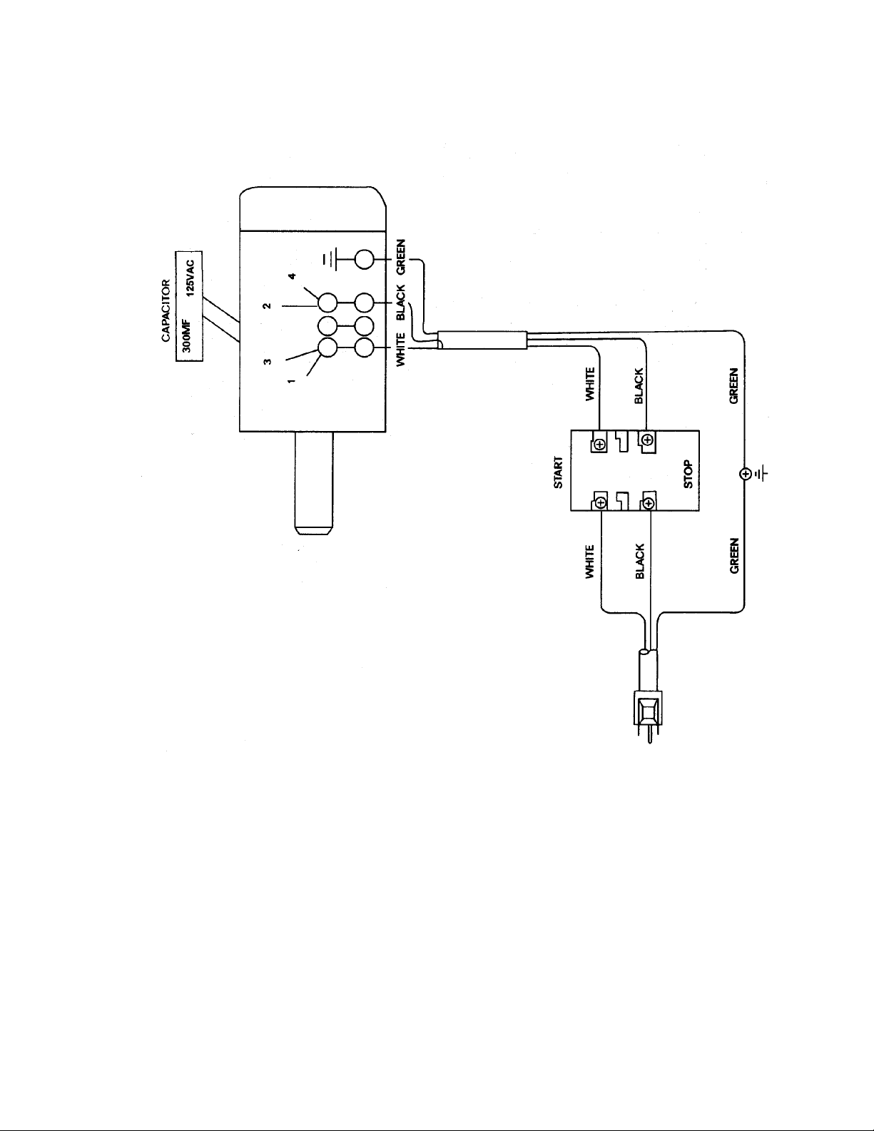
JWBS-14DX Electrical Schematic – 115V
27
Page 28

JWBS-14DX Electrical Schematic - 230V
WMH TOOL GROUP
2420 Vantage Drive
Elgin, IL 60123
Ph: 800-274-6848
www.wmhtoolgroup.com
28
 Loading...