

Page 1

This .pdf document is bookmarked
Operating Instructions and Parts Manual
10-inch Band Saw
Model JWBS-10OS
JET
427 New Sanford Road
LaVergne, Tennessee 37086 Part No. M-707200
Ph.: 800-274-6848 Revision A3 04/2014
www.jettools.com Copyright © 2014 JET
R
CUS
162920
Page 2

Warranty and Service
JET warrants every product it sells against manufacturers’ defects. If one of our tools needs service or repair, please contact
Technical Service by calling 1-800-274-6846, 8AM to 5PM CST, Monday through Friday.
Warranty Period
The general warranty lasts for the time period specified in the literature included with your product or on the official JET
branded website.
• JET products carry a limited warranty which varies in duration based upon the product. (See chart below)
• Accessories carry a limited warranty of one year from the date of receipt.
• Consumable items are defined as expendable parts or accessories expected to become inoperable within a
reasonable amount of use and are covered by a 90 day limited warranty against manufacturer’s defects.
Who is Covered
This warranty covers only the initial purchaser of the product from the date of delivery.
What is Co vered
This warranty covers any defects in workmanship or materials subject to the limitations stated below. This warranty does not
cover failures due directly or indirectly to misuse, abuse, negligence or accidents, normal wear-and-tear, improper repair,
alterations or lack of maintenance.
Warranty Limitations
Woodworking products with a Five Year Warranty that are used for commercial or industrial purposes default to a Two Year
Warranty. Please contact Technical Service at 1-800-274-6846 for further clarification.
How to Get Technical Support
Please contact Technical Service by calling 1-800-274-6846. Please note that you will be asked to provide pro of of ini tial
purchase when calling. If a product requir es further inspection, th e Technic a l Service representati v e will expla in and assist
with any additional action needed. JET has Authorized Service Centers located throughout the United States. For the name of
an Authorized Service Center in your area call 1-800-274-6846 or use the Service Center Locator on the JET website.
More Informa t io n
JET is constantly adding new products. For complete, up-to-date product information, check with your local distributor or visit
the JET w ebsite.
How S tate Law Applies
This warranty gives you specific legal rights, subject to applicable state law.
Limitations on This Warranty
JET LIMITS ALL IMPLIED WARRANTIES TO THE PERIOD OF THE LIMITED WARRANTY FOR EACH PRODUCT.
EXCEPT AS STATED HEREIN, ANY IMPLIED WARRANTIES OF MERCHANTABILITY AND FITNESS FOR A PARTICULAR
PURPOSE ARE EXCLUDED. SOME STATES DO NOT ALLOW LIMITATIONS ON HOW LONG AN IMPLIED WARRANTY
LASTS, SO THE ABOVE LIMITATION MAY NOT APPLY TO YOU.
JET SHALL IN NO EVENT BE LIABLE FOR DEATH, INJURIES TO PERSONS OR PROPERTY, OR FOR INCIDENTAL,
CONTINGENT, SPECIAL, OR CONSEQUENTIAL DAMAGES ARISING FROM THE USE OF OUR PRODUCTS. SOME
STATES DO NOT ALLOW THE EXCLUSION OR LIMITATION OF INCIDENTAL OR CONSEQUENTIAL DAMAGES, SO THE
ABOVE LIMITATION OR EXCLUSION MAY NOT APPLY TO YOU.
JET sells through distributors only. The specifications listed in JET printed materials and on official JET website are given as
general information and are not binding. JET reserves the right to effect at any time, without prior notice, those alterations to
parts, fittings, and accessory equipment which they may deem necessary for any reason whatsoever. JET
are not sold in Canada by JPW Industries, Inc.
Product Listing with Warranty Period
90 Days – Parts; Consumable items; Light-Duty Air Tools
1 Year – Motors; Machine Accessories; Heavy-Duty Air Tools; Pro-Duty Air Tools
2 Year – Metalworking Machinery; Electric Hoists, Electric Hoist Accessories; Woodworking Machinery used
for industrial or commercial purposes
5 Year – Woodworking Machinery
Limited Lifetime – JET Parallel clamps; VOLT Series Electric Hoists; Manual Hoists; Manual Hoist
Accessories; Shop Tools; Warehouse & Dock products; Hand Tools
NOTE: JET is a division of JPW Industries, Inc. References in this document to JET also apply to JPW Industries, Inc., or any
of its successors in interest to the JET brand .
®
branded products
2
Page 3

Table of Contents
Warranty and Servic e .......................................................................................................................................... 2
Table of Contents ................................................................................................................................................ 3
Warning ............................................................................................................................................................... 4
Introduction .......................................................................................................................................................... 6
Specifica tio ns ...................................................................................................................................................... 6
Feature s .............................................................................................................................................................. 6
Shipping Contents ............................................................................................................................................... 7
Contents of Shipping Container ........................................................................................................................ 7
Contents of Hardware Bag ............................................................................................................................... 7
Assembly ............................................................................................................................................................. 8
Stand ............................................................................................................................................................... 8
Table Installation .............................................................................................................................................. 8
90º Tabl e Stop ................................................................................................................................................. 9
Rail Guide and Fenc e ....................................................................................................................................... 9
Adjustments ....................................................................................................................................................... 10
Tilting the Table .............................................................................................................................................. 10
90º Tabl e Stop Adjustment ............................................................................................................................. 10
Changing Blades ............................................................................................................................................ 11
Adjusting Bl ade Tension ................................................................................................................................. 11
Upper Blade Guide P osi tioning ....................................................................................................................... 12
Blade Guide Adjustm ent ................................................................................................................................. 12
Operating Contr ols ............................................................................................................................................. 13
Adjusting Bl ade Trac ki ng ................................................................................................................................ 11
Replacing the Poly V-Belt ............................................................................................................................... 14
Adjustin g Poly V-Be lt Te n sion......................................................................................................................... 1 4
Grounding Inst r uc tions ....................................................................................................................................... 15
General Information ........................................................................................................................................ 15
115 Volt Operati on ......................................................................................................................................... 15
Extension Cords ............................................................................................................................................. 15
Troubleshooting ................................................................................................................................................. 1 6
Optional Accessories ......................................................................................................................................... 1 7
10" Band Saw Blades ..................................................................................................................................... 17
Parts .................................................................................................................................................................. 18
Replacement Parts ......................................................................................................................................... 18
Parts List ........................................................................................................................................................ 18
Assembly Drawing.......................................................................................................................................... 2 1
Electri c al Connec tions ....................................................................................................................................... 2 2
3
Page 4

Warning
1. Read and understand the ent ire owner's manual bef or e att em pting assembly or operation.
2. Read and understand the warnings posted on the m achine and in this manual. Failure to comply with all of
these warnings may c ause serious i njury.
3. Replace the warning labels if they become obscured or removed.
4. This band saw i s designed and intended f or use by properl y trained and ex perienced personnel onl y. If you
are not familiar with the proper and safe operation of a band saw, do not use until proper training and
knowledge have been obtained.
5. Do not use this band saw for other t han i ts intended use. If used for other purposes, JET disclaims any real or
implied warrant y and holds itself harmless from any injury t hat m ay result from that use.
6. Always wear approved safety glasses/f ace shields while using this band saw. Everyday eyegl asses only hav e
impact resistant lenses; they are not safety gl asses.
7. Before operating thi s band saw, r emove tie, rings, watches and other jewelry, and roll sl eev es up past the
elbows. Remove all loose clothing and confine long hair. Non-slip footwear or anti-skid floor strips are
recommended. Do not wear gl ov es.
8. Wear ear protector s (plugs or muffs) during ext ended peri ods of oper ation.
9. Some dust created by power sanding, sawing, grinding, drilling and other construction activities contain
chemicals known to cause cancer, birth defects or other reproductive harm. Some examples of these
chemicals are:
• Lead from lead based paint.
• Crystalli ne sil ic a from bricks, cement and other m asonry pr oduc ts.
• Arsenic and chromium from chemically treated lumber .
Your risk of ex posure varies, depending on how of ten you do this type of work. To reduce your exposure to
these chemical s, work in a well-ventil ated area and work with approved safety equipment, such as face or
dust masks that are specifically designed to fil ter out microscopic partic les.
10. Do not operate this machi ne while tired or under the influence of drugs, alcohol or any medication.
11. M ak e c er tain the switch is in the OFF position before connecting the m achi ne to t he power supply .
12. M ak e c er tain the machine is properly grounded.
13. M ak e all machine adjustments or maintenance with the machine unplugged from the power source.
14. Rem ove adjusti ng keys and wrenches. F orm a habi t of checki ng to see that keys and adjusti ng wrenche s are
removed from the machine before turning it on.
15. K eep safety guards in pl ace at all tim es when the machine i s in use. If removed f or maintenance purposes,
use extreme caution and replace the guards immedi ately.
16. Check dam aged parts. Before further use of t he machine, a guard or other part that is damaged should be
carefully checked to determine that it will operate properly and perform its intended function. Check for
alignment of m ov ing par ts, binding of moving parts, breakage of par ts, mounting and any other c onditions that
may affect it s operati on. A guard or other part that is damaged shoul d be pr oper ly repaired or replaced.
17. P r ov ide for adequate space surroundi ng work area and non-glare, ov er head l ighting.
18. K eep the floor around the machi ne cl ean and free of scrap material, oil and grease.
19. K eep v isitors a safe distance from the work area. Keep children away.
20. M ak e y our workshop chi ld proof with padloc k s, m aster switc hes or by r em ov ing starter keys.
21. Giv e your work undivi ded attenti on. Looking around, carry i ng on a conversation and “horse-pl ay” are careless
acts that can resul t in seri ous i njury.
4
Page 5

22. Mai ntain a balanced stanc e at all times so that you do not fall or lean against the blade or other moving parts.
Do not overreach or use excessive force to perform any machine operation.
23. Use the ri ght t ool at the corr ect speed and f eed rate. Do not for ce a tool or attac hment to do a job f or which it
was not designed. The right tool will do the job better and safer.
24. Use recom mended accessories; improper accessories may be hazardous.
25. Maintain tools with care. Keep blades sharp and clean for the best and safest performance. Follow
instructions for lubricating and changing accessories.
26. Turn off the machine befor e cleaning. Use a brush or compressed air t o remove chips or debris — do not use
your hands.
27. Do not stand on the machine. Seri ous i njur y c ould occur if the machine tips over.
28. Nev er leave t he machine running unat t ended. Turn t he power off and do not l eave the machine unti l it c omes
to a complete stop.
29. Remove loose items and unnecessary work pieces from the area before starting the machine.
Familiariz e you rself with the following safety no tices used in this manual:
This means that if precautions are not heeded, it may result in minor injury and/or
possible machine damage.
This means that if precaution s are not heeded, it may result in serious injury or possibly
even death.
- - SAVE THESE INSTRUCTIONS - -
5
Page 6
Introduction
This manual is provided by JET covering the safe operation and maintenance pr ocedur es for the JET model JWBS-10OS
band saw. This manual contains instructions on installation, safety precautions, general operating procedures, maintenance
instructions and parts breakdown. This machine has been desi gned and constructed to provide years of trouble free oper ati on
if used in accordance with instructions set forth in this manual. If there are any questions or comm ents, please cont act either
your local supplier or JET can also be reached at our web site: www.jettools.com.
Specifications
Model Number ....................................................................................................................................... JWBS-10OS
Stock Number ............................................................................................................................................... 707200
Band Saw Size (in.) .............................................................................................................................................. 10
Cutting Capacity (height) (in.) .............................................................................................................................4-1/8
Cutting Capacity (wi dth) (in.) ..............................................................................................................................9-1/2
Maximum Rip Left of Blade w/Fence (in.)................................................................................................................. 5
Maximum Rip Right of Blade w/Fence (in.) .............................................................................................................. 5
Blade Length (in.) ............................................................................................................................................ 67-1/2
Blade Speed (FPM) ........................................................................................................................................... 2750
Minimum Blade Wid th (in.) ....................................................................................................................................1/8
Maximum Blade W idth (in.) ...................................................................................................................................1/2
Table Size (in.) .................................................................................................................................. 13-1/8 x 13-3/8
Table Size with Extension (in.) ................................................................................................................. 13-1/8 x 19
Table Tilt (degrees)...................................................................................................................................... 0° to 45°
Table Height from Fl oor (in.) ............................................................................................................................ 42-1/2
Wheel Diameter (in.) ............................................................................................................................................. 10
Dust Chute Diameter (in.) ....................................................................................................................................... 4
Overall Dimensions without stand (in.) .......................................................................................... 27 L x 16 W x 33 H
Overall Dimensio n s with s tand (in.) ............................................................................................. 30 L x 18 W x 60 H
Stand Dimens ions ( in.) ......................................................... 25-3/4H; Base: 18-1/2L x 21W; Top: 13-1/2L x 16-1/2W
Motor ........................................................................................................................................... 1/2 HP, 1Ph, 115V
Net Weight (a p prox.) (lbs .) .................................................................................................................................... 71
Shipping Weight (approx.) (lbs.) ............................................................................................................................ 75
The above specifications were current at the time this manual was published, but because of our policy of continuous
improvement, JET reserves the right to change specifications at any time and without prior notice, without incurring
obligations.
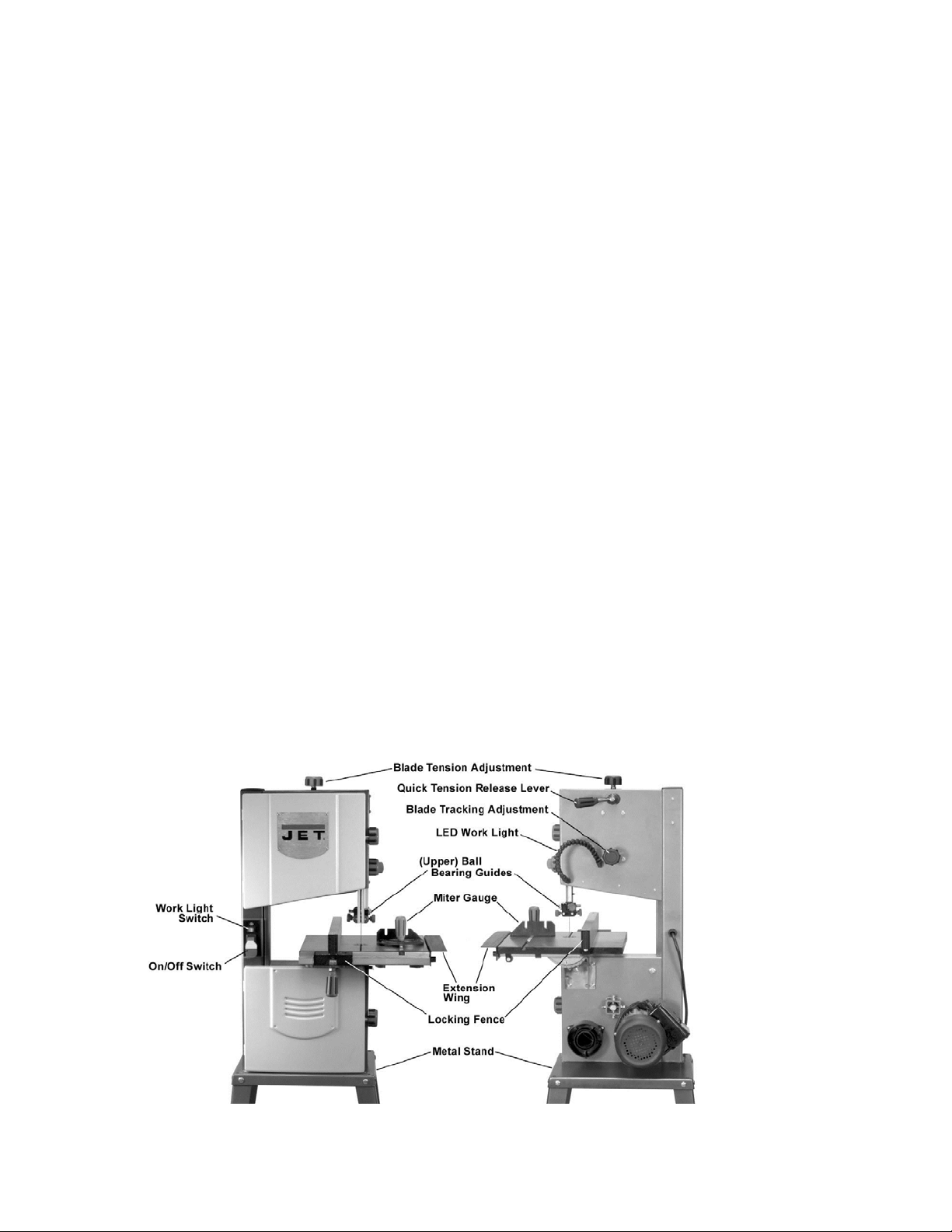
Features
6
Page 7
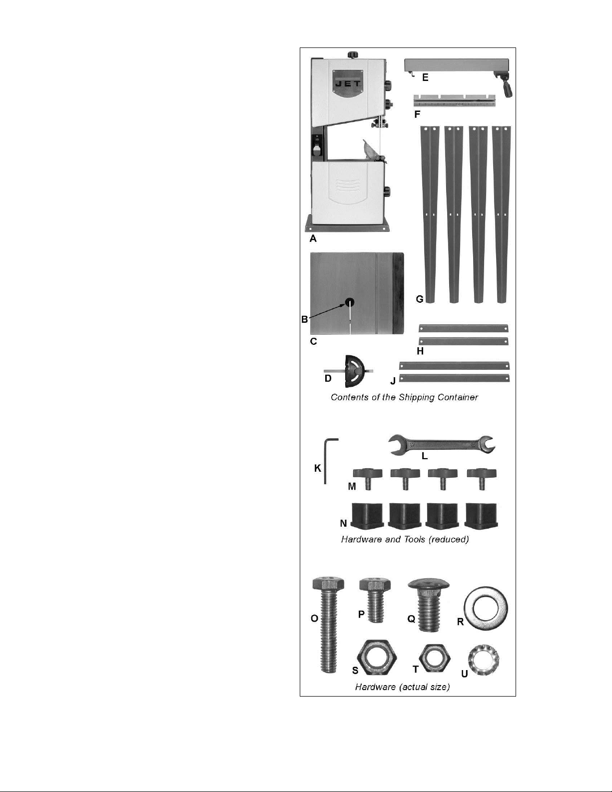
Shipping Contents
Remove all contents from the shipping carton. Do
not discard the c arton or packing material until the
band saw is assembled and is running
satisfactorily.
Compare the content s of the carton against the list
of parts in Contents of Shipping Container (below).
The letter identification i n the list corresponds to the
items shown at ri ght. This is your k ey for ident ifying
the parts used throughout t he Assembly section for
easy reference.
Remove the protectiv e coating that i s applied to the
table with a house hold grease and spot r emover.
Contents of Shipping Container
01 Band Saw (A)
01 Table Insert (B)
01 Table (C)
01 Miter Gauge (D)
01 Fence (E)
01 Rail Guide (F)
04 Stand Leg (G)
02 Short Support Plate (H)
02 Long Support Plate (J)
01 Owner's Manual (not shown)
01 Warranty Card (not shown)
01 Hardware Bag (see below for contents)
Contents of Hardware Bag
(p/n JWBS10OS-HB)
01 Hex Wrench 3mm (K)
01 Combination Wrench 10/13mm (L)
04 Rail Lock Knob (M)
04 Rubber Foot (N)
01 M6x32 Hex Cap Screw (O)
04 M6x12 Hex Cap Screw (P)
16 M8x16 Carriage Bolt (Q)
20 M8 Flat W asher (R)
16 M8 Hex Nut (S)
01 M6 Hex Nut (T)
04 M6 External Tooth Lock Washer (U)
Tools Required for Assembl y & Adj ustments
The tools listed below are not included but are
required for assembly.
2 14mm Open End Wrench
1 Cross Point Screw Driver
1 Combination Square
Shipping Contents
7
Page 8
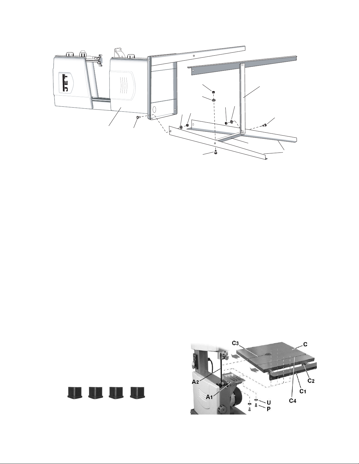
Assembly
S
3
R
3
R
2
S
2
S
1
R
1
L
Q
2
A
Q
1
Stand
Referring to Fi gur e 1:
1. Place the band saw (A) on its back as
shown above, either on the floor or
preferably on a workbench.
2. Assemble four legs (G) to the inside of the
base of the band saw, securing each leg
with two ea. M8x16 carr iage bolts (Q
flat washers (R
Hand-tighten only at this time.
3. Attach a long plate (L) to the rear legs as
shown in Figure 1. Secure with 2 ea M8x16
carriage bolts (Q
and M8 hex nuts (S
this time.
4. Attach the remaining long plate to the front
legs in the same manner described above,
hand-tightening only
5. Attach two shor t plates (K) to the right legs
and left legs in the same manner. Secure
each leg with 2 ea M8x16 carriage bolts
3), M8 flat washers (R3), and M8 hex nut s
(Q
3). Hand-ti ghten only at this time.
(S
1) and M8 hex nuts (S1).
2), M8 flat washers (R2),
2). Hand-tighten onl y at
1), M8
Figure 1
Back
K
Q
3
Front
G
8. Tighten all nuts with a 13mm socket or
wrench.
Table Installation
Referring to Fi gur e 3:
1. Loosen lock knob (C
1) out from the table (C).
(C
2. Orient the table (C) as shown, then
maneuver to allow the saw blade (A
pass through the slot (C
3. Line up four threaded mounting holes
underneath the table (C) with the four
mounting through-holes on the trunnion (A
Important: Adjust table so miter slot (C
parallel with saw blade (A
4. Secure with four each M6x12 hex cap
screws (P) and M6x12 external tooth lock
washers (U).
5. Tighten the screws (P) with a 13mm wrench.
2) and pull extension
2) to
3) to the center.
1).
4) is
2).
6. Slip rubber feet (Figure 2) onto the ends of
the stand legs.
Figure 2
7. Place the saw and stand upright on a level
surface. Make sure that all four legs are
contacting the surface.
Figure 3
8
Page 9

90º Table Stop
Referring to Fi gur e 4:
1. Slighty loosen the lock knob (C
4) and tilt the
table (C) up as shown.
2. Thread the M6 hex nut (T) approximately half
way onto the M6x32 hex cap screw (O). Then
thread the screw half way into the threaded
mounting hole (C
5) underneath the table.
Adjustment will be m ade later.
Rail Guide and Fence
Installation
1. Attach the rail guide (F, Fig. 5) to the front of
the table (C). Secure with four lock knobs (M).
Referring to F igur e 6:
2. Place fence assembly (E, Fig. 6) onto the
table (C) at the mit er slot .
The rear hook should engage the rear of the
table. The fence body should engage the rail
guide (F).
If the fence is not parallel to the miter slot:
3. Loosen two socket head c ap s c r ews (S
4mm hex wrench. End cap (S2) may need to
be removed.
1) with a
Figure 4
4. Adjust the fence so it is para lle l to the miter slot.
5. Lock the fence handle, securing it to the rail
guide (F), and verify that the fence is still
parallel to the miter slot.
6. Re-tighten two screws (S
to the fence body and repl ac e end cap (S
1) to secure the fence
2).
This completes the r ail guide and fence installation.
Fence scale adjustment
Referring to Fi gur e 6:
1. Place fence assembly (E) onto the table (C)
against the saw blade and lock.
If the hairline on t he scale indicator does not point
to zero:
2. Remove fence assembly (E).
3. Loosen the screw (S
3) that secures the scale to
the rail guide (F).
4. Repeat step 1, then slide the scale until the
hairline on the scale indicator points to zero.
5. Being caref ul not to move the scale, unlock and
lift fence from the table.
6. Tighten screw (S
3) to secure scale.
If further adjustment is needed, lock knobs (M) c an
be loosened to a llow ad jus t ment of the rail guide (F).
Figure 5
Figure 6
9
Page 10

Adjustments
Unplug the machine from the
power source before making any repairs or
adjustments. Failure to comply may cause
serious injury.
Tilting the Table
Referring to Fi gur e 7:
1. Loosen the lock knob (A).
2. Tilt table (C) up to 50 degrees m aximum to the
right or down 5 degrees to the left. The angle
can be read on the scale (B) on the trunnion
bracket.
Note: Table perpendicular (90º) to the blade
corresponds to a scale indication of 0º.
3. Tighten the lock k nob (A).
Note: The table stop (E) must be adjusted t o permit
the table to tilt to the left.
Figure 7
90º Table Stop Adjustment
Adjusting the table stop
The table stop (E, Fig. 7) is typic ally set to stop the
table at 90º (perpendicular) with the blade.
1. Disconnect machine from power source.
2. Loosen lock knob (A, Fig. 7); then tilt the table
(C, Fig. 7) down, bri nging it to rest against the
table stop (E, Fig. 7).
3. Use a square (J, Fig. 8) placed on the table
(C, Fi g. 8) and against the blade (H, Fig. 8) to
see if the table is 90º to the blade.
4. If an adjustment is necessary, tilt the table up
to access the table stop (E, Fig. 7).
5. Loosen the jam nut (D, Fig. 7) and turn the
table stop (E, Fig. 7) in or out to raise or lower
the stop. Tighten the jam nut to hold the table
stop in place.
6. Til t the table back to level, letting it rest against
the stop and confirm table is 90º with the blade
as described in step 3.
For left tilt down to 5º, the table stop (E, Fig. 7)
must be adjusted further.
Figure 8
Adjusting the table tilt indicator
1. Set the table at 90º wit h the blade.
2. Confirm that the table tilt indicator (F, Fig. 8)
points to zero.
If adjustm ent is requi r ed:
3. Slightl y loosen screw securing i ndicator , adjust
indicator to point to zero; then re-tighten screw.
Figure 9
10
Page 11

Changing Blades
Bl ade teeth are sharp! Use care
when handling the saw blade. Failure to comply
may cause serious injury.
Note: The JWBS-10OS Band Saw comes
equipped with a 67.5"x.375"x.014"x6TPI blade
(Part No. JWBS10O S-8) factory installed.
1. Disconnect machine from power source.
2. Open both wheel covers (K, L, Fig. 9).
3. Loosen lock knob (G, Fig. 8) and pull exten-
sion (O, Fig. 9) away from the table (C).
4. Remove rail guide (F, Fi g. 5).
5. Release tension on the blade by moving the
tension handle (V, Fig. 10) to the right.
Referring to Fi gur e 9:
6. Remove blade (H) from upper and lower
wheels (M, R) and from between the upper and
lower blade guides (N, Q).
7. Remove the blade th rough the slot (P) in th e ta b le .
8. Guide the new blade through table slot (P)
leading wit h t he smooth edge. Place it around
the upper and lower wheels and into the upper
and lower blade guides (N, Q).
Note: The blade teeth should face the operator,
and they should point down toward the table.
9. Positi on the bl ade to track i n the middle of the
rubber tir es on the wheels (M, R).
10. Engage tension on the blade by moving the
quick tension handle (V, Fig. 10) to the left.
11. Replace rail guide (F, Fig. 5).
Before operating the saw, check that the blade is tracking
and has proper tension as described in Adjusting Blade
Tension and Adjusting Blade Tracking below.
the width of the bl ade.
4. Set the blade tension with knob (T) to correspond
to the blade width as marked on the gauge (X).
Note: A meter is recommended to preci sely set
tension the bl ade for the size of blade used.
Note 1: As you become mor e experienced wit h t he
saw, you may find it necessary t o change t he blade
tension from the initial setting. Changes in blade
width and the type of material being cut will have
an effect on blade tension.
Note 2: Keep in mind that too little or too much
blade tension can c ause bl ade br eak age.
Adjusting Blade Tracking
Referring to Fi gur e 10:
Disconnect machine from the
power source! Never adj ust blade tracking with
the machine running! Failure to comply may
cause serious inj ury!
Tracking refers to how the blade is situated upon
the wheels while i n motion. T he blade should t rack
in the center of both wheels .
The blade must be sli ghtly tensioned (see previ ous
section) bef ore adjusting bl ade tracki ng.
blade guides and bearings
interfere with the blade. If blade tracking is
required, blade guide adjustment is described on
the following page.
1. Open the top and bottom wheel covers. Rotate
the wheel forward by hand, and observe the
position of the blade on the wheel through the
window (S). It should be in the center of the
wheel.
If adjustm ent is necessary:
(N, Q, Fig. 9) do not
Make sur e
Adjusting Blade Tension
Referring to Fi gur e 10:
1. Disconnect machine from power source.
The blade tension knob (T) is used to adjust blade tension.
Note 1: The quick tension lever (V) must be engaged
before making tension adjustments with knob (T).
Note 2: All bearings on upper and lower guides
must be clear of blade (see Blade Guide and Guide
Bearing adjustments on following page).
2. Appl y just enough ten sion to tak e the slack out
of the blade.
3. Turn one wheel a few times to allow the blade
to position itself in the center of the tire.
Note: If blade does not center see Adjusting Blade
Tracking section (this page).
A scale (X) directl y behind the upper wheel (M)
indicates the approx imate tension according to
2. Loosen the wing nut ( U) and make adjustment
with tracking knob (W) while rotati ng wheel by
hand.
3. Tightening the tracking knob slightly will move
the blade so it tracks towards the rear of
machine. Loosening the tracking knob slightly
will cause the blade to track toward the front of
the machine.
4. After blade is tracking in the center of the
wheel, tighten the wing nut (U).
Figure 10
11
Page 12

Upper Blade Guide Positioning
Referring to Fi gur e 11:
The upper blade guide assembly (C) should be
adjusted to just above the material being cut. To
adjust:
Loosen lock knob (B) and raise or lower the upper
blade guide assembly (C) by turning the height
adjustment knob (A).
Blade Guide Adjustment
Overview
The blade guide assembly consists of two roller
guides (bearings) positioned on each side of the
blade to provide blade stabili t y. A third guide (thrust
bearing) is positioned behind the blade to provide
blade support.
There are two blade guide assembli es – an upper
assembly and lower assem bly (see Figure 12).
Adjustments are perform ed in the same m anner f or
each assembly. Each assembly must be adjusted
in turn using the adjustment procedures outlined
below.
Figure 11
Thrust Bearing Adjustment
Disconnect machine from the
power source! Never make adjustments with
the machine running! Failure to comply may
cause serious inj ury!
Referring to Fi gur e 12:
1. Disconnect machine from power source.
Note: Bl ade must already be tensioned and tr ack-
ing properl y (Adjus ting Blade Tension, page 10).
2. For the upper thrust bearing, loosen thumb-
screw (B). For the lower blade guide, loosen
setscrew (B) with the 3mm hex wrench
provided.
3. Slide the adjustment shaft (C) so the blade is
positioned in the middle of the thrust
bearing (A).
The thrust bearing (A) is mounted on a concentric
shaft (C). When the shaft is rotated, the relative
position of the bearing to the back of the bl ade can
be changed.
4. Rotate the adjustment shaft (C) so the thru st
bearing (A) just clears the back of the saw blade.
5. Tighten thumbscrew/setscrew (B).
If a blade is being replaced with a new one of a
different si ze, the adjustm ent described abov e may
fall out of range and further adjustment may be
required as f ollows:
Figure 12
12
Page 13

Loosen the hex cap screw (G, not visible) with
a 10mm wrench and adjust the entire assembl y
back or fort h t o just clear the back of the saw
blade. Tighten screw (G), then fine tune the
adjustment by repeating the first part of this
step.
6. Secure the roller guide (A) by tightening the
thumbscrew (B, upper guide) or setscrew
(B, lower guide).
Guide Bearing Adjustment
Disconnect machine from the
power source! Never make adjustments with
the machine running! Failure to comply may
cause serious inj ury!
Referring to Fi gur e 13:
1. Disconnect machine from power source.
Note: Bl ade must already be tensioned and tr ack-
ing properl y (Adjus ting Blade Tension, page 11).
2. For the upper blade gui de, loosen two thumb-
screws (E). For the lower blade guide, loosen
two setscrews (E) with the 3mm hex wrench
provided.
3. Slide the adjustment shaf t (F) to position each
roller gui de (D) approximately 1/16" behi nd the
gullets of the saw blade.
The roller guide (D) is mounted on a concentric
shaft (F). When the shaft is rotated, the relative
position of the guide to the blade can be changed.
4. Rotate each adjustment shaft (F) to position the
guides (D) withi n 1/32" of the saw blade.
5. Secure the roller guides (D) by tightening
thumbscrews (E, upper guide) or setscrews
(E, lower guide).
Operating Controls
On/Off Switch – located on front of machine: pull
switch out to start; push switch in to stop. When
yellow safety key is removed, machine will not
start.
Figure 13
Work Lamp Switch – located on front of machine
above On/Off swit ch. Turns LED work lamp on and
off.
13
Page 14

Replacing the Poly V-Belt
Adjusting Poly V-Belt Tension
Disconnect machine from the
power source! Never make adjustments with
the machine runni ng! Failure to comply may
cause serious inj ury!
1. Unplug the machine from the power source.
2. Open the upper and lower wheel cover
doors.
3. Remove the saw blade as described in
Changing Blades on page 11.
4. Remove tension on the drive belt (D) by
loosening the hex c ap screw (13mm wrench
required) on the back of the cabinet that
secures t he m otor.
Referring to Fi gur e 14:
5. Using snap ring pli ers, rem ove the s nap ring
(E) that secures the lower wheel (B) to the
shaft (A).
6. Slide the lower wheel assembly off the
shaft (A) which will dislodge the belt (D) and
discard the ol d belt.
7. Place the new belt onto the lower wheel
pulley.
Disconnect machine from the
power source! Never make adjustments with
the machine runni ng! Failure to comply may
cause serious inj ury!
Referring to Fi gur e 14:
1. Unplug the machine from the power source.
2. With a 13mm wrench, loosen the hex cap
screw on the back of the cabinet that
secures t he m otor.
3. Push the m otor down to add tension to the
belt (D).
The belt is properly tensioned when
moderate finger pressure on the belt
between the two pulleys causes a 1/2"
deflection.
4. Tighten the hex cap screw t hat sec ures the
motor.
8. Reinstall lower wheel assembly by sliding it
back onto the shaft (A).
9. Replace snap ring (E).
10. Place the new belt (D) partially around the
motor pulley (C) to get it started, then turn
the wheel (B) by hand until the belt (D) is
completely seated on the motor pulley (C).
11. Push the mot or down to add tension t o the
belt (E).
The belt is properly tensioned when
moderate finger pressure on the belt
between the two pulleys causes a 1/2"
deflection.
12. Tight en the hex cap screw on the back of
the cabinet that secures the motor.
Re-install the blade as described in Changing
Blades on page 11.
Figure 14
14
Page 15

Grounding Instructions
r
e
General Information
This Band Saw must be
grounde d while in use to protect the ope r ator
from electri c sho ck.
In the event of a malfunction or breakdown,
grounding provi des a path of least resistance for
electric current to reduce the risk of electric
shock. This tool is equipped with an elec tric cord
having an equipment- groundi ng conduct or and a
grounding plug that looks similar to the plug in
Figure 15. The plug must be inserted into a
matching outlet that is properly installed and
grounded in accordanc e with all local codes and
ordinances.
Do not modify the pl ug pr ovided. If it will not fit
the outlet, have the proper outlet installed by a
qualified elec trician.
Improper connection of the equipmentgrounding conductor can result in a risk of
electric shock. The conductor, with insulation
having an outer surface that is green with or
without yellow stripes, is the equipmentgrounding conduct or. If repair or replacement of
the electric cord or plug is necessary, do not
connect the equipment -groundi ng conductor to a
live terminal.
receptacle as shown (Figure 11), if a properly
grounded outlet i s not available. The tempor ary
adapter should only be used until a properly
grounded outlet can be installed by a qualified
electrician. This adapter is not applicable in
Canada. The green col ored ri gi d ear, l ug, or tab,
extending fr om the adapter, must be connect ed
to a permanent ground such as a properly
grounded outlet box, as shown in Figure 5.
Figure 16
Extens ion Cords
Use only three wire extension cords that have
three-prong grounding plugs and three-pole
receptacles t hat accept the tool’s plug.
Make sure the cord is in good condition and
heavy enough to carry the current your band
saw will draw. An undersized cord will cause a
drop in line voltage, resulting in loss of power
and overheati ng. Table 1 shows the correct size
to use depending on cord l ength and the ampere
rating on your machine’s nameplate. If in doubt ,
use the next heavier gauge. The smaller the
gauge number, the heavier the cord.
Figure 15
Check with a qualified electrician or service
personnel if the grounding instructions are not
completely understood, or if in doubt as to
whether the tool is properly grounded.
Repair or replace a damaged or worn cord
immediately.
115 Volt Operation
As received from the factory, your band saw is
ready to run at 115-volt operation. This band
saw is intended f or use on a circuit that has an
outlet and a plug that looks like the one
illustrated in Figure 4. An adapter with a
grounding ear (Figure 16) may be used
temporarily to connect this plug to a two-pole
Repair or replace a damaged or worn cord
immediately.
Powe
Currant
(Amps)
0-6 120 0 to 25 18
6-10 120 0 to 25 18
10-12 120 0 to 25 16
12-16 120 0 to 25 14
Line
voltage
25 to 50 16
50 to 100 16
over 100 14
25 to 50 16
50 to 100 14
over 100 12
25 to 50 16
50 to 100 14
over 100 12
25 to 50 12
Extension Cord
Cord length
in feet
over 50
Cord gaug
(AWG)
not recommended
Table 1
15
Page 16

Troubleshooting
Trouble Probable Cause Remedy
Saw unplugged Check plug connections
Saw stops or will not
start
Does not make
accurate 45
cuts
Blade wanders during
cut
o
or 90o
Fuse blown, or cir c uit break er tr ipped Replace fuse, or r eset ci r c uit breaker
Cord damaged Replace cord
Check blade with square and adjust
Stop not adjusted corr ec tly
Angle pointer not set accurately
Fence not ali gned with blade Check and adjust fenc e
Warped wood Select another piece of wood
Excessive f eed r ate Reduce feed rate
Incorrect blade for cut Change blade to corr ec t t y pe
stop (see Adjusting Table St op on
page 10).
Check blade with square and adjust
pointer (see Adjusting Table Stop on
page 10).
Saw makes
unsatisfactory cuts
Blade does not come
up to speed
Saw vibrates
excessively
Blade tension not set properly
Guide bearings not set proper ly Review guide beari ng adjustment.
Dull blade Replace blade
Blade mounted wrong Teeth should point down
Gum or pitch on blade Remove blade and clean
Incorrect blade for cut Change blade to corr ec t t y pe
Gum or pitch on table Clean table
Extension cord too light or too long
Low shop voltage Contact your loc al elec tric company
Base on uneven floor Reposition on fl at, lev el surface
Bad v-belt Replace v-belt
Motor mount is loose Tighten motor mount hardware
Loose hardware Tighten har dware
Set blade tension acc or ding to blade
size
Replace with adequat e si z e and
length cord
16
Page 17

Optional Accessories
10" Band Saw Blades
Stock No. Applicatio n Leng th Width Thickness TPI
707201 Scrollwork 67.5” 0.125” 0.025” 18TR
707202 Resaw 67.5” 0.5” 0.032” 4HK
707203 General Purpose 67.5” 0.5” 0.025” 6HK
707204 General Purpose 67.5” 0.25” 0.025” 6SK
17
Page 18

Parts
Replacement Parts
Replacement par ts are li sted on the f ollowing page s. To order parts or reac h our servi ce depar tm ent, call
1-800-274-6848 Monday thr ough Friday (see our website for business hours, www.jet tools.com). Hav ing
the Model Number and Serial Number of your machine availabl e when you call will allow us to serve you
quickly and acc ur ately.
Parts List
Index No. Part No. Description Size Qty
1 ............... TS-1503041 .............Socket Head Cap Screw .....................................M6x16 ........................ 2
2 ............... JWBS10 OS-2 ..........Spacer................................................................................................... 2
3 ............... TS-1541021 .............Nylon Insert Lock Nut .........................................M6 .............................. 2
4 ............... JWBS10 OS-4 ..........Lower Door ............................................................................................ 1
5 ............... JWBS10 OS-5 ..........Rivet ...................................................................2.5x5 .......................... 4
6 ............... JWBS10 OS-6 ..........JET Namep late ...................................................................................... 1
7 ............... JWBS10 OS-7 ..........Upper Door ............................................................................................ 1
8 ............... JWBS10 OS-8 ..........Blade ........................................................... 67.5 x .375 x .014, 6TPI .... 1
9 ............... JWBS10 OS-9 ..........Retaining Ring ....................................................10 ............................... 2
10 ............. BB-6000ZZ ..............Ball Bearing ........................................................6000ZZ....................... 4
11 ............. TS-1533032 .............Pan Head Machine Screw ..................................M5x10 ........................ 3
12 ............. TS-2361051 .............Lock Washer ......................................................M5 .............................. 3
13 ............. JWBS10OS-13.........Lower Wheel ......................................................................................... 1
14 ............. JWBS10OS-14.........Pulley .................................................................................................... 1
15 ............. JWBS10OS-15.........Tire........................................................................................................ 2
16 ............. JWBS10OS-16.........Nut .....................................................................M20 ............................ 1
17 ............. JWBS10OS-1 7.........Lower Wheel Sh aft ................................................................................ 1
18 ............. JWBS10OS-18.........Belt........................................................................................................ 1
19 ............. JWBS10 OS-19.........Space r Bushing ..................................................................................... 1
20 ............. JWBS10OS-20.........Brush .................................................................................................... 1
21 ............. JWBS10OS-21.........Carriage Bolt ......................................................M8 x70 ........................ 1
22 ............. JWBS10OS-22.........Switch Plate .......................................................................................... 1
23 ............. TS-2284121 .............Flat Head Machine Screw ...................................M4x12 ........................ 2
24 ............. JWBS10OS-24.........LED Lamp Swi tch .................................................................................. 1
25 ............. JWBS10OS-25.........Start/Stop Switch ................................................................................... 1
25-1 .......... JWBS10OS-25-1 .....Switch Safety Key.................................................................................. 1
26 ............. JWBS10OS-26.........Upper Wheel ......................................................................................... 1
27 ............. JWBS10OS-27.........Sleeve ................................................................................................... 1
28 ............. TS-1523011 .............Socket Set Screw ...............................................M6x6 .......................... 5
29 ............. JWBS10OS-29.........Eccentric Block ...................................................................................... 1
30 ............. JWBS10OS-30.........Square Housing ..................................................................................... 1
31 ............. TS-1540041 .............Hex Nut ..............................................................M6 .............................. 2
32 ............. TS-1523041 .............Socket Set Screw ...............................................M6 x12 ........................ 1
33 ............. TS-
34 ............. JWBS10OS-34.........Strain Relief ........................................................................................... 2
35 ............. JWBS10OS-35.........Cord with Plug ....................................................................................... 1
36 ............. JWBS10OS-36.........LED Lamp Assembly ............................................................................. 1
37 ............. JWBS10OS-37.........Locking Knob......................................................................................... 1
38 ............. JWBS10OS-38.........Spring.................................................................................................... 1
39 ............. TS-1550061 .............Flat Washer ........................................................M8 ............................ 2 3
40 ............. JWBS10OS-40.........Nut ........................................................................................................ 2
41 ............. JWBS10OS-41.........Knob ..................................................................................................... 3
42 ............. JWBS10OS-42.........Shaft ..................................................................................................... 1
43 ............. JWBS10OS-43.........Gear ...................................................................................................... 1
44 ............. JWBS10OS-44.........Blade G uar d .......................................................................................... 1
45 ............. JWBS10OS-45.........Rack ...................................................................................................... 1
46 ............. JWBS10OS-46.........Dust Cover ............................................................................................ 1
47 ............. JWBS10OS-47.........Self-Tapping Screw ............................................ST3.5x9.5 ................... 2
2171012 .............Pan Head Machine Screw ..................................M 4x6 ........................ 10
18
Page 19

Index No. Part No. Description Size Qty
48 ............. JWBS10OS-48.........Self-Tapping Screw ............................................ST2.2x6.5 ................... 1
49 ............. JWBS10OS-49.........Sliding Plate .......................................................................................... 1
50 ............. JWBS10OS-50.........Guide Block ........................................................................................... 2
51 ............. JWBS10OS-51.........Self-Tapping Screw ............................................ST4.2x13 .................... 4
52 ............. TS-1482021 .............Hex Cap Screw ..................................................M 6 x12 ...................... 11
53 ............. JWBS10OS-53.........Washer.................................................................................................. 2
54 ............. JWBS10OS-54.........Guide Seat ............................................................................................ 1
55 ............. JWBS10OS-55.........Lock Knob ............................................................................................. 3
56 ............. JWBS10OS-56.........Bearing Shaft......................................................................................... 4
57 ............. JWBS10OS-57.........Bearing Bracket ..................................................................................... 2
58 ............. JWBS10OS-58.........Ball Bearing ........................................................627ZZ......................... 6
59 ............. JWBS10OS-59.........Bearing Shaft......................................................................................... 2
60 ............. TS-1550041 .............Flat Washer ........................................................M6 .............................. 4
61 ............. JWBS10OS-61.........Guide Plate ........................................................................................... 1
62 ............. JWBS10OS-62.........Hex Flange Nut ..................................................M6 .............................. 8
63 ............. JWBS10OS-63.........U-Bracket .............................................................................................. 1
64 ............. JWBS10OS-64.........Semi-Sphere Segment .......................................................................... 1
65 ............. JWBS10OS-65.........Spring.................................................................................................... 1
66 ............. JWBS10OS-66.........Tension Scale Pointer............................................................................ 1
67 ............. JWBS10OS-67.........Nut ........................................................................................................ 1
68 ............. JWBS10OS-68.........E-Clip .................................................................6 ................................. 2
69 ............. JWBS10OS-69.........Upper Wheel Axis Seat .......................................................................... 1
70 ............. JWBS10OS-70.........Upper Wheel Shaft ................................................................................ 1
71 ............. TS-1540071 .............Hex Nut ..............................................................M10 ............................ 1
72 ............. JWBS10OS-72.........Shaft ..................................................................................................... 1
73 ............. JWBS10OS-73.........Tension Scale........................................................................................ 1
74 ............. JWBS10OS-74.........Plug ....................................................................................................... 1
75 ............. JWBS10OS-75.........Voltage Adapter ..................................................................................... 1
76 ............. JWBS10OS-76.........Knob Cover ........................................................................................... 1
77 ............. JWBS10OS-7 7.........Hex Jam Nut ......................................................................................... 5
78 ............. JWBS10OS-78.........Fastening Shaft ..................................................................................... 1
79 ............. JWBS10OS-79.........Tension Sleeve ...................................................................................... 1
80 ............. JWBS10OS-80.........Nut .....................................................................M14x1.5P ................... 1
81 ............. JWBS10OS-81.........Hub ....................................................................................................... 1
82 ............. JWBS10OS-82.........Handle................................................................................................... 1
83 ............. JWBS10OS-83.........Handle Grip ........................................................................................... 1
84 ............. TS-1490081 .............Hex Cap Screw ..................................................M 8 x45 ........................ 1
85 ............. JWBS10OS-85.........Wing Nut ............................................................................................... 1
86 ............. JWBS10OS-86.........Blade Track ing Window ......................................................................... 1
87 ............. TS-1550021 .............Flat Washer ........................................................M4 .............................. 2
88 ............. JWBS10OS-88.........Pan Head Machine Screw ..................................M4x5 .......................... 2
89 ............. JWBS10OS-89.........Motor ..................................................................1/2HP, 1Ph, 115V ....... 1
................. JWBS10 OS-89-1 .....Capacitor (not shown).........................................25µF/250V ................. 1
90 ............. JWBS10OS-90.........Motor Pulley .......................................................................................... 1
91 ............. TS-1490021 .............Hex Cap Screw ..................................................M 8 x16 ........................ 2
92 ............. JWBS10OS-92.........Motor Mount .......................................................................................... 1
93 ............. TS-2361061 .............Lock Washer ......................................................M6 .............................. 4
94 ............. TS-1533042 .............Pan Head Machine Screw ..................................M5x12 ........................ 3
95 ............. JWBS10OS-95.........Dust Chute ............................................................................................ 1
96 ............. TS-1540031 .............Hex Nut ..............................................................M5 .............................. 3
97 ............. JWBS10OS-97.........Door Lock Knob ..................................................................................... 2
98 ............. TS-1503061 .............Socket Head Cap Screw .....................................M6x25 ........................ 2
99 ............. JWBS10OS-99.........Table Insert ........................................................................................... 1
100 ........... JWBS10OS-100.......Table ..................................................................................................... 1
101 ........... JWBS10OS-101.......Fence Guide Rail ................................................................................... 1
102 ........... JWBS10OS-102.......Wing Screw ........................................................................................... 4
103 ........... TS-1482071 .............Hex Cap Sc re w ..................................................M6x35 ........................ 1
104 ........... JWBS10OS-104.......Carriage Bolt ......................................................M6x30 ........................ 1
105 ........... JWBS10OS-105.......Slide Bl ock ............................................................................................ 1
106 ........... JWBS10OS-106.......Trunion .................................................................................................. 1
19
Page 20

Index No. Part No. Description Size Qty
107 ........... JWBS10OS-107.......External Tooth Lock Washer ...............................M6 .............................. 4
108 ........... JWBS10OS-108.......Support Bracket ..................................................................................... 1
109 ........... JWBS10OS-109.......Knob ..................................................................................................... 1
110 ........... JWBS10OS-110.......Carriage Bolt ......................................................M6x16 ........................ 4
111 ........... TS-1505011 .............Socket Head Cap Screw .....................................M10x16 ...................... 2
112 ........... TS-1551071 .............Loc k Washer ......................................................M10 ............................ 2
113 ........... TS-1550071 .............Flat Washer ........................................................M10 ............................ 4
114 ........... JWBS10OS-114.......Extension Wing ..................................................................................... 1
115 ........... JWBS10OS-115.......Extensi on Rod ....................................................................................... 2
116 ........... JWBS10OS-116.......Extensi on Bracket.................................................................................. 2
117 ........... TS-1533032 .............Pan Head Machine Screw ..................................M5x10 ........................ 4
118 ........... JWBS10OS-118.......Lock Knob ............................................................................................. 1
119 ........... JWBS10OS-119.......Rubber Foot .......................................................................................... 4
120 ........... JWBS10OS-120.......Stand Leg .............................................................................................. 4
121 ........... JWBS10OS-121.......Short Support Plate ............................................................................... 2
122 ........... JWBS10OS-122.......Long Support Plate ................................................................................ 2
123 ........... JWBS10OS-123.......Carriage Bolt ......................................................M8x16 ...................... 16
124 ........... TS-1540061 .............Hex Nut ..............................................................M8 ............................ 16
125 ........... JWBS10OS-125.......Miter Gauge .......................................................................................... 1
126 ........... JWBS10OS-126.......Comple te Fe n ce As sembly .................................................................... 1
................. JWBS10OS-HB........Hardware Bag (see page 7 for content s) ..................................................
20
Page 21

Assembly Drawing
124
39
123
83
82
81
80
41
77
40
76
77
78
112
113
114
113
121
124
39
123
76
84
41
87
77
86
85
79
89
88
120
122
99
94
90
91
39
92
124
95
93
52
33
115
52
116
119
100
96
98
60
97
18
118
117
104
56
111
52
106
107
105
31
39
102
101
28
62
53
108
109
110
103
125
59
74
75
33
35
34
38
36
39
40
41
42
45
46
47
48
43
44
49
63
31
27
28
29
30
37
52
51
53
50
51
54
52
60
61
64
65
66
73
33
22
23
19
32
15
55
56
59
55
62
67
71
72
20
24
25
68
21
25.1
55
57
58
58
69
70
17
16
15
14
10
10
26
10
9
12
11
58
57
58
126
13
10
8
9
7
5
6
1
2
3
4
21
Page 22

Electrical Connections
1/2HP, 1PH, 115V
Band Saw Model No.: JWBS-10Os
22
Page 23

23
Page 24

427 New Sanford Road
LaVergne, Tennessee 37086
Phone: 800-274-6848
www.jettools.com
24
 Loading...