

Page 1

Operating Instructions and Parts Manual
Benchtop Disc/Belt Sander
Model JSG-96
(shown with optional closed stand 708597)
WMH TOOL GROUP
2420 Vantage Drive
Elgin, Illi nois 60123 Part No. M-708595
Ph.: 800-274-6848 Revision G 10/04
www.wmhtoolgroup.c om Copyright © WMH Tool Group
Page 2

This manual has been prepared for the owner and operators of a J SG-96 Sander. Its purpose, aside
from machine operation, is to promote safety through the use of accepted correct operating and
maint enance procedures. Completely r ead the safety and m aintenance i nstructions bef ore operati ng or
servi ci ng the m ac hine. To obt ai n m ax i m um li f e and effi ci ency f rom your Sander, and t o ai d i n using the
machine safely, read this manual thoroughly and f ollow instructions carefully.
Warranty & Service
The JET Group warrants every produc t it sell s. If one of our tools needs servi c e or repair, one of our
Authorized Repair Stations located throughout the United Stat es can give you quick service.
In most cases, any one of these JET Group Repair Stations can authorize warranty r epair, assist you in
obtaining par ts, or perform routine maintenance and major repai r on y our J E T, Perf or max or Powermatic
tools.
For the nam e of an Authorized Repair Stat ion in your area, please call 1-800-274- 6848.
More Information
Remember , the JET Gr oup is consistently adding new products to the li ne. For complete, up-to-date
product informat ion, check with y our local JET Group distributor.
JET Group Warranty
The JET Group (including Performax and Powermatic brands) mak es every effort t o assure that its
products meet high quality and dur ability standards and warrants to the origi nal retail
consumer/purc haser of our products that each product be fr ee from defects in material s and
workmanship as follow: 1 YEAR LIMI T E D WARRANTY O N ALL PRO DUCTS UNLESS SPECIFIED
OTHERWISE. This War r anty does not apply to defects due direct ly or indi r ec tly to misuse, abuse,
negligence or accidents, normal wear-and-tear, r epair or alter ations outside our facilities, or to a lack of
maintenance.
THE JET GROUP LIMITS ALL IMPLIED WARRANTIES T O T HE PERIOD SPECIFI ED ABOVE, F ROM
THE DATE THE PRODUCT WAS PURCHASED AT RETAIL. EXCEPT AS STAT ED HEREI N, ANY
IMPLIED WARRANTIES OR MERCHANTIBI LI T Y AND FITNESS ARE EXCLUDED. SOME STATES
DO NOT ALLOW LIMIT ATIONS ON HOW LONG THE IMPLIED WARRANTY LASTS, SO THE ABOVE
LIMITATION MAY NOT APPLY TO YOU. THE JET G RO UP SHALL IN NO EVENT BE LIABLE FOR
DEATH, INJURIES TO PERSONS OR PROPERTY, OR FOR INCIDENTAL, CONTINGENT, SPECIAL,
OR CONSEQUE NTIAL DAMAGES A RISING FROM THE USE OF OUR P RODUCTS. SOME S TATES
DO NOT ALLOW THE EXLUSION OR LIMITATION OF INCIDENTAL OR CONSEQUENTIAL
DAMAGES, SO THE ABOVE LIMITATION OR EXCLUSION MAY NOT APPLY TO YOU.
To take advantage of this warranty, the produc t or part must be returned for examinat ion, postage
prepaid, to an A uthorized Repair S tation designated by our office. Proof of purchase date and an
explanat ion of the c omplaint must accompany the merchandi se. If our inspect ion discloses a defect, we
will either repair or replace the product, or refund the purchase price if we cannot readily and quic k ly
provide a repair or replacement, if you ar e willing to accept a refund. We will return repaired product or
replacement at JET’S expense, but if it i s deter mined there is no defect, or that the def ec t resulted fr om
causes not within the scope of JET’S warranty, then the user must bear t he cost of storing and r eturning
the product. This warranty gives you specif ic legal r ights; you may also have other r ights which v ar y
from state to state.
The JET Group sells through distributors only. M embers of the J E T Group reserve the right t o effect at
any time, without prior notice, those alterations to par ts, fittings, and accessory equipment which they
may deem necessary for any reason whatsoever .
2
Page 3

WARNING
Wear eye protection.
Always keep guards in place an d in prop er operating c ondition. Do not operate the machine
without the guards for any reason.
This disc/belt sander is intended to be used with wood and wood products only. Use of this
disc/belt sander and a dust collector with metal products is a potential fire hazard.
Support the workpiece adequately at all times du ring operation; main t ain control of the work at
all times.
This disc/belt sander is designed and intended for use by properly trained and experienced
personnel only. If you are not familiar with the proper and safe operation of a disc/belt sander ,
do not use until proper training and knowledge has been obtained.
• REMOVE ADJUSTING KEYS AND WRENCHES. Form a habi t of checking to see that keys and
adjusting wrenches are removed from the machine before turning it on.
• KEEP THE WORK AREA CLEAN. Cluttered areas and benches invite ac c idents.
• DON’T US E IN A DANGEROUS ENVIRONMENT. Don’t use power tools in damp or wet locati ons,
or expose them to rain. Keep work area well light ed.
• KEEP CHILDREN AWAY. All visitors should be kept a safe distance from the work area.
• MAKE THE WORKSHO P KIDPROOF with padlocks, master switc hes, or by r emov ing starter keys.
• DON’T FORCE THE M ACHINE. It will do the job better and safer at the rate for whic h it was
designed.
• USE THE RIGHT TOOL. Don’t force a machine or attachment t o do a job for which it was not
designed.
• USE THE PROPER EXTENSION CORD. Make sure your extension cord is in good condition.
When usi ng an extension cord, be sure t o use one heavy enough to carr y the current your machine
will draw. An undersized cord will cause a drop in the line voltage resulting in power loss and
overheating. The t able following shows the correct size to use depending on the cord length and
nameplat e ampere rati ng. If i n doubt, use the next heavier gauge. Remember , the small er the
gauge number, t he heavier the cord.
Volts Total Length of Cord in Feet
120V 25 50 100 150
16 16 14 12
• WEAR PROPER APPAREL. Do not wear loose clothing, gloves, neck ties, rings, brac elets, or other
jewelry which may get caught i n mov ing parts. Nonslip footwear is recom mended. Wear protective
hair covering to c ontain long hair.
• ALWAYS USE SAFETY GLASSES. Also use face or dust masks if the c utting operation is dusty.
Ever y day eyeglasses only have impact r esi stant lenses; they are not safety glasses.
• DON’T OVERREACH. Keep proper f ooting and balance at all ti mes.
• MAINTAIN TOOLS WITH CARE. Keep tools sharp and clean f or best and safest performance.
Follow i nstr uc tions for lubricati ng and c hanging accessories.
AWG
3
Page 4

• ALWAYS DISCONNECT THE MACHINE FROM THE POWER SO URCE BEFORE SERVICI NG.
• REDUCE THE RISK OF UNINTENTIONAL STARTING. Make sure the switch is i n the off position
before pl ugging in.
• USE RECOMMENDED ACCESSORIES. The use of acc essories and attachments not
recommended by JET m ay c ause hazards or r isk of injury to persons.
• NEVER STAND ON A MACHINE. Serious injury c ould occur if the machine is tipped.
• CHECK DAMAGED PARTS. Before furt her use of the machine, a guard or other part that is
damaged should be carefully c hec k ed to determine that it will operate pr oper ly and perform its
intended function - chec k for alignment of moving parts, bi nding of m oving par ts, breakage of part s,
mounti ng, and any other conditions that may aff ec t its operati on. A guard or other part that is
damaged should be properly repaired or replaced.
• NEVER LEAVE THE MACHINE RUNNING UNATTENDED. TURN PO WER O F F. Don’t leave the
machine until i t comes to a complete stop.
• SOME DUST CREATED by power sanding, sawing, grinding, drilling and other construction activities
contains chemicals known to cause cancer, birth defec ts or other reproductive harm. Some
examples of these chem icals are:
• Lead from lead based paint
• crystalline silica from bricks and cement and other masonry products, and
• arsenic and chromium from chemically-treated lumber.
• Your risk from those ex posures varies, dependi ng on how often you do this ty pe of work. To reduce
your exposure to these chemical s: work in a well ventilated area, and work with approved safety
equipment , such as those dust masks that are specifically designed to f ilter out microscopi c par ticles
• DO NOT oper ate tool while under the influence of drugs, alcohol or any m edication.
• AVOID kickback by sanding in accor danc e with directional arrows. Sand on downward side of disc.
Sanding on the upward side could cause the workpiece to fly up causing i njury.
• SAND with the gr ain of the wood.
• DO NOT sand pi ec es of material that are too small to be safely supported.
• WHEN sanding a lar ge workpiece, provide addit ional support at table height.
• ADDITIONAL INFORMATION regarding the safe and proper oper ation of this product is available
from the the Nati onal Safety Counc il, 1121 Spring Lake Drive, Itasca, IL 60143-3201, in the Ac cident
Prev ention Manual for Industrial Operati ons and al so i n the safety Data Sheets provi ded by the NSC.
Please also refer to the Am er ican National Standards Institute ANSI 01.1 Safety Requirements for
Woodworking Machinery and t he U.S. Department of Labor O S HA 1910.213 Regulations.
• SAVE THESE INSTRUCT I ONS refer to t hem often and use them to instruc t others.
4
Page 5
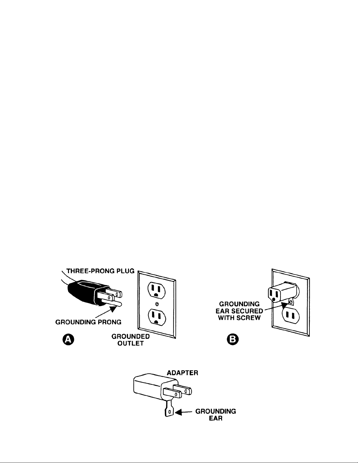
Grounding Instructions
Caution: This tool must be grounded while in use to protect the operator from electric shock.
In the event of a malf unc tion or breakdown, groundi ng pr ovides a path of least resistance for electric
current to r educ e the risk of electric shock. This tool is equipped with an elect ric cord having an
equipment -grounding conductor and a gr ounding plug. The plug must be plugged into a matc hing outlet
that is properly installed and grounded in accordance with all l oc al codes and ordinances.
Do not modi fy the pl ug pr ovided. If it will not fit the outlet, have the proper outlet inst alled by a qualified
electrician.
Improper connection of the equipment-grounding conduct or c an r esult in a risk of electr ic shock. The
conductor, with insulation having an outer surface that is green with or without yellow stripes, is the
equipment -grounding conductor. If repair or replacement of the electri c c ord or plug is necessary, do not
connect the equi pment-groundi ng c onduc tor to a li ve terminal.
Check with a qualified electric ian or service personnel if the grounding i nst r uc tions are not completely
understood, or if in doubt as to whether t he tool is properl y gr ounded. Use only three wire extension
cords that have three-prong grounding plugs and three-pole r ec eptacles that accept the tool’s plug.
Repair or replace a damaged or worn cord i mmediately.
115 Volt Operation
As received from the factory, your sander is ready to run at 115 volt operation. This sander, when wired
for 115 volt, is intended for use on a circuit that has an outlet and a plug that look s l ike the one illustrated
in (A). A temporary adapter, which looks l ike the adapter as illustrated in (B), may be used to connect
this plug to a two-pole receptacl e, as shown in (B) if a proper ly grounded outlet is not av ailable. The
temporary adapter should only be used until a properly gr ounded outlet can be i nstalled by a qualified
electrician. T his adapter is not applicable in Canada. The green colored rigid ear, lug, or tab,
extendi ng from the adapter, must be c onnected to a permanent ground such as a properly grounded
outlet box, as shown in (B).
5
Page 6

Specifications JSG-96
Stock Number................................................................................................................................ 708595
Sanding Belt............................................................................................................................ 6”W x 48”L
Disc Diameter.........................................................................................................................................9”
Table Tilt (down)..........................................................................................................................90° - 45°
Dust Chute Diameter..............................................................................................................................4”
Belt Table.......................................................................................................................... 5-1/2"W x 11"L
Disc Table............................................................................................................................. 10"W x 12”L
Motor.............................................................................................................3/4HP, 115V, 60Hz, 1Ph, 4P
Belt Speed (S FPM)...........................................................................................................................2,258
Disc Speed (RPM)............................................................................................................................1,725
Overall Dimensions..................................................................................................16"Lx29”Wx28-1/2”H
Net Weight (approx.) ....................................................................................................................128 Lbs.
Table of Contents
Warranty .................................................................................................................................................2
Warnings ....................................................................................................................... .......................3-4
Grounding Instructions.............................................................................................................................5
Specifications..........................................................................................................................................6
Table of Contents....................................................................................................................................6
Contents of the Shipping Carton..............................................................................................................7
Unpacking...............................................................................................................................................7
Stand Assembly ( optional)....................................................................................................................... 7
Assembly.................................................................................................................................................8
Sanding Belt Table Adj ustment ................................................................................................................9
Horizontal Sanding Workstop ................................................................................................................10
Sanding Belt Replacement ....................................................................................................................10
Belt Tracking Adjustment.......................................................................................................................11
Disc Table Adjustment......................................................................................................................11-12
Sanding Disc Replacement....................................................................................................................12
Center Point..........................................................................................................................................12
On/Off Switch........................................................................................................................................12
Dust Collection......................................................................................................................................13
Lubrication.............................................................................................................................................13
Optional Accessories.............................................................................................................................13
Troubleshooting.....................................................................................................................................14
Parts Breakdowns & Parts List..........................................................................................................15-24
The specif ications in this manual ar e given as general information and are not binding. JET Equipment
and Tools reserves the right to effec t, at any ti me and without prior notic e, changes or alterations to parts,
fittings, and accessory equipment deemed nec essary for any reason whatsoever.
6
Page 7
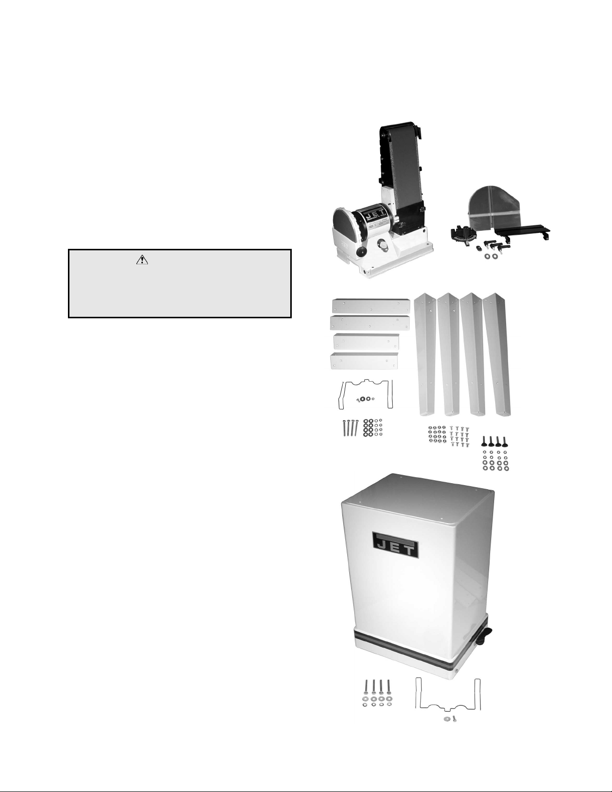
Contents of the Shipping Carton
1. Sander
1. Sanding Belt
1. Sanding Disc
2. Tables
1. Center Point
3. Handles
2. 5/16” Flat Washers
1. Miter Gauge
1. Owner's Manual
1. Warranty Card
Tools Required for Assembly
1. 13mm Wrench or socket (stand)
1. 12mm Wrench or socket (stand)
WARNING
Read and understand the entire contents of
this manu al before attemp t ing assembly or
operation of the disc/belt sander!
Failure t o comply may cause serious inj ury!
Unpacking
1. Remove all contents from the shipping
carton.
2. Report any damage to your distri butor.
3. Do not discard any shipping material until
the sander has been assembled and is
running properly.
Open Stand Assembly (Optional)
1. Match the hole patterns in the stand legs
with the hole patterns in the stand top
pieces. Mount the legs to the outside of the
top pieces using six teen 5/16”x 5/8” carri age
bolts and sixteen 5/16” lock nuts. Do not
tighten unt il the stand has been assembled
and is sitting level on the floor. Note:
Flange of long top pieces ov erlap f lange of
short top pieces.
2. Install the leveling pads in the bottom hole
of legs with eight 3/8” hex nuts and eight
3/8” flat washers.
3. Mount the belt r ack t o t he stand by i nserti ng
the 90° bend through t he stand and securing
the rack in place with a 3/8”x3/4” hex cap
bolt, t wo 3/8” flat washers and a 3/8” hex nut.
Closed Stand Assembly (Optional)
1. Mount the belt r ack t o t he stand by i nserti ng
the 90° bend through t he stand and securing
the rack in pl ace with a hex cap bolt, and a
flat washer.
7
Page 8
Assembly
CAUTION
Machine i s heavy! Use care when l ifting out
of the shipping carton and moving to a final
location. Stand or bench must be stable
enough to support weight of machine.
1. Move the sander t o a workbench or one of
JET’s optional stands. B olt the uni t f i rm l y t o
hold in pl ace.
JET’s closed stand uses four 3/8”x2-1/2”
hex cap bolts, four 3/8” lock washers and
four 3/8” flat washers provided with the
stand.
JET’s open stand uses four 3/8”x3” hex
cap bolts, f our 3/8” lock washers and eight
3/8” flat washers, and four hex nuts
provided with the stand.
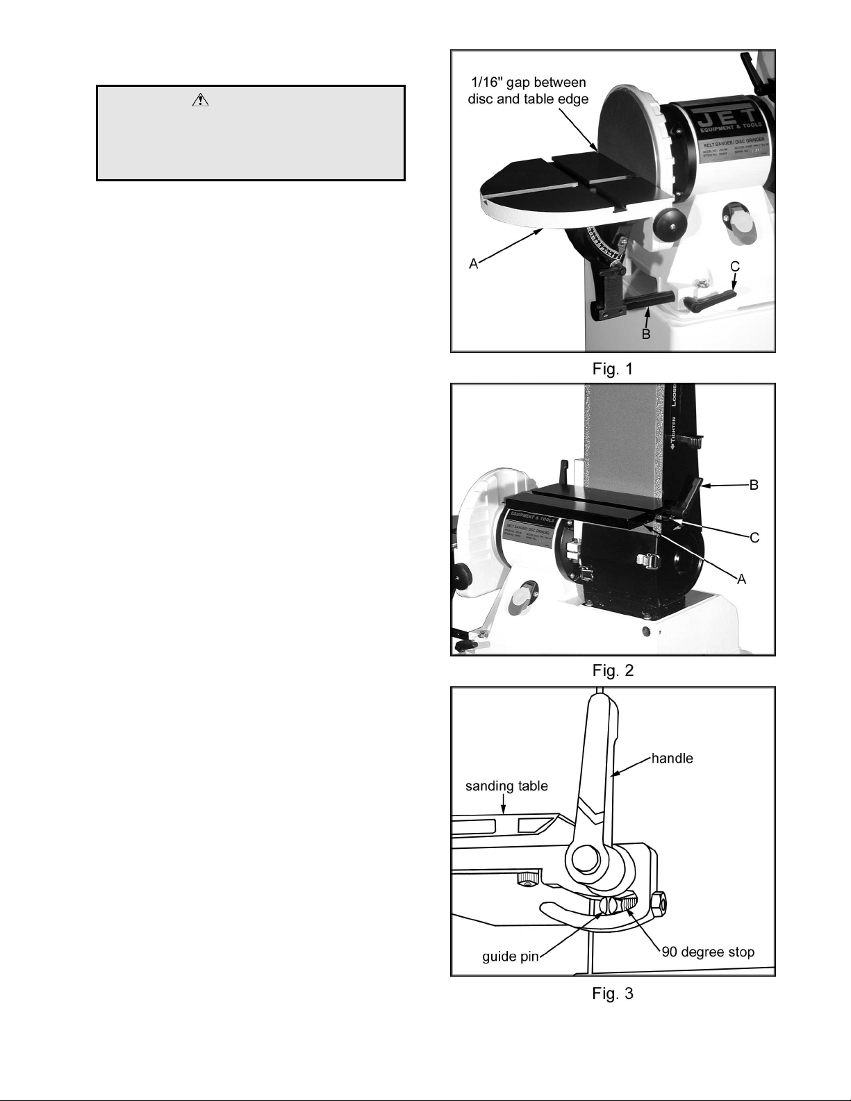
2. Mount the sanding disc table assembly (A,
Fig. 1) to the sander base. Insert the rod (B,
Fig. 1) into the base and secure in place
using the 5/16” handle (C, Fig. 1). The
handle should tighten against the flat portion
of the rod.
3. Mount the sanding belt table (A, Fig. 2) to
the sander with two 5/16”x1-1/4” locking
handles (B, Fig. 2), two 5/16” flat washers.
The handle stud needs to go through the
upper slot, and the guide pin (C, Fig. 2 &
Figure 3) l ocated on the sander should rest
in the lower slot.
Note: The bel t table can be removed and
the disc table can be used in its place.
There are two holes in the base, bel ow the
sanding belt, that will accommodate the disc
table’s support rod and l oc k ing handle.
8
Page 9

Sanding Belt Table Adjustment
WARNING
Always disconnect the sand er f rom the
power source before servici ng or making
any adjustments.
Failure t o comply may cause serious inj ury!
1. Place a square on the sanding belt table
with one edge along the graphite pad, or
sanding belt (Figure 4).
2. If the table is not square to the bel t adjust
the table by loosening the two locking
handles. Adjust t o the square position and
tighten handles.
3. Place a combination square (A, Fig. 5) in
the miter gauge slot (B, Fig. 5) and check
the distance from the slot to the edge of the
sanding belt. Slide the square al ong the slot
to the other end of the belt and check the
distance. The di stances should be equal t o
ensure that the mit er gauge travels paral lel
to the belt. Loosen the t wo socket head cap
screws at the bottom of the table, which
hold the table and left trunnion in place to
adjust the dist anc e.
4. Always maintain a gap of approximately
1/16” between the table edge and belt.
Once the tabl e is square and parallel to the
belt adjust the 90° stop. Loosen the hex nut
and tighten t he set scr ew until it contacts the
guide pin, ( Figure 6). Tight en the hex nut.
Repeat for the other side.
5. If you need to sand at a precise angle,
loosen the handles that secure the table in
place. Set a combination square on the
table and adjust to the desired angle.
Always maintain a gap of approximately
1/16” between the table edge and belt.
Note: The bel t table can be removed and
the disc table can be used in its place.
There are two holes in the base, bel ow the
sanding belt, that will accommodate the disc
table’s support rod and l oc k ing handle.
9
Page 10

Horizontal Sanding Workstop
1. Loosen the socket head cap screw (A, Fig. 7)
so that the sanding belt can be rotated to
the horizont al position.
2. Rotate the sander until the stop (B, Fi g. 7)
contacts the sander base. Tighten the
socket head cap screw.
3. When the sanding belt is used in the
horizontal position, the table may be used
as a workstop, as shown in Figure 7.
Sanding Belt Replacement
1. Disconn ect the machine from t he power
source.
2. Remove the handle (A, Fig. 8).
3. Release two latches (B, Fig. 8) and open the
doors.
4. Piv ot the trunnion assembly (A, Fig. 9) out
of the way.
5. Release the belt tension by moving the
tension handle to the “Loosen” position.
6. Slide t he belt off of bot h sandi ng dr ums.
7. Slide new 6”x48” bel t sanding bel t over bot h
sanding drums, making sure the belt will
travel in the direction of the arrow located
on the inside of the belt.
8. Re-appl y belt tension by m ov ing t he tension
handle to the “T ighten” position. See “Belt
Tracki ng A djustment”.
10
Page 11

Belt Tracking Adjustment
1. Connect the machine to the power source.
One time quickl y turn the m ac hine “ON” and
“OFF”. This will allow you to view the belts
tendency to run down the middle, to the
right, or to the left. The belt should run
centered on the sanding drums. Do not let
the belt run of f the drum to t he right, or lef t.
The belt will tear when it contacts parts of
the machine.
2. Disconnect the machine from the power
source. Move the tension handle ( A , Fig. 10)
to the “Loosen” position. Center the belt
again and mov e the handl e to the “Ti ghten”
position.
3. Release the tracking lock (B, Fig. 10) by
pulli ng up on the handle. If the beIt has a
tendency to track left of center, turn the
adjusting knob (C, F i g. 10) c ounterc loc kwise
until the belt trac k s i n the center.
4. If the belt has a tendency to track right of
center, turn the adjusting knob clockwise
until the belt trac k s i n the center.
5. Secure the tracking lock by pushing the
lever down. Note: when tightening the
tracking lock the belt may tend to move to
the left.
6. Fine tune tracking by turning the adjusting
knob (C, Fig. 10).
Note: To prevent the sanding belt from
stretching and to prolong belt life, remove the
belt tension from the sander if not using for a
long period of time.
Disc Table Adjustment
1. Disconnect machine from the power
source.
2. Place a square on the table next to the
sanding disc (Figure 11). Loosen locking
handle and mov e the table to 90° . Tighten
locking handles.
3. Place a combinati on square (A, Fig. 12) in
the mi ter gauge slot (B, F ig. 12) and check
the distance from the slot to the edge of the
sanding disc. Slide the square along the
slot to the ot her end of the di sc and check
the distance. The distances should be
equal to ensure that t he mi ter gauge trav el s
parallel to the disc.
11
Page 12

4. If the mit er slot i s not paral l el l oosen the t wo
socket head cap screws (A, Fig. 13) and
adjust for parallel. Tighten the two screws
when the adjustment is complete.
5. Always maintain a gap of approximately
1/16” between the table edge and disc.
Once the tabl e is square and parallel to the
disc adjust the 90° stop. Loosen hex nut (B ,
Fig. 13) and tighten the set screw (C, Fig.
13) until it contacts the trunnion. Tighten
hex nut.
6. If the pointer does not line up wit h the “0” on
the scale loosen the screw and adjust for “ 0”.
Tighten t he scr ew.
7. The table can be tilted between 0°-45° by
loosening the handl e (D, Fig. 13) and tilt ing
the table to the desi red angle. Tighten t he
handle. Always maintain a gap of
approxim atel y 1/16” bet ween the table edge
and disc.
Note: The bel t table can be removed and
the disc table can be used in its place.
There are two holes in the base below the
sanding belt that will accommodate the disc
table’s support rod and l oc k ing handle.
Sanding Disc Replacement
1. Disconnect machine from the power
source.
2. Loosen the handle (C, Fig. 14) and rem ove
the table assembly (A, Fig. 14).
3. Turn the knob (B, Fig. 14) and open the
door.
4. Remove old sanding disc by striping from
wheel. Make sure the di sc plate is clean.
5. Press the new disc fir mly into place.
Center Point
The center point (A, Fig. 15) prov ided with the
sander can be used for sanding circles. The
center point can be locked in position by
tightening the set screws (B, Fig. 15).
On/Off Switch
The machine can be turned on by moving the
switch (C, Fig. 15) to the up positi on. The key
(D, Fi g. 15) can be remov ed when the mac hine
is in the of f positi on. W it h the key rem ov ed the
switch will not operate.
12
Page 13

Dust Collection
1. Hook the sander to a dust col lector using a
4” diameter hose and clamp (A, Fig. 16).
JET of f ers a wide variety of hoses, adapt ers
and dust collec tors.
2. Loosen the wing nut (B, F ig. 16) and pull t he
gate (C, Fi g. 16) open to al l ow air suct i on t o
the sanding belt. Push the gate closed to
shut off air suction. Tighten the wi ng nut.
3. Push the gate (D, F ig. 16) down to shut of f
air sucti on to the di sc. Lif t the gate to open
the air suction to the disc.
Lubrication
All moving parts run on sealed ball bearings and
require no l ubr ication.
Optional Accessories
Open Stand w/Belt Rack 708596
Closed Stand w/Belt Rack708597
JET Stik Abrasive Belt and Di sc Cleaner 57620025
Dust Collect ors and Accessories see JET Distributor
JSG-96 Sanding Belts, Master Carton 10
6”x48” 24 Grit 40 Grit 60 Grit 80 Grit 100 Grit 120 Grit 150 Grit 180 Grit
Close
d Coat
Open
Coat
57617110 57617210 57617410 57617510 57617610 57617710
57432910 57422110 57422210 57422310 57422410 57422510
57512210 57512310
57422610 57422710
JSG-96 Sanding Disc PSA Aluminum Oxide Cloth Back Sanding Disc, Master Carton 25
9” 36 Grit 50 Grit 60 Grit 80 Grit 100 Grit 120 Grit
Close
d Coat
57697525 57697650 57697750 57697850 57697950 57698050
13
Page 14

Troubleshooting
Trouble Possible Cause Solution
1. Sander unplugged from wall
or motor
Sander will not start
Sanding belt does not come
up to speed
Machine vi brates excessively 1. Stand on uneven floor
Abrasive belt keep s t earing
2. Fuse blown or circuit breaker
tripped
3. Cord damaged
1. Extension cord too light or
too long
2. Low current
1. Belt i s running in the wrong
direction
1. Check all plug connections
2. Replace f use or r eset c ircuit
breaker
3. Replace cord
1. Replace with adequat e si z e
and length cord
2. Contact a qualifi ed
electrician
1. Adjust stand so that it rests
evenly on the floor
1. Arrow on the sanding belt
and machine should be
pointing in the same
direction.
Sanded edge not square
Sanding marks on wood
1. Table not square t o sandi ng
belt
2. Miter sl ot not parallel to
sanding belt
1. Work held still
2. Wr ong grit sanding belt
3. Feed pressure too great
4. Sanding against the grain
14
1. Use a square to adjust table
to sanding belt
2. Use a square to adjust the
table’s miter slot parallel to
the sanding belt.
1. Keep workpiece m oving
2. Use coarser grit for stock
removal and fine grit for
finish sanding.
3. Never force work into
sanding platen
4. Sand with the grain
Page 15

Disc Sander Assembly Breakdown
15
Page 16

Parts List For The JSG-96 Sa nder
Disc Sander Assembly
Index Part
No. No. Description Size Qty.
1..........JSG96-101....................... Base.............................................................. ...................................1
2..........JSG96-102....................... Motor............................................................. ...................................1
............ JSG96-102A .................... Starting Capacitor (not shown)....................... ...................................1
............ JSG96-102B .................... Running Capacit or ( not shown)...................... ...................................1
3..........TS-1550041 ..................... Flat Washer...................................................M6 ..............................4
4..........TS-1551041 ..................... Lock Washer ................................................. M6..............................7
5..........TS-1540041 ..................... Hex Nut ......................................................... M6..............................1
6..........JSG96-106....................... Disc Cover .................................................... ...................................1
7..........JSG96-107....................... Screw w/Washer............................................1/4x3/8.......................3
8..........JSG96-108....................... Air Controller................................................. ...................................1
9..........TS-0813032 ..................... Screw............................................................ 1/4x1/2 .......................2
10........ JSG96-110....................... Lock Knob..................................................... ...................................1
11........ JSG96-111....................... Tap Screw..................................................... 1/4x1..........................1
12........ JSG96-112....................... Key................................................................ 5x5x25 .......................1
13........ JSG96-113....................... Disc............................................................... ...................................1
14........ JSG96-114....................... Set Screw...................................................... #10x3/8 ......................1
15........ JSG96-115....................... Sandi ng Disc................................................. ...................................1
16........ JSG96-116....................... End Cover..................................................... ...................................1
17........ JSG96-117....................... Pin................................................................. ...................................1
18........ JSG96-118....................... Compound Table........................................... ...................................1
19........ JSG96-119....................... Table Bracket................................................ ...................................1
20........ JSG96-120....................... Trunnion........................................................ ...................................2
21........ JSG96-121....................... Pin................................................................. ...................................2
22........ JSG96-122....................... Hex Socket Cap Screw.................................. #10x5/8 ......................2
23........ JSG96-123....................... Table Support w/Scal e................................... ...................................1
24........ TS-0680031 ..................... Flat Washer*................................................. 5/16............................2
25........ TS-0051021 ..................... Hex Head Screw............................................5/16x5/8.....................2
26........ JSG96-126....................... Lock Handle*................................................. ...................................1
27........ JSG96-127....................... Screw............................................................ 1/4x3/8.......................7
28........ JSG96-128....................... Pointer........................................................... ...................................1
29........ TS-0270031 ..................... Set Screw......................................................5/16x3/8.....................2
30........ JSG96-130....................... Rod ............................................................... ...................................1
31........ JSG96-131....................... Set Screw...................................................... 1/4x1..........................1
32........ TS-0561011 ..................... Hex Nut ......................................................... 1/4..............................1
33........ JSG96-133....................... Lock Handle .................................................. 5/16x1........................1
34........ JSG96-134....................... Switch Plate.................................................. ...................................1
35........ JSG96-135....................... Switch ........................................................... ...................................1
............ JSG96-135A .................... Switch Key (not shown)................................. ...................................1
36........ JSG96-136....................... Plate.............................................................. ...................................1
37........ JSG96-137....................... Screw w/Flange............................................. #10x3/8 ....................17
38........ TS-0680011 ..................... Flat Washer...................................................3/16 ............................1
39........ JSG96-139....................... Strain Relief .................................................. ...................................1
40........ JSG96-140....................... Power Cord ................................................... ...................................1
41........ JSG96-141....................... Dust Chute.................................................... ...................................1
42........ JSG96-142....................... Circle Gauge*................................................ ...................................1
43........ JSG96-143....................... Tip................................................................. ...................................1
44........ JSG96-144....................... Set Screw...................................................... 1/4x1/4....................... 2
45........ JSG96-145....................... Set Screw...................................................... M4x6.......................... 1
46........ JWBS18-403.................... Miter Gauge Body ......................................... ...................................1
47........ JSG96-147....................... Guide Bar...................................................... ...................................1
48........ JWBS18-401.................... Lock Handle .................................................. ...................................1
49........ JWBS20-156.................... Guide Disc..................................................... ...................................1
50........ JSG96-150....................... Pan Head Screw............................................ 1/4x5/16.....................1
16
Page 17

Index Part
No. No. Description Size Qty.
51........ JSG96-151....................... Screw............................................................ #10x5/16 ....................1
52........ JWBS18-406.................... Pointer........................................................... ...................................1
53........ JSG96-153....................... Bushing......................................................... ...................................1
54........ JSG96-154....................... I.D. Label....................................................... ...................................1
55........ JSG96-155....................... Indication Label............................................. ...................................1
............ JSG96-MGA .................... Miter Gauge Assembly (It ems 38, 46 thru 52) ...................................1
............ JSG96-CGA..................... Circle Gauge Assembly (Items 42 thru 45)..... ...................................1
* item s marked with an asterisk ar e par t of the Hardware Ki t, page 20.
17
Page 18

Belt Sander Assembly Breakdown
18
Page 19

Belt Sande r Assembly
Index Part
No. No. Description Size Qty.
1..........JSG96-201....................... Bracket.......................................................... ...................................1
2..........TS-0208071 ..................... Hex Socket Cap Screw.................................. 5/16x1-1/4..................1
3..........JSG96-203....................... Pin................................................................. ...................................1
4..........JSG96-204....................... Fixed Plate.................................................... ...................................1
5..........TS-0680021 ..................... Flat Washer...................................................1/4..............................8
6..........JSG96-206....................... Screw............................................................ 1/4x3/8.......................3
7..........JSG96-207....................... Key................................................................ 5x5x70 .......................1
8..........JSG96-208....................... Drive Drum.................................................... ...................................1
9..........JSG96-209....................... Lock Nut ........................................................ 5/8-18UNF..................1
10........ JSG96-210....................... Belt Support .................................................. ...................................1
11........ JSG96-211....................... Hex Socket Cap Screw.................................. 5/16x5/8.....................4
12........ TS-0720081 ..................... Lock Washer ................................................. 5/16............................5
13........ TS-0680031 ..................... Flat Washer...................................................5/16 ............................6
14........ TS-0270031 ..................... Set Screw......................................................5/16x3/8.....................4
15........ JSG96-215....................... Bracket.......................................................... ...................................1
16........ TS-0208061 ..................... Hex Socket Cap Screw.................................. 5/16x1........................1
17........ TS-0561021 ..................... Hex Nut ......................................................... 5/16............................1
18........ JSG96-218....................... Rod ............................................................... ...................................1
19........ JSG96-219....................... Pad ............................................................... ...................................1
20........ JSG96-220....................... Set Screw...................................................... 1/4x3/8....................... 1
21........ JSG96-221....................... Follow Roller................................................. ...................................1
22........ BB-6201ZZ ...................... Ball Bearing................................................... ...................................2
23........ JSG96-223....................... C-Ring........................................................... STW-11......................2
24........ JSG96-224....................... Shaft ............................................................. ...................................1
25........ JSG96-225....................... Bushing......................................................... ...................................1
26........ TS-0680041 ..................... Flat Washer...................................................3/8..............................1
27........ JSG96-227....................... Lock Nut ........................................................ 3/8..............................1
28........ JSG96-228....................... Roll Pin .........................................................4x20...........................1
29........ JSG96-229....................... Support B r acket............................................. ...................................1
30........ JSG96-230....................... Micro-Adjusting Seat..................................... ...................................1
31........ TS-0207021 ..................... Hex Socket Cap Screw.................................. 1/4x1/2.......................6
32........ JSG96-232....................... Screw............................................................ ...................................1
33........ JSG96-233....................... Adjusting Knob.............................................. ...................................1
34........ JSG96-234....................... Spring............................................................ ...................................1
35........ JSG96-235....................... Lock Nut ........................................................ M6..............................1
36........ JSG96-236....................... Washer.......................................................... ...................................2
37........ JSG96-237....................... Disc Spring.................................................... ...................................2
38........ JSG96-238....................... Lock Handle .................................................. ...................................1
39........ JSG96-239....................... Roll Pin .........................................................3x20...........................1
40........ JSG96-240....................... Spring............................................................ ...................................1
41........ JSG96-241....................... Eccentric Handle........................................... ...................................1
42........ JSG96-242....................... Hex Socket Cap Screw.................................. 1/4x1-1/4....................1
43........ JSG96-243....................... Lock Nut ........................................................ 1/4..............................2
44........ JSG96-244....................... Air Controller (Belt)........................................ ...................................1
45........ JSG96-245....................... Dust Chute.................................................... ...................................1
46........ JSG96-246....................... Wing Screw................................................... 1/4x1/2.......................1
47........ JSG96-247....................... Flat Washer................................................... 1/4x3/4.......................3
48........ JSG96-248....................... Back Cover ................................................... ...................................1
49........ JSG96-249....................... Sandi ng B elt.................................................. ...................................1
50........ JSG96-250....................... Belt Table ...................................................... ...................................1
51........ JSG96-251....................... Trunnion........................................................ ...................................2
52........ TS-0050021 ..................... Hex Socket Cap Screw.................................. 1/4x5/8.......................2
53........ JSG96-253....................... Guide Pin...................................................... ...................................2
19
Page 20

Index Part
No. No. Description Size Qty.
54........ TS-0561011 ..................... Hex Nut ......................................................... 1/4..............................2
55........ JSG96-255....................... Set Screw...................................................... 1/4x3/4....................... 2
56........ JSG96-256....................... Lock Handle*................................................. 5/16x1-1/4..................2
57........ JSG96-257....................... Graphi te Pad................................................. ...................................1
58........ JSG96-155....................... Indication Label............................................. ...................................1
59........ JSG96-259....................... Loosen/T ighten Label .................................... ...................................1
60........ JSG96-260....................... Flat Washer................................................... 1/4x9/16x1/8...............2
61........ JSG96-261....................... Serrated Plate............................................... ...................................2
62........ JSG96-262....................... Phillips Tap Screw......................................... M3x10........................4
63........ JSG96-263....................... Lock Washer.................................................¼................................1
64........ JSG96-264....................... Set Screw...................................................... 1/4x1-1/2....................1
............ JSG96-HK........................ Hardware Kit (Includes it ems marked with *, and a 6mm hex wrench)
20
Page 21

Open Stand Breakdown
21
Page 22

JSG-96 Open Stand Assembly
Index Part
No. No. Description Size Qty.
1..........JSG96-401....................... Stand Top ( front and rear, short).................... ...................................2
2..........JSG96-402....................... Stand Top ( left and r ight, long) ...................... ...................................2
3..........JSG96-403....................... Stand Leg w/Tool Holder ............................... ...................................2
4..........JSG96-404....................... Stand Leg...................................................... ...................................2
5..........JSG96-405....................... Carriage Bolt*................................................5/16x5/8...................16
6..........JSG96-406....................... Lock Nut w/Flange*.......................................5/16..........................16
7..........JSG96-407....................... Leveling Pad*................................................ ...................................4
8..........TS-0561031 ..................... Hex Nut*........................................................3/8............................13
9..........TS-0680041 ..................... Flat Washer*................................................. 3/8............................17
10........ TS-0060131 ..................... Hex Head Screw*..........................................3/8x3..........................4
11........ JSG96-314....................... Tool Shelf ...................................................... ...................................1
12........ JSG96-316....................... Flat Washer*.................................................3/8x1-1/8....................1
13........ TS-0060031 ..................... Hex Head Screw*..........................................3/8x3/4.......................1
14........ TS-0720091 ..................... Lock Washer*................................................ 3/8..............................4
............ JSG96-HKA..................... Hardware Kit for Open Stand (includes items marked wit h *)
22
Page 23

Closed Stand Breakdown
23
Page 24

Closed Stand Assembly
Index Part
No. No. Description Size Qty.
1..........JSG96-301....................... Base.............................................................. ...................................1
2..........JSG96-302....................... Lock Nut ........................................................ 3/8..............................4
3..........PJE-S05........................... Wheel............................................................ ...................................4
4..........JSG96-304....................... Hex Head Screw* .......................................... 3/8x2-1/2....................8
5..........JSG96-305....................... Shaft ............................................................. ...................................1
6..........PJN-S04 .......................... Eccentric Cam............................................... ...................................2
7..........JSG96-307....................... Set Screw...................................................... M6x10........................2
8..........JSG96-308....................... Spring............................................................ ...................................2
9..........JSG96-309....................... Roll Pin .........................................................4x16...........................2
10........ PJN-S02 .......................... Foot Brake..................................................... ...................................1
11........ JSG96-311....................... Lock Nut ........................................................ M10x1.5 .....................1
12........ TS-0720091 ..................... Lock Washer*................................................ 3/8..............................4
13........ TS-0680041 ..................... Flat Washer*................................................. 3/8..............................4
14........ JSG96-314....................... Tool Shelf ...................................................... ...................................1
15........ TS-0060031 ..................... Hex Head Screw*..........................................3/8x3/4.......................1
16........ JSG96-316....................... Washer*........................................................3/8x1-1/8....................1
17........ JSG96-317....................... JET Plaque.................................................... ...................................1
18........ JSG96-318....................... Door.............................................................. ...................................1
19........ JSG96-319....................... Latch............................................................. ...................................1
20........ JSG96-320....................... Screw............................................................ M3..............................2
21........ JSG96-321....................... Door Pivot..................................................... ...................................1
22........ JSG96-127....................... Screw............................................................ 1/4x3/8.......................2
23........ TS-0561011 ..................... Hex Nut ......................................................... 1/4..............................2
............ JSG96-HKB..................... Hardware Kit for Closed Stand (includes items mar k ed wi th *)
WMH Tool Group
2420 Vantage Drive
Elgin, Il l inois 60123
Phone: 800-274-6848
www.wmhtoolgroup.com
24
 Loading...