


F 1 8 F18 DP
F-18 / F-18DP INSTALLATION
This dishwasher must be installed on a level, rigid, nonflammable surface. Ensure that the machine is level by installing
the feet (shipped in the wash tank of the machine) and adjusting the leveling. Be sure to provide adequate space for water, drain and electrical connections.
WATER SUPPLY
A 1/2" -140°F (60°C) hot water line with 30 PSI flow pressure and shut-off valve is required. A pressure reducing valve* may be required. A 1/2" flexible supply hose* is recommended from the shut-off valve to the water fill valve on the dishwasher to facilitate maintenance and servicing of the machine. A 90° elbow adapter for the water inlet valve is furnished with the machine and can be found in the wash tank with the adjustable feet. There should be sufficient hose length to permit the machine to be pulled out for service.
DRAIN
• F-18: This dishwasher has a gravity drain. Maximum height of the floor drain should not exceed 6" (15cm). A 1.5" ED flexible drain hose* is recommended to facilitate maintenance and servicing of the machine.
•F-18 DP: This dishwasher is equipped with an automatic drain pump that will pump the drain water to a maximum height of 36" (0.9 meter). A 1" ED flexible drain hose* is recommended to facilitate maintenance and servicing of the machine. It is important not to reduce the size of this hose. A 1" check-valve* is required on drain pump equipped models. Drain pump equipped machines have a white button on the control panel beside the green power button.
DRAIN PUMP MODELS ARE FACTORY BUILT. GRAVITY DRAIN UNITS CANNOT BE CONVERTED TO PUMPED DRAIN UNITS. There should be sufficient hose length to permit the machine to be pulled out for service.
ELECTRICAL
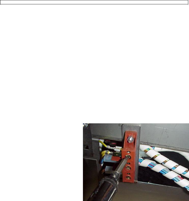
A 208-240 volt, 60 Hz, Single Phase circuit is required for this unit. Check the rating plate on the machine for amp draw. In spite of the fact that the rating plate shows 208 volts, the unit is designed function properly on 208 volts to 240 volts. The top & back panels must be removed for the electrical hook-up. The terminal block is located inside the back cover. Pass the cable through the cable strain relief and connect the wires to the terminals LI (brown wire), L2 (blue wire) & Ground (yellow & green wire). Replace the top & back panels being careful not to pinch or kink any wires or hoses. There should be sufficient cable length to permit the machine to be pulled out for service. DO NOT
TURN ON THE POWER TO THE MACHINE UNTIL THE WATER SUPPLY & DRAIN LINES HAVE BEEN CONNECTED.
IMPORTANT NOTE
Reasonable access to and around the machine for service must be provided. Disconnecting of hard plumbing or removal of counter tops or cabinets, etc.. for servicing is not covered by warranty.
* - not supplied

F-18 ELECTRICAL DIAGRAM
 Loading...