


This .pdf document is bookmarked
Operating Instructions and Parts Manual
14-inch Deluxe Pro Band Saw
Models: JWBS-14DXPRO
(Shown with optional Rip Fence)
JET
427 New Sanford Road
LaVergne, Tennessee 37086 Part No. M-710116
Ph.: 800-274-6848 Revision D1 09/2018
www.jettools.com Copyright © 2017 JET

Warranty and Service
JET® warrants every product it sells against manufacturers’ defects. If one of our tools needs service or repair, please contact
Technical Service by calling 1-800-274-6846, 8AM to 5PM CST, Monday through Friday.
Warranty Period
The general warranty lasts for the time period specified in the literature included with your product or on the official JET
branded website.
• JET products carry a limited warranty which varies in duration based upon the product. (See chart below)
• Accessories carry a limited warranty of one year from the date of receipt.
• Consumable items are defined as expendable parts or accessories expected to become inoperable within a
reasonable amount of use and are covered by a 90 day limited warranty against manufacturer’s defects.
Who is Covered
This warranty covers only the initial purchaser of the product from the date of delivery.
What is Covered
This warranty covers any defects in workmanship or materials subject to the limitations stated below. This warranty does not
cover failures due directly or indirectly to misuse, abuse, negligence or accidents, normal wear-and-tear, improper repair,
alterations or lack of maintenance. JET woodworking machinery is designed to be used with Wood. Use of these machines in
the processing of metal, plastics, or other materials may void the warranty. The exceptions are acrylics and other natural items
that are made specifically for wood turning.
Warranty Limitations
Woodworking products with a Five Year Warranty that are used for commercial or industrial purposes default to a Two Year
Warranty. Please contact Technical Service at 1-800-274-6846 for further clarification.
How to Get Technical Support
Please contact Technical Service by calling 1-800-274-6846. Please note that you will be asked to provide proof of initial
purchase when calling. If a product requires further inspection, the Technical Service representative will explain and assist
with any additional action needed. JET has Authorized Service Centers located throughout the United States. For the name of
an Authorized Service Center in your area call 1-800-274-6846 or use the Service Center Locator on the JET website.
More Information
JET is constantly adding new products. For complete, up-to-date product information, check with your local distributor or visit
the JET website.
How State Law Applies
This warranty gives you specific legal rights, subject to applicable state law.
Limitations on This Warranty
JET LIMITS ALL IMPLIED WARRANTIES TO THE PERIOD OF THE LIMITED WARRANTY FOR EACH PRODUCT.
EXCEPT AS STATED HEREIN, ANY IMPLIED WARRANTIES OF MERCHANTABILITY AND FITNESS FOR A PARTICULAR
PURPOSE ARE EXCLUDED. SOME STATES DO NOT ALLOW LIMITATIONS ON HOW LONG AN IMPLIED WARRANTY
LASTS, SO THE ABOVE LIMITATION MAY NOT APPLY TO YOU.
JET SHALL IN NO EVENT BE LIABLE FOR DEATH, INJURIES TO PERSONS OR PROPERTY, OR FOR INCIDENTAL,
CONTINGENT, SPECIAL, OR CONSEQUENTIAL DAMAGES ARISING FROM THE USE OF OUR PRODUCTS. SOME
STATES DO NOT ALLOW THE EXCLUSION OR LIMITATION OF INCIDENTAL OR CONSEQUENTIAL DAMAGES, SO THE
ABOVE LIMITATION OR EXCLUSION MAY NOT APPLY TO YOU.
JET sells through distributors only. The specifications listed in JET printed materials and on official JET website are given as
general information and are not binding. JET reserves the right to effect at any time, without prior notice, those alterations to
parts, fittings, and accessory equipment which they may deem necessary for any reason whatsoever. JET
are not sold in Canada by JPW Industries, Inc.
Product Listing with Warranty Period
90 Days – Parts; Consumable items
1 Year – Motors; Machine Accessories
2 Year – Metalworking Machinery; Electric Hoists, Electric Hoist Accessories; Woodworking Machinery used
for industrial or commercial purposes
5 Year – Woodworking Machinery
Limited Lifetime – JET Parallel clamps; VOLT Series Electric Hoists; Manual Hoists; Manual Hoist
Accessories; Shop Tools; Warehouse & Dock products; Hand Tools; Air Tools
NOTE: JET is a division of JPW Industries, Inc. References in this document to JET also apply to JPW Industries, Inc., or any
of its successors in interest to the JET brand.
®
branded products
2

Table of Contents
Warranty and Service .................................................................................................................................................2
Table of Contents .......................................................................................................................................................3
IMPORTANT SAFETY INSTRUCTIONS ...................................................................................................................4
Shipping Contents ......................................................................................................................................................7
Contents of Shipping Containers ............................................................................................................................7
Container Two .........................................................................................................................................................7
Tools Required for Assembly ..................................................................................................................................7
Fasteners for JWBS-14DXPRO ..............................................................................................................................7
Assembly ....................................................................................................................................................................8
Unpacking and Cleanup ..........................................................................................................................................8
Stand .......................................................................................................................................................................8
Mounting the Trunnion Bracket to the Band Saw ...................................................................................................9
Mounting the Table to the Bandsaw .......................................................................................................................9
Grounding Instructions............................................................................................................................................. 10
115 Volt Operation ............................................................................................................................................... 10
230 Volt Conversion ............................................................................................................................................. 10
Extension Cords ................................................................................................................................................... 11
Adjustments ............................................................................................................................................................. 12
Tilting the Table .................................................................................................................................................... 12
Adjusting 90° Table Stop ..................................................................................................................................... 12
Changing Blades .................................................................................................................................................. 13
Adjusting Blade Tension ...................................................................................................................................... 14
Adjusting Blade Tracking ..................................................................................................................................... 15
Adjusting Upper Blade Guide Assembly .............................................................................................................. 15
Adjusting Upper Blade Guides and Thrust Bearings ........................................................................................... 16
Adjusting Lower Blade Guides and Thrust Bearings ........................................................................................... 16
Adjusting Guide Post Parallel To Blade ............................................................................................................... 17
Changing Blade Speeds ...................................................................................................................................... 17
Optional Accessories ............................................................................................................................................... 18
Troubleshooting ....................................................................................................................................................... 18
Parts ........................................................................................................................................................................ 18
Body Assembly (JWBS-14DXPRO) ..................................................................................................................... 19
Body Assembly (JWBS-14DXPRO) ..................................................................................................................... 20
Closed Stand Assembly (JWBS-14DXPRO) ....................................................................................................... 24
Closed Stand Assembly (JWBS14-DXPRO) ....................................................................................................... 25
Electrical Schem atic – 115V ................................................................................................................................ 26
Electrical Schem atic – 230V ................................................................................................................................ 27
3

IMPORTANT SAFETY
INSTRUCTIONS
WARNING – To reduce the risk of injury:
1. Read and understand the entir e owner’s m anual
before attempting assembly or operation.
2. Read and understand the warnings posted on
the machine and in this manual. Failure to
comply with all of these warnings may cause
serious injury.
3. Replace the warning labels if they become
obscured or removed.
4. This band saw is designed and inte nded for use
by properly trained and experienced personnel
only. If you are not fam iliar with the proper and
safe operation of a band saw, do not use until
proper training and knowledge have been
obtained.
5. Do not use this band saw for other than its
intended use. If used for other purposes, JET
disclaims an y real or implied warr anty and holds
itself harmless from any injury that may result
from that use.
6. Always wear approved safety glasses/face
shields while using this band saw. Everyday
eyeglasses only have impact resistant lenses;
they are not safety glasses.
7. Before operating this band saw, remove tie,
rings, watches and other jewelry, and roll
sleeves up past the elbows. Remove all loose
clothing and confine lon g hair. Non-sl ip footwear
or anti-skid floor strips are recommended. Do
not wear gloves.
8. Always use the blade guard on all ''through-
sawing'' operations. A thro ugh-sawing operation
is one in which the blade cuts completely
through the workpiece.
9. Do not operate t his m achine while tired or under
the influence of drugs, alcohol or any
medication.
10. Make certain the switch is in the OFF position
before connecting the machine to the power
supply.
11. Make certain the machine is properly grounded.
12. Make all machine adjustments or maintenance
with the machine unplugged from the power
source.
13. Remove adjusting keys and wrenches. Form a
habit of checking to see that keys and adj usting
wrenches are rem oved from the mac hine before
turning it on.
14. Keep safety guards in place at all times when
the machine is in use. If removed for
maintenance purposes, use extreme caution
and replace the guards immediately.
15. Mak e sure the band s aw is firm ly secured to the
floor or bench before use.
16. Check damaged parts. Bef ore further use of the
machine, a guard or ot her part that is damaged
should be carefull y checked to determine th at it
will operate properly and perform its intended
function. Check for alignment of moving parts,
binding of moving parts, breakage of parts,
mounting and any other conditions that may
affect its operation. A guar d or other part that is
damaged should be properly repaired or
replaced.
17. Provide for adequate space surrounding work
area and non-glare, overhead lighting.
18. Keep the floor around the machine clean and
free of scrap material, oil and grease.
19. Keep visitors a safe distance from the work
area. Keep children away.
20. Make your workshop child proof with padlocks,
master switches or by removing starter keys.
21. Give your work undivided attention. Looking
around, carrying on a conversation and “horseplay” are careless acts that can r esult in serio us
injury.
22. Maintain a ba lanced stance at all times so th at
you do not fall into the blade or other moving
parts. Do not overreach or use excessive force
to perform any machine operation.
23. Us e the right tool at the cor rect speed and feed
rate. Do not force a tool o r attachment to do a
job for which it was not designed. The right to ol
will do the job better and safer.
24. Use recommended accessories; improper
accessories may be hazardous.
25. Maintain too ls with care. Keep s aw blades sharp
and clean for the best and safest performance.
Follow instructions for lubricating and changing
accessories.
26. Make s ure the work piece is held firm ly against
the rip fence or miter gaug e as it is fed through
the blade.
27. Turn off the machine before cleaning. Use a
brush or compressed air to remove chips or
debris — do not use your hands.
4

28. Do not stand on the machine. Serious injury
could occur if the machine tips over.
29. Never leave the machine running unattended.
Turn the power off and do not l ea ve the machine
until it comes to a complete stop.
30. Remove loose items and unnecessary work
pieces from the area before starting the
machine.
WARNING: This product can expose you to
chemicals including lead which is known to the
State of California to cause cancer and birth
defects or other reproductive harm. For more
information go to http://www.p65warnings.ca.gov.
WARNING: Drilling, sawing, sanding or
machining wood products gener at es woo d dust
and other substances known to the State of
California to cause cancer. Avoid inhaling dust
generated from wood products or use a dust
mask or other safeguards for personal protection.
Wood products emit chemicals known to the
State of California to cause birth defects or other
reproductive harm. For more information go to
http://www.p65warnings.ca.gov/wood.
Familiarize yourself with the following safety notices used in this manual:
This means that if precautions are not heeded, it may result in minor injury and/or possible
machine damage.
This means that if precautions are not heeded, it may result in serious injury or possibly even
death.
5

Specifications
Stock Number ................................................................................................................................................ 710116K
Model Number .................................................................................................................................... JWBS-14DXPro
Cutting Capacity (height) ........................................................................................................................................ 12”
Cutting Capacity (width) ................................................................................................................................... 13-1/2”
Minimum Blade Width ............................................................................................................................................ 1/8”
Maximum Blade Width ........................................................................................................................................... 3/4”
Blade Length ......................................................................................................................................................... 105”
Blade Speed .................................................................................................................................. 1500 / 3000 SFPM
Table Size ...................................................................................................................................................... 15” x 15”
Table Slot Size ....................................................................................................................................... 3/8”D x 3/4”W
Table Height from Floor .................................................................................................................................... 43-1/2”
Table Tilt (L-R) ............................................................................................................................................. 45°R / 10°
Dust Chute Diameter ........................................................................................................................................ 4” O.D.
Overall Dimensions (without fence) .............................................................................................. 77”H x 28”W x 29”D
Footprint Dimensions ............................................................................................................................... 17”W x 24”D
Motor ........................................................................................................... 1.25 HP, 1Ph, 115/230V (prewired 115V)
Net Weight (approx.).......................................................................................................................................... 247 lb.
Shipping Weight (approx.) ................................................................................................................................. 258 lb.
The specifications in this manual are g iven as general information and are not binding. JET reserves the right to
effect, at any time and without prior notice, alterations to parts, fittings, and accessory equipment deemed
necessary for any reason whatsoever.
6
Shipping Contents
Open both shipping containers and check for shipping
damage. Report any damage immediately to your
distributor and shipping agent. Read the instruction
manual thoroughly for assembly, maintenance and
safety instructions.
Contents of Shipping Containers
Container One
1 Stand
1 Door
2 Stand Supports
1 Accessory Package
Container Two
1 Saw body w/ motor
1 Poly-V Belt
1 Trunnion support bracket
1 Table
2 Table lock knobs
1 Table pin
1 Table insert
1 Fastener package (see fastener page)
1 Instruction manual
1 Warranty card
Tools Required for Assembly
(2) 10mm and (2)13mm open end wrenches or
adjustable wrenches
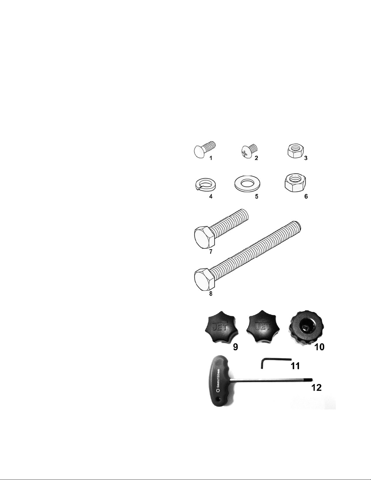
Fasteners for JWBS-14DXPRO
1 – M6x16 carriage bolt (4)
2 – M6x8 pan head screw (1)
3 – M6 hex nut (4)
4 – M8 lock washer (6)
5 – M8 flat washer (8)
6 – M8 hex nut(5)
7 – M8x40 hex cap screw (6)
8 – M8x80 hex cap screw (1)
9 – Lock Knob (2)
10 – Knob (1)
11 – 4mm hex wrench(1)
12 – 6mm T-handle hex wrench (1)
7

Assembly
Read and understand all
assembly instructions before attempting assembly!
Failure to comply may cause serious injury!
Unpacking and Cleanup
1. Finish removing all contents from the shipping
carton. Do not discard the carton or packing
material until the ba nd saw is assembled and
is running satisfactorily.
2. Inspect the contents for shipping damage.
Report damage, if any, to your distributor.
3. Compare the contents of the shipping carton
with the contents list in this manual. Report
shortages, if any, to your distributor.
Stand
Attach stand supports to back of cabinet BEFORE
placing saw body on top of cabinet.
1. Using four M 6x 16 c arr iage bolts ( C, F ig. 1) an d
four M6 nuts (B, Fig. 1) attach the stand
supports (A, Fig. 1) through the saw cabinet.
The bolt must be attached from the inside
bottom of the saw cabinet (fig 1). To do this it
is easiest if you ti lt the saw cabinet o n its front
and then install the hardware.
2. Place cabin et stand upr ight on a le ve l surf ace.
If the surface is une ven then you should le vel
the stand supports b y loos ening t he nut ( B, F ig
1) and moving the support up or down to
prevent the stand from rocking, then tighten
the nuts.
Saw body is heavy! Use caution
when lifting and stabilize until firmly attached to the
stand! Failure to comply may cause serious injury!
3. With the aid of a second person, lift the saw
body out of the shipping container and place
onto stand top. Be sur e front of saw (with J ET
logo) faces stand front (Door Side).
4. Line up holes in saw body with holes in the top
of the stand. Fasten saw body to the stand
with four M8 x 40 hex cap screws, eight M8
washers, four M8 lock washers, and four M8
hex nuts.
Figure 1
8
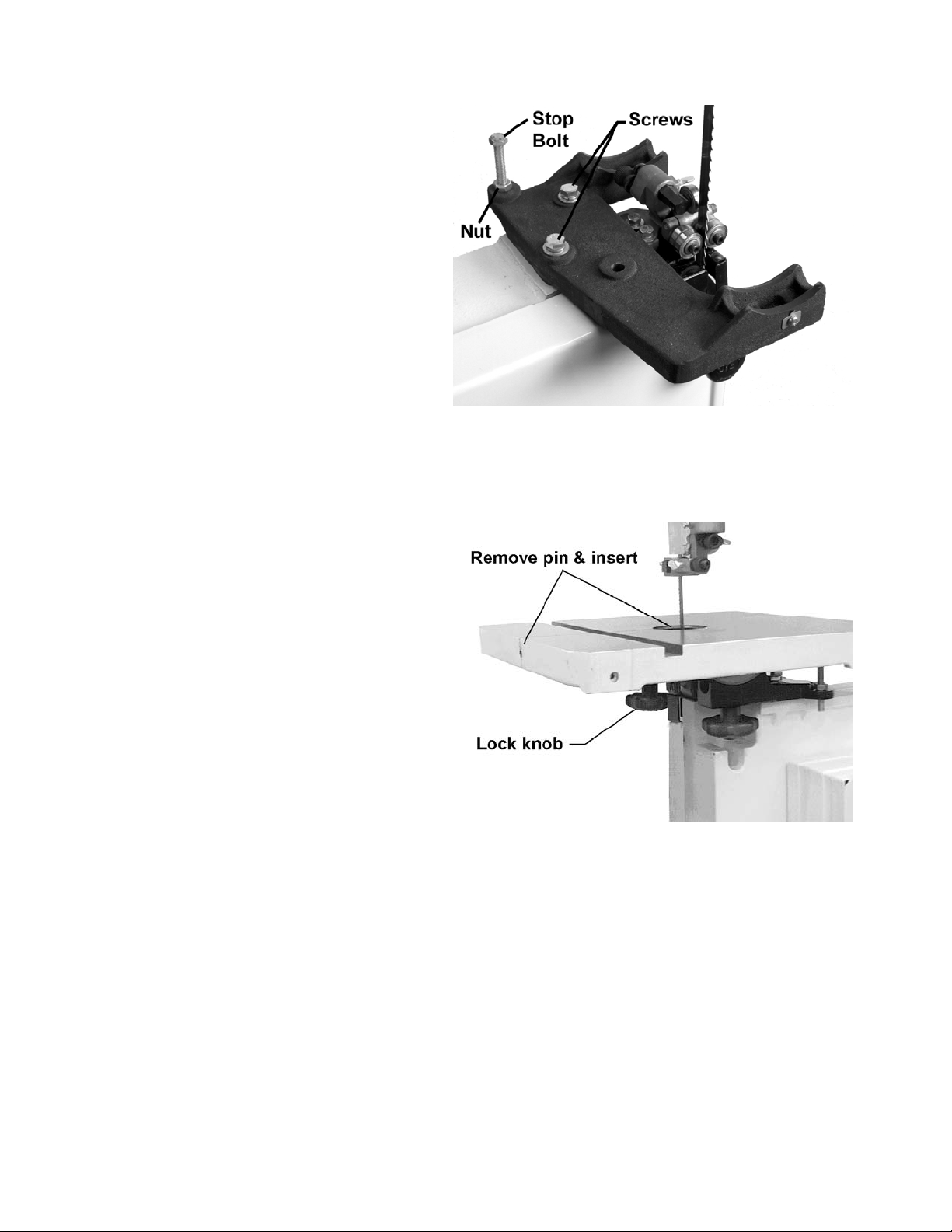
Mounting the Trunnion Bracket to the Band Saw
1. Attach trunnion support to saw body with two
M8 x 40 hex cap screws and two M8 lock
washers. See Figure 2.
2. Thread nut on to table stop bolt (Fig. 2) and
attach to trunnion support bracket as shown.
Once table is mounted to the trunnion bracket (see
section below) and the blade is mounted in the
saw (see section “Changing Blades”) you may
choose to fine tune the blade parallel to the miter
slot. Using a square positioned in the miter slot,
loosen screws shown in Figure 2 and lightly tap the
table into position so the blade is parallel with the
miter slot. Then gently tighten down the screws.
This adjustment will ensure square cuts when
using a miter gauge. This adjustment will NOT
correct drift of a blade when ripping with a rip
fence.
Figure 2
Mounting the Table to the Bandsaw
1. To m ount the t able, r emove pin and insert from
the table (Fig. 3).
2. Rotate the tab le so that the saw blade wil l sli de
through the slot in the table. Then orient the
table so the screws will sl ide into the holes on
the trunnion support bracket. Attach lock knobs
to these screws (Fig. 3)
3. Replace pin and insert.
Figure 3
9
 Loading...