


Warranty & Service
WMH Tool Group warrants every product it sells. If one of our tools needs service or repair, one of
our Authorized Repair Stations located throughout the United States can give you quick service.
In most cases, any one of these WMH Tool Group Repair Stations can authorize warranty repair,
assist you in obtaining parts, or perform routine maintenance and major repair on your JET,
Performax, Powermatic or Wilton tools.
For the name of an Authorized Repair Station in your area, call 1-800-274-6848.
More Information
WMH Tool Group is consistently adding new products to the line. For complete, up-to-date product
information, check with your local WMH Tool Group distributor or visit wmhtoolgroup.com.
Limited Warranty
WMH Tool Group (including JET, Performax, Powermatic and Wilton brands) makes every effort to
assure that its products meet high quality and durability standards and warrants to the original retail
consumer/purchaser of our products that each product be free from defects in materials and
workmanship as follows: 1 YEAR LIMITED WARRANTY ON ALL PRODUCTS UNLESS
SPECIFIED OTHERWISE. This warranty does not apply to defects due directly or indirectly to
misuse, abuse, negligence or accidents, normal wear-and-tear, repair or alterations outside our
facilities, or to a lack of maintenance.
WMH TOOL GROUP LIMITS ALL IMPLIED WARRANTIES TO THE PERIOD SPECIFIED ABOVE,
FROM THE DATE THE PRODUCT WAS PURCHASED AT RETAIL. EXCEPT AS STATED
HEREIN, ANY IMPLIED WARRANTIES OR MERCHANTIBILITY AND FITNESS ARE EXCLUDED.
SOME STATES DO NOT ALLOW LIMITATIONS ON HOW LONG THE IMPLIED WARRANTY
LASTS, SO THE ABOVE LIMITATION MAY NOT APPLY TO YOU. WMH TOOL GROUP SHALL IN
NO EVENT BE LIABLE FOR DEATH, INJURIES TO PERSONS OR PROPERTY, OR FOR
INCIDENTAL, CONTINGENT, SPECIAL, OR CONSEQUENTIAL DAMAGES ARISING FROM
THE USE OF OUR PRODUCTS. SOME STATES DO NOT ALLOW THE EXCLUSION OR
LIMITATION OF INCIDENTAL OR CONSEQUENTIAL DAMAGES, SO THE ABOVE LIMITATION
OR EXCLUSION MAY NOT APPLY TO YOU.
To take advantage of this warranty, the product or part must be returned for examination, postage
prepaid, to an Authorized Repair Station designated by our office. Proof of purchase date and an
explanation of the complaint must accompany the merchandise. If our inspection discloses a
defect, WMH Tool Group will either repair or replace the product, or refund the purchase price if we
cannot readily and quickly provide a repair or replacement, if you are willing to accept a refund.
WMH Tool Group will return repaired product or replacement at our expense, but if it is determined
there is no defect, or that the defect resulted from causes not within the scope of our warranty, then
the user must bear the cost of storing and returning the product. This warranty gives you specific
legal rights; you may also have other rights, which vary from state to state.
WMH Tool Group sells through distributors only. WMH Tool Group reserves the right to effect at any
time, without prior notice, those alterations to parts, fittings, and accessory equipment which they
may deem necessary for any reason whatsoever.
2

Specifications JVM-836
Stock Number ......................................................................................................690036 JVM-836-1
Stock Number ......................................................................................................690038 JVM-836-3
Spindle Taper................................................................................................................................R-8
Diameter of Quill (in).................................................................................................................. 3-3/8
Number of Spindle Speeds ......................................................................................... (5) JVM-836-1
Number of Spindle Speeds ....................................................................................... (10) JVM-836-3
Range of Spindle Speeds (rpm).......................................................................240-1,550 JVM-836-1
Range of Spindle Speeds (rpm).......................................................................120-1,550 JVM-836-3
Spindle Travel (in) .............................................................................................................................5
Collet Capacity (in) ................................................................................................................. 1/8-7/8
Head Movement ..............................................................................................................90° L and R
Maximum Travel of Ram (in) ................................................................................................... 10-1/2
Maximum Distance Spindle to Table (in) ................................................................................. 13-3/4
Minimum Distance Spindle to Column (in) ................................................................................ 5-1/4
Maximum Distance Spindle to Column (in) ............................................................................. 15-3/4
Maximum Longitudinal Table Travel (in).........................................................................................24
Maximum Cross Table Travel (in) .............................................................................................. 9-1/2
Maximum Knee Table Travel (in)....................................................................................................14
Size of Table (in) .................................................................................................................7-7/8 x 36
T-Slot (number) Size (in) ......................................................................................................... (3) 5/8
T-Slot Centers (in)...................................................................................................................... 2-1/2
Motor (JVM-836-1)....................................................................................... 1-1/2 HP, 1Ph 115/230V
.....................................................................................................................................prewired 115V
Motor (JVM-836-3)......................................................................................... 1-1/2 HP, 3Ph 2 Speed
...........................................................................................................................................230V Only
Floor Space Required (LxWxH/in) ..................................................................................55 x 52 x 77
Net Weight (approx.)...........................................................................................................1474 Lbs.
Table of Contents Page
Warranty ...........................................................................................................................................2
Specifications....................................................................................................................................3
Table of Contents..............................................................................................................................3
Installation Layout.............................................................................................................................4
Shipping Container Contents............................................................................................................5
Unpacking and Clean-Up .................................................................................................................5
Rotating the Head.............................................................................................................................5
Site Preparation................................................................................................................................6
Lifting the Mill....................................................................................................................................6
Lubrication ........................................................................................................................................7
Electrical Connections ......................................................................................................................7
Controls ........................................................................................................................................ 8-9
Changing Speeds .............................................................................................................................9
Position of Ram ................................................................................................................................9
Adjustments ....................................................................................................................................10
Parts Lists and Breakdowns ......................................................................................................11-22
Wiring Diagram ...............................................................................................................................23
The specifications in this manual are given as general information and are not binding. JET Equipment
& Tools reserves the right to effect, at any time and without prior notice, changes or alterations to parts,
fittings, and accessory equipment deemed necessary for any reason whatsoever.
3
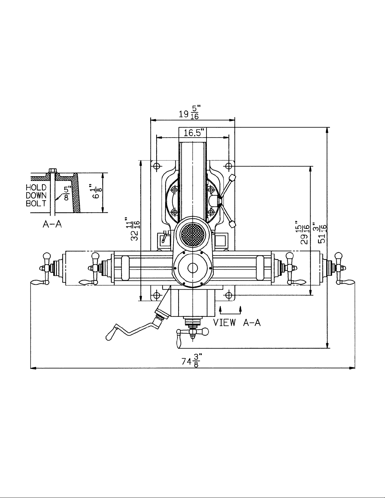
JVM-836 Installation Layout
4
Shipping Container Contents
1. Mill
1. Flat Way Cover (rear)
1. Accordion Way Cover (front)
1. Knee Crank
1. Drawbar
1. Tool Box:
1. Hex Wrench Set (1.5 - 10mm)
1. 17/19mm Combination Wrench
1. #2 Cross Point Screw Driver
1. #2 Flat Blade Screw Driver
1. Oil Can
1. Handwheel
1. Adjustable Wrench
5. Handles for Handwheels
1. Operator's Manual
1. Warranty Card
Unpacking and Clean-Up
1. Finish removing the sides and top of the
crate. Leave the mill bolted to the skid until
it is ready to be moved to its final location.
2. Clean all rust protected surfaces with
kerosene or a light solvent. Do not use
gasoline, paint thinner, or lacquer thinner.
These will damage painted surfaces.
3. Cover all machined surfaces with a film of
light machine tool oil to inhibit rust.
4. Remove wood block from below the knee.
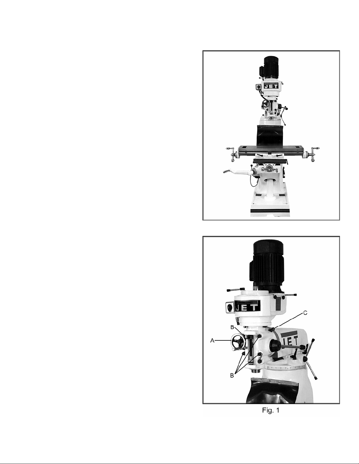
Rotating the Head
1. Remove handwheel (A, Fig. 1).
2. Loosen four cap nuts (B, Fig.1) with a ½
turn to unlock the head. Do not remove
these nuts unless you are prepared to
remove the head.
3. Use a 19mm socket and breaker bar on
adjusting nut (C, Fig. 1) to rotate the head.
5
Site Preparation
CAUTION!
Mill must be supported equally under all
four corners. Failure to comply may cause
the column to twist and put a bind in the
bedways.
The mill must be placed on an even surface
and bolted to the floor. Anchor bolts of
sufficient size and length must be fastened to
the floor according to the footprint of the mill.
See Installation Layout page 4.
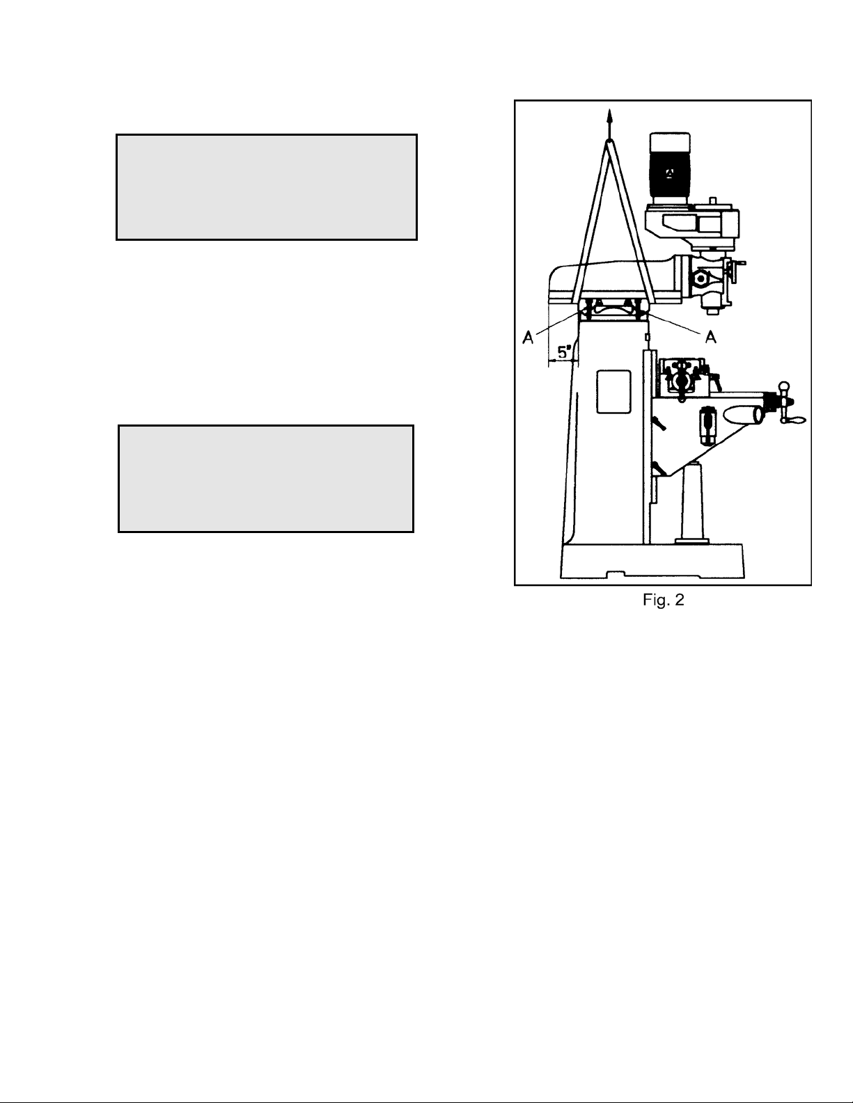
Lifting the Mill
,WARNING
Keep people a safe distance away from the
milling machine while it is being moved.
Failure to comply may cause serious
injury!
Lift the mill with appropriate sized lifting
straps. Follow the diagram in Fig. 2 for the
proper position of the straps under the ram.
Note: the position of the ram, and that the
table has been moved against the column.
Tighten ram locking bolts (A, Fig. 2) before
lifting.
Carefully lift the mill. Move into position over
the anchor bolts. Lower the mill onto the
anchor bolts. Check for level, and secure with
washers and anchor bolt nuts.
Check the mill for level with a machinist's
level placed on the table. Mill must be level
back to front and side to side. Shim if
necessary, but remember that the mill must be
supported equally at all four corners. Check for
level before tightening the anchor bolt nuts and
after tightening them. Adjust as necessary.
6
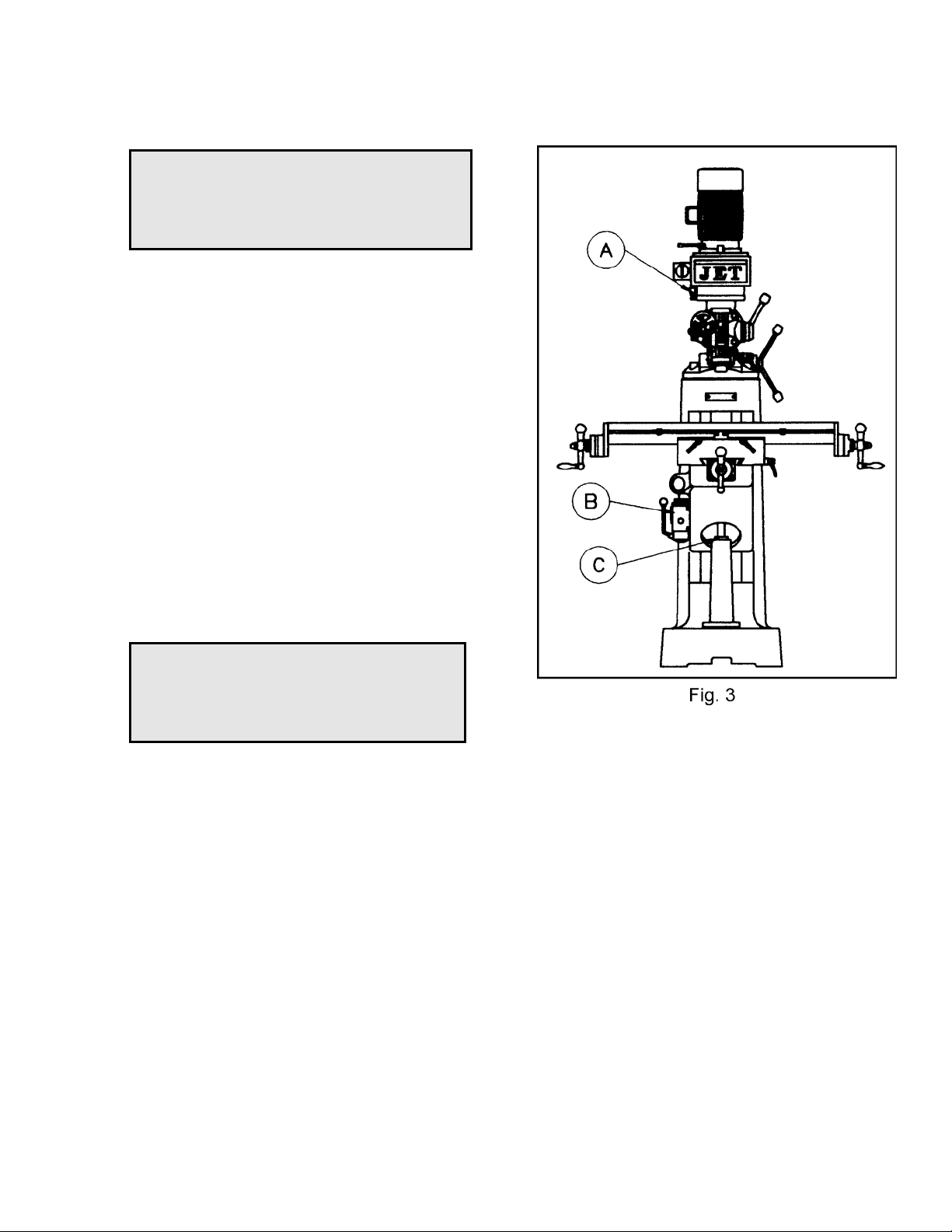
Lubrication
CAUTION!
Do not operate the mill before lubricating
the machine fully. Failure to comply may
cause damage to the machine.
Reference Fig. 3 for parts of the mill to
lubricate:
A. Spindle Bearings - fill oil cup once daily
with Mobil DTE® Oil Light.
B. Oil Pump - fill reservoir as needed by
removing cap on top of tank and filling with
Mobil Vactra Oil No. 2. Pump oil with
release handle once for every hour of
operation. Way surfaces and leadscrews
are lubricated in this manner.
C. Knee Leadscrew - lubricate with Mobilith®
AW2 once a week.
Electrical Connections
,WARNING
All electrical connections must be made by
a qualified electrician! Failure to comply
may cause serious injury!
The JVM-836-3 Mill is rated 1-1/2HP, 3Ph,
230V only. The JVM-836-1 Mill is rated at
1-1/2HP, 1Ph 115/230V and comes from the
factory prewired at 115V.
Confirm power at the site matches power
requirements of the mill before connecting to
the power source.
To change from 115V to 230V operation
(JVM-836-1 only), remove the junction box
cover on the motor and change the wires
according to the diagram found on the inside of
the cover.
The mill must be properly grounded.
7

Controls
A. Belt Cover Lock Knobs (A, Fig. 4) located
on the right side of the head. Loosen and
remove belt cover to change belt position
on the pulleys.
B. Spindle Brake (B, Fig. 4) located on left
side of the head. Move in either direction to
stop spindle once power has been turned
off.
C. Quill Feed Handle (C, Fig. 4) located on
the right side of the head. Rotate
counter-clockwise to lower spindle. Return
spring will retract the spindle automatically
once the handle is released.
D. Quill Lock (D, Fig. 5) located on the right
side of the head. Rotate the handle
clockwise to lock the quill in a desired
position. Rotate the handle
counter-clockwise to release.
E. Micrometer Adjusting Nut (E, Fig. 4)
located on the front of the head. Use for
setting specific spindle depth.
F. Manual Fine Feed (F, Fig. 4) located on
the left side of the head. Must engage fine
feed (I, Fig. 5) for handwheel to function.
G. Quill Stop (G, Fig. 4) located on the front of
the head. Used in conjunction with
micrometer adjusting nut for predetermined
depth.
H. Reversing Switch (H, Fig. 5) located on
the left side of the head. Switches rotation
of spindle. For 3 Ph motor there is an
additional low and high-speed option.
I. Fine Feed Engagement (I, Fig. 5) located
on the left side of the head. Turn clockwise
until tight. This engages the manual fine
feed.
J. Draw Bar (J, Fig. 5) located on the top of
the head. This is used to tighten a R-8
collet or R-8 tool into the quill. Tighten
draw bar enough to hold tool securely
during milling operations.
8

K. Longitudinal Movement (K, Fig. 6)
handles located on opposite ends of the
table. This controls the X axis.
L. Cross Movement (L, Fig. 6) handle
located directly in front of the machine.
This controls the Y axis.
M. Knee Handle (M, Fig. 6) this raises the
table up and down.
Changing Speeds
1. Unscrew two knobs (A, Fig. 4) and remove
belt cover.
2. Loosen hex nut (A, Fig. 7).
3. Take the tension off the belt by moving
handle (B, Fig. 7).
4. Use the RPM chart, located on the back of
the belt cover, to place the belt in the
desired position.
5. Place tension on the belt by moving
handle.
6. Tighten hex nut.
7. Always replace the belt cover!
Note: The 3 Ph motor has an additional low
and high-speed setting (H, Fig.5).
Position of Ram
CAUTION!
Care should be taken to lock ram securely
after setting.
Ram can be moved by loosening two
handles (A, Fig. 8), and turning handle (B, Fig.
8) to desired position.
Note: It is recommended while doing heavy
milling work the head should be left as close to
face of turret as possible. Maximum rigidity is
then obtained.
9

Adjustments
1. Knee Gib Adjustment (#53, page 18)
adjust gib screw (#18, page 18) below
wiper on the left side of the knee for proper
travel and excess play.
Note: when adjusting the gibs always start
with the knee. Adjust the saddle second,
and adjust the table last.
2. Saddle Gib Adjustment (#47, page 18)
adjust gib screw (#18, page 18) found on
the right side front of the carriage for proper
travel and excess play.
3. Table Gib Adjustment (#45, page 18)
adjust gib screw (#18, page 18) found on
the left side of the table toward the front of
the carriage for proper travel and excess
play.
4. Ram Ware Plate (#10, page 18) adjust two
set screws (#19, page 18) found on the
side of the ram for proper travel.
5. Head Alignment the scales on the ram
adapter and head rotation are guides only.
Close tolerance work will require the use of
a dial indicator to make sure the head is
90º to the table in the X axis.
6. Longitudinal and Crossfeed Adjustment
- if there is excessive backlash in the handle.
a) Loosen hex socket head screw (#27,
page 16).
b) Turn feed screw nut (#26 or #29, page
16) to remove play.
c) Tighten hex socket head screw.
10


 Loading...