


.JET
EQUIPMENT& TOOLS
OPERATOR'S MANUAL
JVM-836 Milling Machine
-,
)~.
.~
JET EQUIPMENT & TOOLS, INC.
A WMH Company
www.jettools.com
P.O. BOX 1349
Auburn, WA 98071-1349
e-mail jet@jettools.com
253-351-6000
Fax 800-274-6840
M-690036 5/00

Important Information
1-YEAR
LIMITED WARRANTY
JET offers a one-year limited
warranty on this product
REPLACEMENT PARTS
Replacementparts for this tool are available directly form JET Equipment& Tools.
To place an order,call 1-800-274-6848. Pleasehave the followinginformation ready:
1. Visa, MasterCard,or DiscoverCard number
2. Expirationdate
3. Part number listed within this manual
4. Shipping address other than a PostOfficebox.
REPLACEMENT PART WARRANTY
JET Equipment & Tools makes every effort to assure that parts meet high quality and durability
standards and warrants to the original retailconsumer/purchaserof our parts that each such part(s)
to be free from defects in materialsand workmanshipfor a period of thirty (30)days from the date of
purchase.
"P~O~.E.c)FPDRCHASE
Please retainyour dated sales receiptas proof of purchase to validate the warranty period.
LJMITEDTOOL AND EQUIPMENTWARRANTY
JET makes eVeryeffort to assure that its products meet high quality and durability standards and warrants to
the original retailconsumer/purchaserof our products that each product be free from defects in materialsand
workmanship as follows: 1 YEAR LIMITED WARRANTYON THIS JET PRODUCT. Warranty does not apply
to defects due directly or indirectlyto misuse, abuse,negligence or accidents, repairs or alterations outside our
facilities or to a lack of maintenance. JET LIMITSALL IMPLIEDWARRANTIESTO THE PERIOD SPECIFIED
ABOVE FROM THE DATETHE PRODUCT WAS PURCHASED AT RETAIL. EXCEPT AS STATEDHEREIN,
ANY IMPLIEDWARRANTIES OR MECHANTABILITYAND FITNESS ARE EXCLUDED. SOME STATESDO
NOT ALLOW LIMITATIONS ON HOW LONG THE IMPLIED WARRANTY LASTS, SO THE ABOVE
LIMITATIONMAY NOT APPLY TO YOU. JET SHALL IN NO EVENT BE LIABLE FOR DEATH,INJURIESTO
PERSONS OR PROPERY OR FOR INCIDENTAL, CONTINGENT, SPECIAL OR CONSEQUENTIAL
DAMAGES ARISING FROM THE USE OF OUR PRODUCTS. SOME STATES DO NOT ALLOW THE
EXCLUSION OR LIMITATION OF INCIDENTAL OR CONSEQUENTIAL DAMAGES, SO THE ABOVE
LIMITATIONOR EXCLUSION MAY NOT APPLYTO YOU. To take advantage of this warranty,the product or
part must be returned for examination, postage prepaid, to an authorized service station designated by our
Auburn office. Proof of purchase date and an explanation of the complaint must accompany the merchandise.
If our inspectiondiscloses a defect, JETwill either repair or replacethe product or refundthe purchase price, if
we cannot readilyand quickly providea repairor replacement,if you arewilling to accept such refund. JET will
return repaired product or replacement at JET's expense, but if it is determined there is no defect, or that the
defect resultedfrom causes not within the scope of JET's warranty,then the user must bearthe cost of storing
and returning the product. This warranty gives you specificlegal rights,and you have other rights,which vary,
from state to state.
JET Equipment &Tools. P.O.Box 1349, Auburn, WA98071-1349 . (253) 351-6000

it WARNING
1. Read and understand the entire
instruction manual before attempting
set-up or operation of this machine.
2. Always wear approved safety
glasses/face shields while usingthis
machine.
3. Makecertain the machine is properly
grounded.
4. Beforeoperating the machine, remove
tie, rings, watches, otherjewelry, and roll
up sleeves above the elbows. Remove
all loose clothing and confine long hair.
Do not wear gloves.
5. Keepthe floor around the machine clean
and free of scrap material, oil and
grease.
6. Keep machineguards in place at all
times when the machine is in use. If
removed for maintenancepurposes, use
extreme caution and replacethe guards
immediately.
12. Giveyour work undividedattention.
Lookingaround, carryingon a
conversation,and "horse-play" are
careless acts that can result in serious
injury.
13. Keepvisitors a safedistance from the
work area.
14. Use recommended accessories;
improper accessories may be
hazardous.
15. Keephandsaway from all moving parts
(belts,cutters, gears, etc.).
16. Neveroperatethis machine under the
influenceof alcohol or drugs.
17. Readand understandall warnings
posted on the machine.
18. This manual is intended to familiarize you
with the technical aspects of this milling
machine. It is not, nor was it intended to
be, a training manual.
7. Do not over reach. Maintain a balanced
stance at all times so that you do notfall
or lean against blades or other moving
parts.
8. Makeall machine adjustments or
maintenancewith the machine
unpluggedfrom the powersource.
9. Usethe right tool. Don'tforce a tool or
attachment to do ajob which it was not
designed for.
10. Replacewarning labels if they become
obscured or removed.
11. Make certain the motor switch is in the
OFF position before connecting the
machine to the power supply.
19. This machine is designed and intended
for use by properlytrained and
experienced personnel only. If you are
notfamiliar with the proper safe useof
millingmachines, do not usethis
machineuntil proper trainingand
knowledge has been obtained.
20. Failureto comply with all of these
warnings maycause serious injury.
2

Specifications
Stock Number .690036 JVM-836-1
Stock Number ..690038 JVM-836-3
Spindle Taper R-8
Diameter of Quill (in) 3-3/8
Number of Spindle Speeds (5) JVM-836-1
JVM-836
Numberof SpindleSpeeds , (10) JVM-836-3
Range of Spindle Speeds (rpm) ".. 240-1,550 JVM-836-1
Range of Spindle Speeds (rpm) 120-1,550 JVM-836-3
Spindle Travel (in) 5
Collet Capacity (in) 1/8-7/8
Head Movement 90° Land R
MaximumTravel of Ram (in) , 10-1/2
Maximum DistanceSpindle toTable (in) " 13-3/4
Minimum Distance Spindle to Column (in) 5-114
Maximum Distance Spindle to Column (in) 15-3/4
Maximum LongitudinalTableTravel (in) " 24
Maximum Cross TableTravel (in) , 9-1/2
Maximum Knee TableTravel (in) , 14
Size of Table (in) , 7-7/8 x 36
T-Slot (number) Size (in) (3) 5/8
T-Slot Centers (in) 2-1/2
Motor (JVM-836-1) ,
Motor (JVM-836-3) 1-1/2 HP, 3Ph 2 Speed
Floor Space Required (LxWxH/in) 55 x 52 x 77
Net Weight (approx.) .1474 Lbs.
\ 1-112HP,1Ph 115/230V
prewired 115V
.230V Only
Table of Contents
Page
Warranty 1
Warnings . 2
Specifications 3
Tableof Contents 3
Installation Layout 4
Shipping ContainerContents 5
Unpackingand Clean-Up 5
Raisingthe Head 5
Site Preparation 6
Lifting the Mill 6
Lubrication 7
ElectricalConnections 7
Controls 8-9
Changing Speeds 9
Positionof Ram 9
Adjustments ... 9
Parts Listsand Breakdowns , 11-21
Wiring Diagram 22
The specifications inthis manualare given as general informationand are not binding. JET Equipment
& Tools reservesthe rightto effect, at anytime and without prior notice, changes or alterationsto parts,
fittings, and accessory equipment deemed necessaryfor any reaso'nwhatsoever.
3

JVM-836 Installation Layout
5"
1916
16.5"
HOLD
DOWN
BOLT
A-A
~I<X)
<D
.M
M~
(\J
(Y)
CD
I
L..J
..
VIEW A-A
3"
74-
4

Shipping Container Contents
1. Mill
1. FlatWay Cover(rear)
1. AccordionWay Cover (front)
1. Knee Crank
1. Drawbar
1. Tool Box:
1. Hex Wrench Set (1.5 -10mm)
1. 17/19mm Combination Wrench
1. #2 Cross Point Screw Driver
1. #2 Flat Blade Screw Driver
1. Oil Can
1. Handwheel
1. Adjustable Wrench
5. Handles for Handwheels
1. Operator's Manual
1. Warranty Card
Unpacking and Clean-Up
1. Finish removing the sides and top of the
crate. Leave the mill bolted to the skid until
it is ready to be moved to its final location.
I
~..
~"
- -
2. Clean all rust protected surfaces with
kerosene or a light solvent. Do not use
gasoline, paint thinner, or lacquer thinner.
These will damage paintedsurfaces.
3. Cover all machined surfaces with a film of
light machinetool oil to inhibitrust.
4. Removewood block from below the knee.
Raising the Head
1. Remove handwheel (A, Fig. 1).
2. Loosen four cap nuts (B, Fig.1) with a Y2
turn to unlock the head. Do not remove
these nuts unless you are prepared to
remove the head.
3. Use a 19mm socket and breaker bar on
adjusting nut (C, Fig. 1)to raise the head.
A L
Fig.1
5

Site Preparation
CAUTION!
Mill must be supported equally under all
four corners. Failureto comply may cause
the column to twist and put a bind in the
bedways.
The millmust beplacedon an even surface
and bolted to the floor. Anchor bolts of
sufficient size and length must be fastened to
the floor according to the footprint of the mill.
See Installation Layout page4.
Lifting the Mill
~WARNING
Keep people a safe distance away from the
milling machine while ifis being moved.
Failure to comply may cause serious injury!
A A
Lift the mill with appropriate sized lifting
straps. Follow the diagram in Fig. 2 for the
proper position of the straps under the ram.
Note: the position of the ram, and that the
table has been moved against the column.
Tighten ram locking bolts (A, Fig. 2) before
lifting.
Carefully lift the mill. Move into position
over the anchor bolts. Lower the mill onto the
anchor bolts. Check for level, and securewith
washers and anchor bolt nuts.
Check the mill for level with a machinist's
level placed on the table. Mill must be level
back to front and side to side. Shim if
necessary, but rememberthat the mill must be
supportedequally at allfour corners. Checkfor
level beforetightening the anchor boltnuts and
after tightening them. Adjust as necessary.
D
Fig. 2
6

Lubrication
CAUTION!
Do not operate the mill before lubricating
the machine fully. Failure to comply may
Ccil'$e damage to ttle machine.
Reference Fig. 3 for parts of the mill to
lubricate:
A. Spindle Bearings - fill oil cup once daily
with MobilDTE@Oil Light.
B. Oil Pump - fill reservoir as needed by
removingcap on top of tank and fillingwith
Mobil Vactra Oil NO.2. Pump oil with
release handle once for every hour of
operation. Way surfaces and leadscrews
are lubricated inthis manner.
C. Knee Leadscrew - lubricatewith Mobilith@
AW2 once a week.
Electrical Connections
LtWARNING
All electrical connections must be made by
a qualified electricIan! Failure to comply
may cause serious injury!
The JVM-836-3 Mill is rated 1-1/2HP,3Ph,
230V only. The JVM-836-1 Mill is rated at 1-
1/2HP, 1Ph 115/230V and comes from the
factory prewired at 115V.
Confirm power at the site matches power
requirements of the mill before connecting to
the power source.
To change from 115V to 230V operation
(JVM-836-1 only), remove the junction box
cover on the motor and change the wires
accordingto the diagram found on the insideof
the cover.
Fig. 3
The mill must be properly grounded.
7

Controls
A. Belt Cover LockKnobs (A,Fig.4) located
on the right side of the head. Loosen and
remove belt cover to change belt position
on the pulleys.
B. Spindle Brake (B, Fig. 4) located on left
sideof the head. Move ineitherdirectionto
stop spindle once power has been turned
off.
C. Quill Feed Handle (C, Fig. 4) located on
the right side of the head. Rotate counter-
clockwise to lower spindle. Return spring
will retract the spindle automatically once
the handle is released.
D. Quill Lock (0, Fig. 5) located on the right
side of the head. Rotate the handle
clockwise to lock the quill in a desired
position. Rotate the handle counter-
clockwise to release.
E. Micrometer Adjusting Nut (E, Fig. 4)
located on the front of the head. Use for
setting specific spindle depth.
B-II"""-"-
G
F
E
Fig. 4
F. Manual Fine Feed (F, Fig. 4) located on
the left side of the head. Mustengage fine
feed (I, Fig.5) for handwheel to function.
G. Quill Stop (G, Fig. 4) located on the front
of the head. Used in conjunction with
micrometer adjusting nut for predetermined
depth.
H. Reversing Switch (H, Fig. 5) located on
the left side of the head. Switches rotation
of spindle. For 3 Ph motor there is an
additional low and high-speed option.
I.
Fine Feed Engagement(I, Fig.5) located
on the leftside of the head. Turnclockwise
until tight. This engages the manual fine
feed.
J. Draw Bar (J, Fig. 5) located on the top of
the head. This is used to tighten a R-8
collet or R-8 tool into the quill. Tighten
draw bar enough to hold tool securely
during milling operations.
J
H
".. CI
Fig. 5
8

K. Longitudinal Movement (J, Fig. 6)
handles located on opposite ends of the
table. This controls the X axis.
L. Cross Movement (K, Fig. 6) handle
located directly in front of the machine.
This controls the Y axis.
M. Knee Handle (L, Fig. 6) this raises the
table up and down.
Changing Speeds
1. Unscrew two knobs (A, Fig. 4) and remove
belt cover.
I
K
2. Loosen hex nut (A, Fig. 7).
3. Take the tension off the belt by moving
handle (B, Fig. 7).
4. Use the RPM chart, locatedon the back of
the belt cover, to place the belt in the
desired position.
5. Place tension on the belt by moving
handle.
6. Tighten hex nut.
7. Always replacethe belt cover!
Note: The 3 Ph motor has an additional low
andhigh-speedsetting(H, Fig.5).
Position of Ram
CAUTION!
..... -,'
Fig.6
_II
'
~:'
I
.
Fig.7
Care should be taken to lock ram securely
after setting.
Ram can be moved by loosening two
handles (A, Fig. 8), andturning handle(B, Fig.
8) to desired position.
Note: It is recommended while doing heavy
millingwork the headshould be left as closeto
face of turret as possible. Maximum rigidity is
then obtained.
B
Fig.8
9

Adjustments
1. Knee Gib Adjustment (#53, pages 21 &
23 of the parts list and breakdown) adjust
gib screw (#18, pages 21 & 22) below
wiper on the left side ofthe knee for proper
travel and excess play.
Note: when adjustingthe gibs always start
with the knee. Adjust the saddle second,
and adjust the table last.
2. Saddle Gib Adjustment (#47, pages 21 &
23 of the parts list and breakdown) adjust
gib screw (#18, pages 21 & 22) found on
the rightsidefront of thecarriagefor proper
travel and excess play.
3. Table Gib Adjustment (#45, pages 21 &
23 of the parts list and breakdown) adjust
gib screw (#18, pages 21 & 22) found on
the leftside of the table toward the front of
the carriage for proper travel and excess
play.
4. Ram Ware Plate (#10, pages 21 & 22 of
the parts list and breakdown) loosen two
hex nuts (#19-1, pages 21& 22) adjusttwo
set screws (#19, pages 21 & 22) found on
the side of the ram for proper travel.
Tighten hex nuts.
5. Head Alignment the scales on the ram
adapter and head rotation are guides only.
Close tolerance work will requirethe useof
a dial indicator to make sure the head is
90° to the table inthe X axis.
6. Longitudinal and Crossfeed Adjustment
if there is excessive backlash in the handle.
a) Loosen hex socket head screw (#27,
pages 19 & 20 of the parts list and
breakdown).
b) Turn feed screw nut(#26or#29, pages
19& 20 of the parts listand breakdown)
to remove play.
c) Tighten hex socket head screw.
10

HeadAssembly
94.
.Ai 91-1 89 I23 25
/ I (i) " 90--1 839 i" 0 ~ 26
1 ~f, ~ 3 1353637 I ~l<lL'3233
2 3 ,/5?/"A 910 ""I . ~WJJ 3'
~-
~~4?
\;
02 '5 V 0 56 . oi 18
6Y"
~
5\- / -.v / . ~86--1
~
44 . : . 17
,\'i 5~~ :
\\\ 55~/t 6~8' ~
67 ~IJ3 1@-79
6~j::? f! ~5 64 59 ~ i ~80
'1405 6 7 ~ 0 8788 ~)2/ ~~ ~
'3'\ \~ 853/(,. 15 14 ',27)' 28
66././0 96 0
/
I
0/54
'" 'i' 97 9- 78
Q-92 19
I:§ 16 ! 29
~
5 0-85
69 I
-70 0
98
( 0 -L
I
'
~
~ ~I I
~
30 <>\
22
31
)
I
72 @ ...;::::.83 I
@..=73°
75-@~101 I
~781
8-76 I
6-/0)
L,-%
11
100
1
81
82
83
. - - u
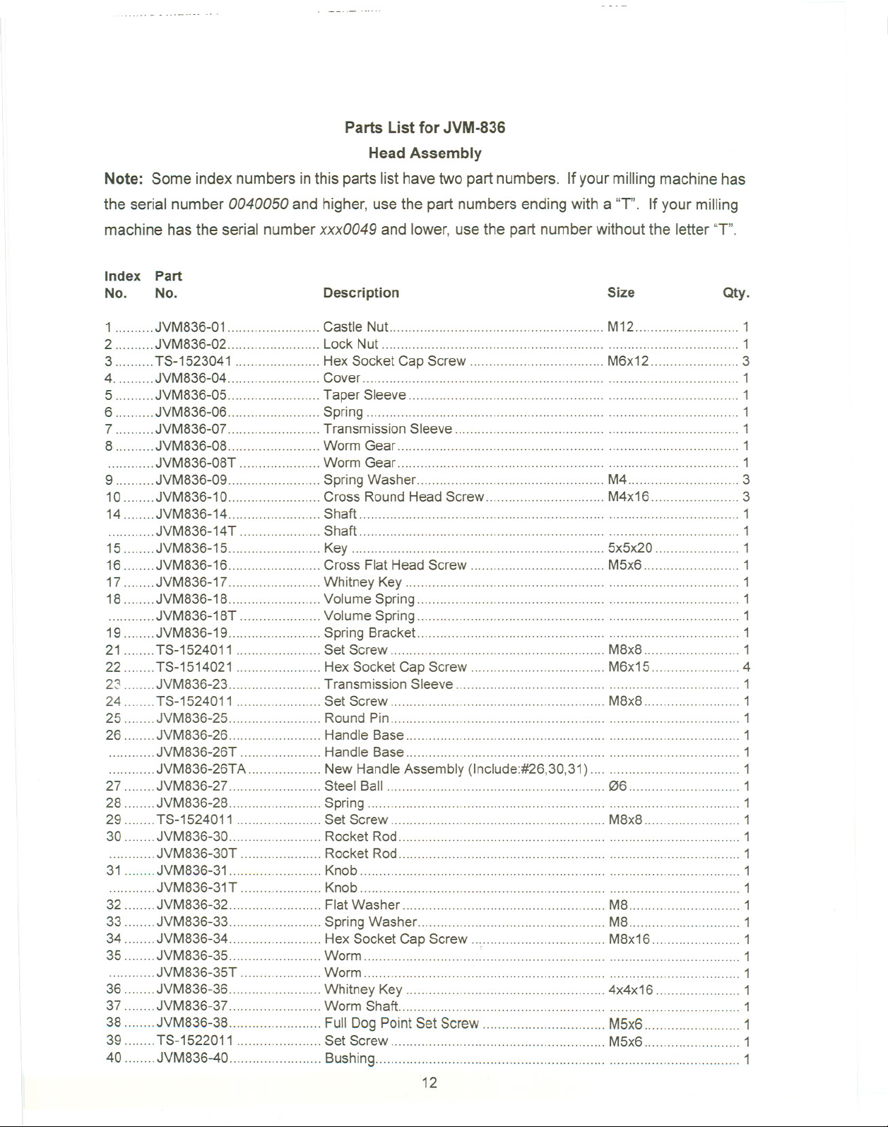
Parts List for JVM-836
Head Assembly
Note: Some index numbers inthis parts listhavetwo part numbers. If yourmilling machinehas
the serial number 0040050 and higher, usethe partnumbersending with a 'T'. If your milling
machine has the serial numberxxx0049 and lower,use the part numberwithout the letter"T".
Index Part
No. No.
1 JVM836-01 Castle Nut -.. M12 1
2 JVM836-02 Lock Nut 1
3 TS-1523041 Hex SocketCap Screw M6x12 3
4. JVM836-04 Cover 1
5 JVM836-05 Taper Sleeve 1
6 JVM836-06 Spring 1
7 JVM836-07 Transmission Sleeve 1
8 -.JVM836-08 Worm Gear 1
JVM836-08T Worm Gear -.. -.. 1
9 JVM836-09 Spring Washer M4 3
10 JVM836-10 Cross RoundHead Screw M4x16 3
14 JVM836-14 Shaft 1
JVM836-14T Shaft 1
15 JVM836-15-.. Key 5x5x20 ..................1
16 JVM836-16 Cross Flat HeadScrew M5x6 1
17 JVM836-17 Whitney Key 1
18 JVM836-18 Volume Spring"'"'''''''''''''''''''''''''''''''''''''''''''' 1
. JVM836-18T Volume Spring 1
19 JVM836-19 Spring BrackeL 1
21 TS-1524011 Set Screw M8x8 1
22 TS-1514021 Hex SocketCap Screw M6x15 4
2~ JVM836-23 TransmissionSleeve 1
24 TS-1524011 Set Screw M8x8 1
25 JVM836-25 Round Pin 1
26 JVM836-26 HandleBase 1
JVM836-26T Handle Base 1
JVM836-26TA New HandleAssembly (Include:#26,30,31) 1
27 JVM836-27 Steel Ball 06 1
28 JVM836-28 Spring 1
29 TS-1524011 Set Screw M8x8 1
30 JVM836-30 Rocket Rod 1
JVM836-30T Rocket Rod . 1
31 JVM836-31 Knob 1
JVM836-31T Knob . 1
32 JVM836-32 FlatWasher M8 1
33 JVM836-33 Spring Washer M8 1
34 JVM836-34 Hex SocketCap Screw M8x16 1
35 JVM836-35 Worm 1
JVM836-35T Worm 1
36 JVM836-36 Whitney Key 4x4x16 1
37 JVM836-37 Worm Shaft 1
38 JVM836-38 Full DogPointSetScrew M5x6 1
39. TS-1522011 Set Screw M5x6 1
40 JVM836-40 Bushing 1
Description
12
Size
Qty.
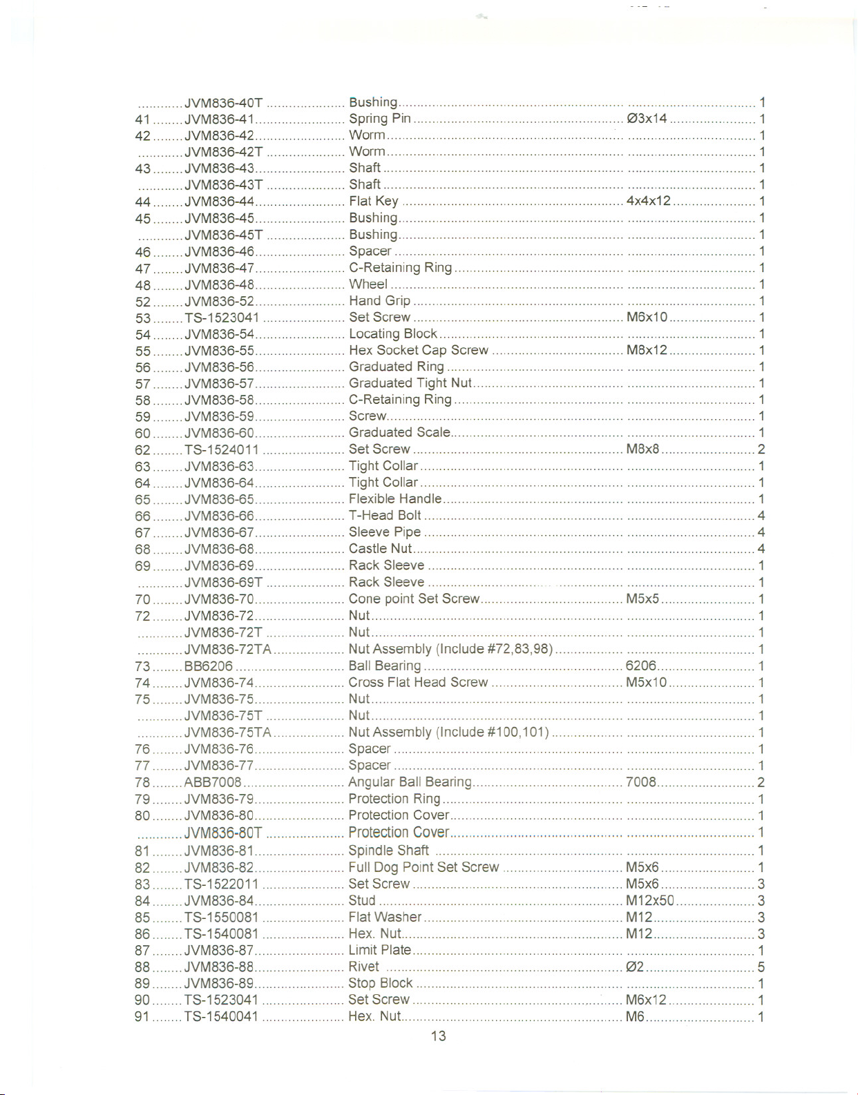
JVM836-40T... Bushing...... ... ... ...... ... 1
41 JVM836-41 SpringPin , 03x14 1
42 JVM836-42 Worm 1
, JVM836-42T Worm 1
43 JVM836-43 Shaft 1
JVM836-43T Shaft 1
44 JVM836-44 Flat Key 4x4x12 1
45 JVM836-45 Bushing 1
JVM836-45T Bushing 1
46 JVM836-46 Spacer 1
47 JVM836-47 C-Retaining Ring 1
48 JVM836-48 Wheel 1
52 JVM836-52 Hand Grip 1
53 TS-1523041 Set Screw M6x10 1
54 JVM836-54 Locating Block 1
55 JVM836-55 Hex Socket Cap Screw M8x12 1
56 JVM836-56 GraduatedRing 1
57 JVM836-57 Graduated Tight Nut 1
58 JVM836-58 C-Retaining Ring 1
59 JVM836-59 Screw 1
60 JVM836-60 GraduatedScale 1
62 TS-1524011 Set Screw M8x8 2
63 JVM836-63 Tight Collar 1
64 JVM836-64 Tight Collar 1
65 JVM836-65 Flexible Handle 1
66 JVM836-66 T-Head Bolt 4
67 JVM836-67 Sleeve Pipe 4
68 JVM836-68 Castle Nut 4
69 JVM836-69 Rack Sleeve 1
JVM836-69T Rack Sleeve 1
70 JVM836-70 Cone pointSet Screw M5x5 1
72 JVM836-72 Nut 1
JVM836-72T Nut 1
JVM836-72TA NutAssembly (Include#72,83,98) 1
73 BB6206 Ball Bearing""""""""""'"'''''''''''''''''''''''''''''' 6206 1
74 JVM836-74 Cross FlatHead Screw M5x10 1
75 JVM836-75 Nut 1
JVM836-75T Nut 1
JVM836-75TA NutAssembly (Include#100,101) 1
76 JVM836-76 Spacer 1
77 JVM836-77 Spacer 1
78 ABB7008 Angular Ball Bearing 7008 2
79 JVM836-79 Protection Ring 1
80 JVM836-80 ProtectionCover 1
JVM836-80T ProtectionCover ... 1
81 JVM836-81 Spindle Shaft 1
82 JVM836-82 Full Dog PointSet Screw M5x6 1
83 TS-1522011 Set Screw M5x6 3
84 ...JVM836-84. ...... Stud M12x50 ... 3
85 TS-1550081 Flat Washer M12 3
86 TS-1540081 Hex. Nut M12 3
87 JVM836-87 Limit Plate 1
88 JVM836-88 Rivet 02 5
89 JVM836-89 Stop Block 1
90 TS-1523041 Set Screw M6x12 1
91 TS-1540041 Hex. Nut M6 1
13

92 TS-41490011 Hex.Screw M8x12 1
93 JVM836-93 OilCan 1/16"PS 1
94.. JVM836-94 ... HeadBody 1
JVM836-94T HeadBody 1
95 JVM836-95 Cross RoundCapScrew M5x6 2
96 JVM836-96 Plate 1
97 JVM836-97 Cover 1
98 JVM836-98 AluminumBlock 04X3 2
100 JVM836-100 AluminumBlock 06X3 2
101 JVM836-101 Set Screw M8x8 2
102 JVM836-102 Set Screw M5x6 1
14

Head Assembly
Used with Serial Number 0050104 and Higher
94 Q--92
22 // 31
fi@ 91_V I2325
/ I @ 93 90-1 39 0 ~ 26
1 ~~~fA~\ ~11:ar ~~~~
43 1 /' '"d
~ 56. -
44 '-' - - 00' '.d>");':! 62 84 /'\oJ
102 .0 '~/ (QJ
'<:Y 6~/ / 96
47
57~~ '" ~ ~ 950-85
/ ~ / @J.-86
o~ B7
1
0-
~~ /' I 97 ~
f( f63 98
68
~ \ 67 65 59 -83 '
/2 64 / ~80
r
[
I
@-79
~
dtp
17 I
~ 18
71-1
~ )
V'"
15
70 I
I
81
82
I
83

Head Assembly
Used with Serial Number 0050104and Higher
Note: Some index numbers inthis partslisthavetwo part numbers. Ifyour millingmachine has
the serial number 0040050 and higher, usethe partnumbersending with a "T". If your milling
machine has the serial numberxxx0049 and lower, usethe part numberwithout the letter'T'.
Index Part
No. No.
1 JVM836-01 Castle NuL M12... 1
2 JVM836-02 Lock Nut 1
3 TS-1523041 HexSocket Cap Screw M6x12.. 3
4. JVM836-04 Cover 1
5 JVM836-05 .Taper Sleeve 1
6 ...JVM836-06 .........Spring ......... ... ... ...... ...... 1
7 JVM836-07 Transmission Sleeve 1
8 JVM836-08 Worm Gear 1
JVM836-08T Worm Gear 1
9 JVM836-09.. Spring Washer ... M4 3
10 JVM836-10 ... Cross RoundHeadScrew M4x16 3
14 JVM836-14 Shaft 1
JVM836-14T Shaft 1
15 JVM836-15 ... Key 5x5x20 1
16 JVM836-16 Cross FlatHeadScrew M5x6 1
17 JVM836-17 Whitney Key 1
18 JVM836-18 Volume Spring 1
. JVM836-18T Volume Spring ... 1
19 JVM836-19 Spring Bracket , 1
21 TS-1524011 Set Screw ... M8x8 1
22 TS-1514021 Hex SocketCap Screw M6x15 4
23 JVM836-23 TransmissionSleeve 1
24 TS-1524011 Set Screw M8x8 1
25. ... JVM836-25 ... ... Round Pin 1
26. JVM836-26 Handle Base ... ... ... .........1
JVM836-26T HandleBase 1
JVM836-26TA New HandleAssembly (Include:#26,30,31) 1
27 JVM836-27 Steel Ball 06 1
28 JVM836-28 Spring 1
29 TS-1524011 Set Screw M8x8 1
30 JVM836-30 RocketRod 1
JVM836-30T RocketRod 1
31 JVM836-31 Knob 1
JVM836-31T ... Knob ...1
32 JVM836-32 FlatWasher M8 1
33 JVM836-33 Spring Washer M8 1
34 JVM836-34 HexSocket Cap Screw M8x16 1
35 JVM836-35 Worm 1
JVM836-35T Worm 1
36 JVM836-36 Whitney Key 4x4x16 1
37 JVM836-37 Worm Shaft..... ... 1
38 JVM836-38 Full Dog PointSet Screw M5x6 1
Description
Size
Qty.
\16

39 TS-1522011 Set Screw M5x6 1
40 JVM836-40 Bushing 1
JVM836-40T Bushing 1
41 JVM836-41 Spring Pin 03x14 1
42 JVM836-42 Worm ..." 1
JVM836-42T Worm 1
43 JVM836-43 Shaft 1
JVM836-43T Shaft 1
44 JVM836-44 Flat Key 4x4x12 1
45 JVM836-45 Bushing 1
JVM836-45T Bushing 1
46 JVM836-46 Spacer 1
47 JVM836-47 C-Retaining Ring 1
48 JVM836-48 Wheel 1
52 JVM836-52 Hand Grip 1
53 TS-1523041 Set Screw M6x10 1
54 JVM836-54 Locating Block 1
55 JVM836-55 Hex Socket Cap Screw M8x12 1
56 JVM836-56 Graduated Ring 1
57 JVM836-57 Graduated Tight Nut 1
58 JVM836-58 C-Retaining Ring 1
59 JVM836-59 Screw 1
60 JVM836-60 Graduated Scale 1
62 TS-1524011 Set Screw M8x8 2
63 JVM836-63 Tight Collar 1
64 JVM836-64 Tight Collar 1
65 JVM836-65 Flexible Handle 1
66 JVM836-66 T-Head Bolt 4
67 JVM836-67 Sleeve Pipe 4
68 JVM836-68 Castle Nut 4
69 JVM836-69 RackSleeve 1
JVM836-69T Rack Sleeve 1
69-1 JVM836-69T-1 C-Clip R62 1
70 JVM836-70 Cone pointSet Screw M5x5 1
71 JVM836-71 Taper RollerBearing 30206 1
71-1 JVM836-71-1 Taper Roller Bearing 32008 1
72 JVM836-72 Nut 1
JVM836-72T Nut 1
JVM836-72TA NutAssembly (Include #72,83,98) 1
74 JVM836-74 Cross Flat HeadScrew M5x10 1
79 JVM836-79 Protection Ring 1
80 JVM836-80 Protection Cover 1
JVM836-80T Protection Cover 1
81 JVM836-81 Spindle Shaft 1
82 JVM836-82 Full Dog Point Set Screw M5x6 1
83 TS-1522011 Set Screw M5x6 3
84 JVM836-84 Stud M12x50 3
85 TS-1550081 FlatWasher M12 3
86 TS-1540081 Hex.Nut M12 3
87 JVM836-87 LimitPlate 1
88 JVM836-88 Rivet 02 5
89 JVM836-89 Stop Block 1
90 TS-1523041 Set Screw M6x12 1
91 TS-1540041 Hex. Nut :.. M6 1
92 TS-41490011 Hex.Screw M8x12 1
93 JVM836-93 Oil Can 1/16"PS 1
17

94 JVM836-94 HeadBody 1
JVM836-94T HeadBody 1
95 JVM836-95 CrossRoundCapScrew M5x6 2
96 JVM836-96 Plate 1
97 JVM836-97 Cover 1
98 JVM836-98 AluminumBlock 04X3 2
102 JVM836-102 SetScrew M5x6 1
.18

Upper Head Assembly
23
3
2~
17
19'1D11
20 "'in
42
41~~
40, ..
39~
29 30
J.~
34
I
35
I
i/38 46
IT /37
19
;/36

Upper Head Assembly
Note: Some index numbers in this parts list have two part numbers. If your milling machine has
the serial number 0040050 and higher, use the part numbers ending with a'T'. If your milling
machine has the serial number xxx0049 and lower, use the part number without the letter "1".
Index Part
No. No.
2 VM-G22-1 Spacer 1
3 VM-G22 Draw Bar 1
4 VM-M3-1 Knob 1
VM-M3-1T Knob 1
5 VM-M3-3 BreakHandle 1
VM-M3-3T Break Handle 1
9 VM-M11-1 Jam Nut 1
10 TS-1514021 Hex Socket Cap Screw M6x16 6
11 VM-M4 """"""""""'''''''''' Fixed Cover .., 1
VM-M4T Fixed Cover 1
12 VM-M3-5 Brake Rod 1
...VM-M3-5T... Brake Rod...... ... ... ............ ... ......... 1
13 BB6007ZZ Ball Bearing 6007ZZ 1
14 VM-M2 Brake 1
VM-M2T Brake 1
VM-M2TA BrakeAssembly (Include#14,15,48,49) 1
15 VM-M1 . Screw 1
VM-M1T .., Screw 1
16 VM-M6 Brake Disc 1
17 VM-M8 Pulley............. ... ...... ... ... .... ...... ... 1
18 VM-M11 Spindle Shaft 1
19 VM-M7 Whitney Key 6x6x16 1
20 VM-M9 Whitney Key 6X6X32 1
21 BB6007ZZ Ball Bearing 6007ZZ 1
22 .VM-M5 C-RetainingRing 062 1
23 VM-M25 Motor (1-1/2HP 1 PH) 1
VM-M25-3Ph Motor (1-1/2HP3 PH) 1
24 VM-M21 """"'''''''''''''''''''' Hex. HeadScrew M10x25 4
25 VM-M25-1 Flat Key 8x7x36 1
26 VM-M19 Pulley 1
27 TS-1524011 Set Screw M8x8 1
28 VM-M20 Motor Cover 1
VM-M20T MotorCover 1
29 VM-M3 Rod 1
VM-M3T Rod 1
30 VM-M3-1 Knob 1
VM-M3-1T Knob 1
31 JVM836-31B Cross Flat HeadScrew M6x6 3
32 VM-M12-2 Cover ' 1
33 VM-M12 Pulley Housing 1
34 VM-M12-1 Cover 1
35 VM-DM85 Screw 2
36 TS-1540081 Hex. Nut M12 1
37 T8-1550081 FlatWasher M12 1
38 VM-M23-1 Stud M12x50 1
Description
Size
Qty.
20

39 TS-1540081 Hex. Nut M12 2
40 TS-1550081 Flat Washer M12 1
41 VM-M23-1 Stud M12x50 1
42 JVM836-42B Switch Assembly (1Ph) 1
JVM836-42-3Ph Switch Assembly (3Ph) 1
43 JVM836-43B , Hex Socket Cap Screw M6x8 4
44 JVM836-44B Switch Cord (4C,1 Ph) 1
,..JVM836-44-3Ph Switch Cord (6C,3Ph) 1
45 VB-A29 Belt A29 """'"'''''''''''''''''' 1
46 VM-M26 """'"'''' Spindle Speed Chart 1
48 VM-M2-1 Spring '''''''''''''''''''''''''''''''''' 2
49 VM-M2-2 " Cross Round Cap Screw 2
50 JVM836-U50 " Plastic Electrical Box 1
51 JVM836-U51 Cross Round Cap Screw M5x40L 2
21

15
r-
CD
I»
c..
III
(")
...
N
N
CD
:IE
~
III
III
CD
3
C"
-<
~~17 30
12?~~ij~1
5 4 2~~
3

LeadscrewAssembly
Note: Some index numbers in this parts list have two part numbers. If your milling machine has
the serial number 0040050 and higher, use the part numbers ending with a'T'. If your milling
machine has the serial number xxx0049 and lower, use the part number without the letter "T".
Index Part
No. No.
1 VM-11 ... CastleNut.. M12... 3
2 VM-12 Handle 3
3 VM-12-1 Ball Handle"'''''''''''''''''''''''''''''''''''''''''''''''''''' 3
4 VM-13 Knurled Nut 3
VM-13T Knurled Nut 3
5. VM-15 ......... Dial... 3
VM-15T Dial 3
6 VM-124 Dial Holder 2
VM-124T Dial Holder 2
VM-124TA Dial HolderAssembly (Include#4,5,6,30) 1
7 VM-16. ... ...Dial Holder. ... ... ......... . ... ... 1
VM-16T Dial Holder 1
VM-16TA Dial HolderAssembly (Include#4,5,7,30) 1
8 VM-18 BearingRetaining Cover 2
9 TS-1515011 Hex SocketCap Screw M8x16 6
10 VM-M26 Limit Plate 3
11 VM-M26-1 River 6
12 BB6204 Ball Bearing 6204 5
14 VM-114 BearingBracket 1
15 VM-118 ......... BearingBracket ...... 1
16 VM-J11 Bearing Block 1
17 VM-113 Hex. SocketScrew M10x16 8
18 VM-112 Taper Pin 08x130 6
19 TS-1515021 HexSocket Cap Screw M8x20 4
20 JVM836-20B FlatScrew M6x6 2
21 VM-14 Whitney Key 3x3x28 3
22 VM-J16 Lead Screw 1
23 VM-115 LeadScrew 1
24 VM-J28 Feed Nut Bracket 1
25 VM-J26-1 Feed Screw NuL 1
26 VM-J26 Feed Screw Nut 1
27 TS-1514021 Hex. SocketScrew M6x16 16
28 VM-J25-1 ........ FeedScrew Nut ... 1
29 VM-J25 FeedScrew Nut 1
30 JVM836-T30 Spacer "'''''''''''''''''''''''''''''''' 3
Description
Size
Qty.
23

N
.j:>.
8
7
41
'82
21
25
51
-" i«22
84
77
27
43
29
52
26
28
36
61
76

BaseAssembly
Note: Some index numbers in this parts list have two part numbers. If your milling machine has
the serial number 0040050 and higher, use the part numbers ending with a IT'. If your milling
machine has the serial number xxx0049 and lower, use the part number without the letter "T".
Index Part
No. No.
1 VM-L11 Worm Gear 1
VM-L11T Worm Gear 1
2 VM-L13 Taper Pin 08x150 1
3 TS-1505031 Hex SocketCap Screw M1Ox25 3
4 VM-L10 Graduation DiaL 1
4-1 VM-L10-1 Graduation Dial Plate 1
5 VM-L9 Taper Pin 08x130 2
6 TS-1515011 Hex Socket CapScrew M8x16 8
7 VM-L15 Ram 1
8 JVM836-08B Eye Bolt M16 1
9 VM-L6 Turret 1
10 VM-L5 Turret Gib 1
11 VM-L1-1 Knob 1
VM-L 1-1T ... Knob. ... ... ... ......... ... ... . 1
12 VM-L1 Handle 1
VM-L1T Handle 1
13 VM-L3 PinionShaft 1
VM-L3T .. ... PinionShaft... ... ... 1
VM-L3TA PinionShaft Assembly (Include#11,12,13) 1
14 VM-L2 FullDog Point Set Screw M6x12 1
16 TS-1550081 FlatWasher ... M12 4
17 VM-K12 Stud (S/N:0040063& lower) M12x105 4
VM-K12N Stud (S/N:0040064& higher) M12x115 4
18 JVM836-18B Adjustable Screw 6
19 TS-1523021 SetScrew M6x10 2
19-1. TS-1540041. Hex Nut.. ... ... M6 2
20 VM-L4 LockHandle M1Ox40 5
21 VM-L7 GraduatedScale 1
22 VM-L7-1 Rivet 02 7
23 VM-K11 Spider Arm 1
24 VM-K9 Base 1
25 VM-K17 Limit plate 2
26 VM-K5 Plate 1
27 JVM836-27B Cross Flat Screw M6x6 22
JVM836-27BT Cross Round Cap Screw M5x12 6
28 VM-K13 Plate 2
29 JVM836-29 Hex. Socket Screw M8x12 2
30 VM-H29 ElevatingNut 1
31 TS-1523051 Set Screw M6x15 1
32 VM-H30 ElevationScrewStand 1
33 VM-H30-1 HexSocket Cap Screw M10x30 2
34 VM-K2 Strainer Net 2
35 VM-137 Table...... ... 1
36 VM-140 Oil Plug 3/8"PT 2
Description
25
Size
Qty.

38 VM-133-2 Hex. SocketScrew M8x20 2
39 VM-133 StopRing 2
40 VM-133-1...... ... ...T-Nut ... ... ........................ ..... ... 2
41 VM-C-100 ... Dust Plastic ... ... ... ... 1
42 VM-H32 Wiper 3
43 VM-H32-1 Wiper 3
44 VM-J36 Saddle 1
45 VM-132 SaddleGib 1
46 VM-J39-1 Shoe 2
47 VM-J20 Saddle Gib 1
48 VM-J30 Table Stop Bracket 1
49 TS-1515021 Hex Socket CapScrew M8x20 2
50.. VM-J29-1 ... ... Shoe ...... ... ... ... ... 4
51 VM-C-101 DustPlastic 1
52 VM-H35 Knee 1
53 VM-H34 KneeGib 1
55 TS-1540081 Hex. NuL M12 2
56 VM-H19 SpringWasher M12 2
57 TS-1550081 FlatWasher M12 2
58 VM-H17 Straight BevelGear 1
60 BB6204 Ball Bearing 6204 2
61 VM-H6 Whitney Key 5x5x16 3
62 VM-H12 Shaft 1
VM-H12T Shaft 1
63 VM-H11 Bearing Block 1
64 TS-1514021 Hex Socket CapScrew M6x16""""'"'''''''''''' 3
65 VM-H7 C-RetainingRing 047 1
66 VM-H5 Dial Holder 1
VM-H5T Dial Holder 1
VM-H5TA Dial HolderAssembly (Include#66,67,68,69,71,90) 1
67 VM-H3 Dial 1
VM-H3T Dial 1
68 VM-H2 Knurled NuL . 1
VM-H2T KnurledNut 1
69.. VM-H4.. Clutch Insert ...... ...... 1
"'''''''''' VM-H4T Clutch Insert 1
71 VM-H1 Hand Lever 1
VM-H1T Hand Lever 1
73 VM-H1-3 HandGrip 1
74 VM-H24 Straight BevelGear 1
VM-H24T Straight Bevel Gear 1
75 BB6204 Ball Bearing 6204 2
76 VM-H27 ElevatingScrew """"""""""""""""" 1
77 VM-J37-1 UpperChip Guard 1
78 VM-J37 Lower Chip Guard 1
79 VM-H25 Bearing Housing 1
80 TS-1514031 Hex Socket Cap Screw M6x20 3
81 JVM836-B81 C-Clip S47 1
82 VM-139 RubberT-NuL 6
83 JVM836-B83 Key 3x3x28 1
84 JVM836-B84 Cross RoundCap Screw M6x10 9
85 JVM836-B85 Cross RoundCap Screw M6x12 7
86 JVM836-B86 Lock Handle M10x20 2
89 JVM836-B89 Spacer'"'''''''''''''''''''''''''''''''''''''''''''''''''''''''''' 1
90 JVM836-B90 Spacer 1
91 JVM836-B91 Oil Block 1/4" 1
26

One Shot Lubrication System
Index Part
No. No.
Description
Size
Qty.
1 JVM836-HP Hand Oiling Pump 1
2 JVM836-ALMP Aluminum Pipe 1
3 JVM836-DB Oil Regulating Distributor 1
4 JVM836-TJ T-Joint 1
5 JVM836-FST FlexibleSteel Tube 1
6 JVM836-CJ Check Joint 2
7 ..., JVM836-EJ ElbowJoint 2
10 TS-1514021 HexSocket Cap Screw M6x16 4
11 TS-1503061 Hex SocketCap Screw M6x25 2
12 TS-1503061 HexSocket Cap Screw M6x25 1
B-Longitudinal Slide Way
, ,
L-Knee' Slide ~ay
I'
I
1
17
I
I
I
I
I
I
1
I
I
I
I
I
I
I
L-
Longitudinal Feed Nut Bracket
I
1
F-Longitudinal Slide Way
I
L-Cross Slide Way
Cross Feed Nut Bracket
L
Cross Slide Way
I .
R-Knee ,Shde Way
1
I
I
i
I
I
I
I
I
)
27

Model No. JVM-836-1
Model No. JVM-836-3
1 Phase Wiring Diagram
Low Volt
110/115V
Power
j-r-l1 j-r-l1 i A t ~ i ~
~
00 1 I I - 1 '- 1- _I I (Q
I
I <B> CID I I (8) ~ I I ~ ~ Q) I -.
I~~I
I. Switch I I §.witcll I 1 -. Swj!ch -. I ~
I I
1--1
L ~ L ~
1 Motor 1
11 11
High Volt
220/230V
Power
I~~'
II I
1--1"" " "" 3
r ""
I Motor I
3 Phase 4/8 Poles Wiring Diagram
220V/230V
Power
'~~~'
II I
=
c
-.
111J
I I
L ~
r-<D@-1
I I
I @-@ I
I I
L ~


 Loading...