

JET JTAS-10XL30-DX, JTAS-10XL50-1DX, JTAS-10XL30-5/1DX, JTAS-10XL50-5/1DX Operating Instructions and Parts Manual

This .pdf document is bookmarked
Operating Instructions and Parts Manual
XACTA® Saw Deluxe
WALTER MEIER (Manuf acturing) Inc.
427 New Sanford Road
LaVergne, Tennessee 37086 Part No. M- 708674
Ph.: 800-274-6848 Revision C2 05/2011
www.walt er meier.c om Copyright © 2011 Walt er Meier (M anufacturi ng) Inc.

W arranty and Service
Walter Meier (Manufacturing) Inc., warrants every product it sells. If one of our tools needs service or repair, one of
our Authorized Service Centers located throughout the United States can give you quick service. In most cases, any
of these Walter Meier Authorized Service Centers can authorize warranty repair, assist you in obtaining parts, or
®
perform routine maintenance and major repair on your JET
your area call 1-800-274-6848.
MORE INFORMATION
Walter Meier is consistently adding new products to the line. For complete, up-to-date product information, check with
your local Walter Meier distributor, or visit waltermeier.com.
WARRANTY
JET products carry a limited warranty which varies in duratio n based upon the product (MW = Metalworking, WW =
Woodworking).
WHAT IS COVERED?
This warranty covers any defects in workmanship or materials subject to the e xceptions stated below. Cutting tools,
abrasives and other consumables are excluded from warranty coverage.
WHO IS COVERED?
This warranty covers only the initial purchaser of the product.
WHAT IS THE PERIOD OF COVERAGE?
The general JET warranty lasts for the time period specified in the product literature of each product.
WHAT IS NOT COVERED?
Five Year Warranties do not cover woodworking (WW) products used for commercial, industrial or educational
purposes. Woodworking products with Five Year Warranties that are used for commercial, industrial or education
purposes revert to a One Year Warranty. T his warranty does not cover defects due directly or indirectly to misuse,
abuse, negligence or accidents, normal wear-and-tear, improper repair or alterations, or lack of maintenance.
HOW TO GET SERVICE
The product or part must be returned for examination, postage prepaid, to a location designated by us. For the name
of the location nearest you, please call 1-800-274-6848.
You must provide proof of initial purchase date and an explanation of the complaint must accompany the
merchandise. If our inspection discloses a defect, we will repair or replace the product, or refund the purchase price,
at our option. We will return the repaired product or replacement at our expense unless it is determined by us that
there is no defect, or that the defect resulted from causes not within the scope of our warranty in which case we will,
at your direction, dispose of or return the product. In the event you choose to have the product returned, you will be
responsible for the shipping and handling costs of the return.
HOW STATE LAW APPLIES
This warranty gives you specific legal rights; you may also have other rights which vary from state to state.
LIMITATIONS ON THIS WARRANTY
WALTER MEIER (MANUFACTURING) INC., LIMITS ALL IMPLIED WARRANTIES TO THE PERIOD OF THE
LIMITED WARRANTY FOR EACH PRODUCT. EXCEPT AS STATED HEREIN, ANY IMPLIED WARRANTIES OR
MERCHANTABILITY AND FITNESS ARE EXCLUDED. SOME ST ATES DO NOT ALLOW LIMITATIONS ON HOW
LONG THE IMPLIED WARRANTY LASTS, SO THE ABOVE LIMITATION MAY NOT APPLY TO YOU.
WALTER MEIER SHALL IN NO EVENT BE LIABLE FOR DEATH, INJURIES TO PERSONS OR PROPERT Y, OR
FOR INCIDENTAL, CONTINGENT, SPECIAL, OR CONSEQUENTIAL DAMAGES ARISING FROM THE USE OF
OUR PRODUCTS. SOME STATES DO NOT ALLOW THE EXCLUSION OR LIMITATION OF INCIDENTAL OR
CONSEQUENTIAL DAMAGES, SO THE ABOVE LIMITATION OR EXCLUSION MAY NOT APPLY TO YOU.
Walter Meier sells through distributors only. The specifications in Walter Meier catalogs are given as general
information and are not binding. Members of Walter Meier reserve the right to effect at any time, without prior notice,
those alterations to parts, fittings, and accessory equipment which they may deem necessary for any reason
®
whatsoever. JET
branded products are not sold in Canada by Walter Meier.
tools. For the name of an Authorized Service Center in
2

Table of Contents
Warranty and Service ..........................................................................................................................2
Table of Contents ...............................................................................................................................3
Warnings ............................................................................................................................................4
In trodu ction ........................................................................................................................................6
Spe cifi cation s .....................................................................................................................................6
Shipping Contents ..............................................................................................................................7
Un p a c kin g ......................................................................................................................................7
Cl eanin g .........................................................................................................................................7
Contents of the Shipping Container ..................................................................................................8
Ass embly ...........................................................................................................................................9
Motor Cover ....................................................................................................................................9
Handwheel Assembly ......................................................................................................................9
Miter Gauge and Fe nce Storage Hooks ............................................................................................9
Extension Wing ............................................................................................................................. 10
Blade Installation/Re placement ...................................................................................................... 10
Riving Knife and Guard Installation ................................................................................................. 11
Mounting Rails & Exte nsio n Table .................................................................................................. 12
Switch Installation.......................................................................................................................... 12
Electrical Connect io ns....................................................................................................................... 12
Adju s tmen ts ..................................................................................................................................... 13
Handwheel Adj ustments ................................................................................................................ 13
Insert Adj ustment .......................................................................................................................... 13
Miter Gauge .................................................................................................................................. 13
Riving Knife Adjustment ................................................................................................................. 14
Blade Alignment ............................................................................................................................ 15
Adjusting 45° a nd 90° Positive Stops .............................................................................................. 15
Cha nging the Belt .......................................................................................................................... 16
Mai ntenance .................................................................................................................................... 17
Cl eanin g ....................................................................................................................................... 17
Lubrication .................................................................................................................................... 17
Misc ell an eous ............................................................................................................................... 17
Troubleshooting ................................................................................................................................ 18
Optional Accessories ........................................................................................................................ 19
Parts ................................................................................................................................................ 19
Ordering Replacement Parts .......................................................................................................... 19
Table & Cabinet Parts List.............................................................................................................. 20
Trunnion & Motor Par t s List ............................................................................................................ 22
Trunnion & Motor Assembly Draw ing .............................................................................................. 24
Blade Guard Parts and Assembly ................................................................................................... 25
Wiring Diagrams ............................................................................................................................... 26
The specifications in this ma nual are given as general information and are not binding. Walter Meier
(Manufacturing) Inc., reserves the right to effect, at any time and without prior notice, changes or
alterations to part s, fittings, and acces sor y equipment deemed necessary for any reason w hatsoever .
3

Warnings
1. Read and understand t he entire owner's ma nual before at t empting assemb ly or oper ation.
2. Read and understand the war nings post ed on the machine and in this manual. Fa ilure t o comply with
all of these warnings may cause serio us injury.
3. Replace the warning labels if they become obscured or removed.
4. This table saw is designed and inte nded f or use by properly t r ai ned and experie nced per sonnel only.
If you are not familiar with the proper and safe operation of a table saw, do not use until proper
training and knowledge have been obtained.
5. Do not use this table saw for other than its inte nd ed use. If used for ot her p urposes, Walter M eier
(Manufacturing) Inc., disclaims any real or implied w arranty and holds itself harmless f rom any injury
that may result from that use.
6. Always wear approved s afety glasses/f ace shields while using this table saw . Ever yday eyeglasses
only ha ve impact r esistant lenses; they are not safet y glasses.
7. Before operating t his t able saw , r emove tie, ri ngs, w at ches and other jewelry, and r oll sleeves up past
the elbows. Remove a ll loose clothing and confine long hair. Non-slip footw ear or anti-skid floor strips
are recommended. Do not w ear gloves.
8. Wear ear pr otect or s (plugs or muf f s) duri ng exte nded periods of oper at io n.
9. Some dust created by power sanding, sawing, grinding, drilling and other construction activities
contain chemicals k nown to cause cancer, birt h defects or ot her reproductive harm. Some e xamples
of these chemicals are:
• Lead from lead based paint.
• Crystalline silica f r om bricks, cement and other masonr y products.
• Arsenic and chromium fr om chemically treated lumber.
Your risk of exposure varies, depending on how often you do this type of work. To reduce your
exposure to these chemicals, work in a well-ventilated area and work with approved safety
equipment, such as face or dust masks that are specifically designed to filter out microscopic
particles.
10. Do not operate this machine while tired or under the influence of drugs, alcohol or any m edicat ion.
11. Make cer t ain the machine is properly grounded.
12. Make all machi ne adjustments or maintena nce with the machine unplugged fr om the power source. A
machine under repair should be RED TAGGED to show it must not be used until maintenance is
complete.
13. Remove adjusting keys and wrenches. Form a habit of checking to see that keys and adjusting
wrenches are removed from the mac hine before tur ning it on.
14. Keep safety guards in place at all times when the machine is in us e. If removed for maintenance
purposes, use extreme cautio n and replace t he guards immed iately af t er maintenance is complet e.
15. Check the alignme nt of the riving k nife, fence and miter slot to the blade. A caut io n decal is installed
on each guard to remind the operator of the dangers of improper mac hine oper at ion.
16. Check damaged parts. Before further use of the machine, a guard or other part that is damaged
should be carefully checked to determine that it will operate properly and perform its intended
function. Check for alignme nt of moving part s, binding of moving part s, break age of part s, mounting
and any other condit ions t hat may affect its oper ation. A guard or other part that is damaged s hould
be properly repaired or r eplaced.
17. Provide for adequate space surrounding work area and non-glare, overhead lighti ng.
18. Keep the floor around t he machine clean and free of sc r ap material, oil and grease.
4

19. Keep visitors a saf e dist ance from the wor k ar ea. Keep children away.
20. Make your workshop child proof with padlocks, master switches or by removing saf et y keys.
21. Give your work undivided att ention. Looking aro und, carrying on a conver satio n and “horse-play” ar e
careless acts that can result in serious injury.
22. Maintain a balanced stance at all times so that you do not fall or lean against the blade or other
moving parts. Do not overreac h or use excessive for c e t o perfor m any machine operation.
23. Use the right tool at t he correc t speed and feed rate. Do not force a tool or at t achment to do a jo b f or
which it was not designed. The r ight t o ol will do t he job b e tter a nd sa fer.
24. Use recommended accessor ies; improper acc essor ies may be hazardous.
25. Maintain t ools with care. Ke ep blade sharp and clean for t he best and safes t performance. Foll ow
instructions for lubricat ing and cha nging accessories.
26. Check the saw blade for cracks or missing teeth. Do not use a cracked or dull blade or one with
missing teeth or improper set . M ake sure the blade is securely locked on the arbor.
27. Keep hands cl ear of the blade ar ea. Do not reac h past the blade to c l ear par t s or s cr ap with t he saw
blade runni ng. Never saw fr eehand. A void awkwar d operations a nd hand pos itions w here a sudde n
slip could cause your hand to contact t he blade.
28. Do not att empt to saw boards wit h loos e knots or w ith nails or ot her foreig n material, o n its surface.
Do not attempt to saw twist ed, warped, bow ed or “in wind” stock unless one edge has been jointed for
guiding purposes prior to sawing.
29. Do not attempt to saw long or wide boards unsupported where spring or weight could cause t he
board to shift position.
30. Always use the riving k nife, blade guard, push stick a nd ot her safet y devices for al l oper at io ns where
they can be used. O n operations such as dadoing or molding w here the blade guard ca nnot be used,
use feather boards, fixtures and ot her safety devices a nd use extreme ca uti on. Reinstall t he r iving
knife and blade guard immediately af t er c ompleting the operatio n that required t heir removal.
31. Be sure the saw blade rotat es clockwise when viewed from the motor side (left s ide) of the machine.
32. Turn off t he mac hine bef or e cleaning. Use a brush or compress ed air t o r emo ve c hips or debr is — do
not use your hand s.
33. Do not stand on the machine. Serio us injury co uld occur if the machine tips over.
34. Never lea ve the machine r unni ng unattended. Turn the power off and do not leave the machine until it
comes to a complete stop.
35. Remove loose items a nd unnecessary w or k pieces f r om the area befor e starting the machine.
Familiarize yours elf with the f ollow ing saf et y not ices used in t his manual:
This means that if precautions are not heeded, it may result in minor injury and/or
possible machine damage.
This means that if pr ecautions are not heeded, it may result in serious injury or possibly
even death.
5

Introduction
The JET XACTA® Saw Deluxe table saw you have purchased is a high quality machine tool that will give
you years of superior service. Y ou w ill get maximum perf ormance and enjoy ment from your new table
saw if you w ill take a few mo ments now to review the ent ire manual before beginning assembly and
operation.
This table saw, as well as all JET prod ucts, ar e backed by a natio nwid e network of authorized dist r ib utors
and/or service ce nters. Please co ntact your nearest dist ributor should you req uir e parts or service. Parts
are also available directly f r om Walter M eier (Manufacturi ng) Inc., by calling 1-800-274- 6848.
Now that you have purchased a table saw, it is a good time to consider a dust coll ect ion system. See your
local JET distr ibutor for the complete line of dust collect ors and t he full line of JET Dust Collector Hoses
and Accessories. C ust omize your installation and obtai n ma ximum performance w it h JET's dust hoods ,
hoses, clamps, fit t ings, and blast gates.
Assembling and fine tuning a table saw, fence and rail system, extension tables, etc. can be a time
consuming project. It is best not t o rush. The table saw does not come with a plug. Purchase a plug t hat
matches the 230V or 460V outlet t hat w ill b e used. The table sa w does not come with a blade so you may
want to purchase a variety of blades for differ ent applicatio ns.
Specifications
Stock Number ....................................................................................................... 708674 ( 3 HP, 1 Ph)
................................................................................................................... 708676 ( 5 HP, 1 Ph)
................................................................................................................... 708680 ( 5 HP, 3 Ph)
Blade Diameter................................................................................................................................ 10”
Arbor Diameter ............................................................................................................................... 5/8”
Maximum Depth of Cut ......................................................................................................................3”
Maximum Thickness at 45° Cut .................................................................................................... 2-1/8”
Table in Front of Saw Blade at Maximum Cut .................................................................................... 10”
Maximum Width of Dado ............................................................................................................. 13/1 6”
Maximum Diameter of Dado ...............................................................................................................8”
Dust Port Diameter ............................................................................................................................4”
Dust Collection Minimum CFM req uired ........................................................................................... 350
Table Height .................................................................................................................................... 34”
Table Si ze (with extensio n)................................................................................................. 29"D x 42"W
Table Si ze (without extension) ............................................................................................ 29"D x 20”W
Arbor Speed ......................................................................................................................... 4300 RPM
Motor
SN 708674 .................................................................................................. 3H P, 1Ph, 230V only
SN 708676 ................................................................................................. 5 HP, 1Ph, 230V only
SN 708680 .................................................5 HP, 3Ph, 230/460V, prewired 230V (see Note below)
Weight
Net .................................................................................................................................. 330lbs.
Gross .............................................................................................................................. 407lbs.
Note: For 460V operation, magnetic switc h (Part No. JTAS10- 23B) m ust be purchased separat ely and
installed. A qualified electr icia n is recommended.
The above specificati ons were current at the time t his manual w as publis hed, but beca use of our policy of
continuo us impro vement, Walt er M eier r eser ves the right to change s pecificat ions at any time and without
prior notice, without incurring obligations.
Read and understand the entire contents of this manual before attempting
assembly or operation! Failure to comply may cause serious injury.
6

Shippi ng Cont ents
Unpacking
Remove box a nd wood c rating complet ely from
around saw. C heck for shipping damage. R epor t
any damage immediately to y our distrib utor and
shipping agent. Do not discard any shipping
material until the Table Saw is assembled and
running properly.
Compare the contents of your co ntainer w ith the
parts lists in the next two pages t o m ake sure all
parts ar e intact. Missing parts, if a ny, should be
report ed to your distributor. Read t he instr uction
manual thoroughly for assembly, maintenance
and saf et y instructions.
1. Unbolt the saw from the skid.
2. Carefully slide the saw from the pallet o nto
the floor.
Do not connect the t ablesaw
to the power source until all assembly has
been completed! Failure to comply may
cause serious injury !
The Table Saw should be placed in an area with
a sturdy level floor, good ventilation and
sufficient lighting. Leave enough space around
the machine for mounting extension wings and
rail assemblies, and loading and off-loading
stock and general mainte nance wor k.
Cleaning
Exposed metal surfaces, such as the table top
and extension wings, have been given a
protect ive coating at t he factor y. T his should be
removed with a soft cloth moistened with
kerosene. Do not use acetone, gasoline, or
lacquer thinner for this purpose. Do not use
solvents on plastic parts, and do not use an
abrasive pad because it may scratch the
surfaces.
7

Contents of the Shipping Container
Main Saw Container
1 Table Saw (A)
1 Switch (B)
1 Table Insert (C)
1 Owner's Manual (D)
1 Warranty Card (not shown)
Smal l Box
The small box consists of t he following items:
1 Blade Guard Assembly (E)
1 Riving Knife and Pawl Assembly (F)
1 Handwheel and Swivel Handle (G )
1 Lock Knob (H)
2 Large Hook (J)
1 Small Hook (K)
1 Push Stick (L)
1 Miter Gauge Assembly (M)
1 27mm Arbor Wr ench (N)
Main Saw Container
Extension Tables
Two extension tables are packaged in individual
boxes.
Extension Tables
Side Co ve r Bo x
1 Side Cover
Contents of Side Cover Box
Contents of the Small Box
Hardware
6 1/4 x 5/8 Socket Head Cap Screw (O)
6 1/4 Flat Washer (P)
6 1/4 Lock Washer (Q )
Contents of Hardware Bag
8

Assembly
M otor Cover
Referring to Figures 1 and 2:
• Tools: 17mm Wrench, 12mm Wrench
1. Remove shipping bracket (A) securing the
motor (C) to table.
2. After the s hipping bracket has been r emo ved,
install the screw (B) back into the motor
support bracket . The upper sc r ew s w ill b e used
to later to hold the extension wing in place.
3. Remove shipping bracket (D) holding switch
assembly (E) to table. Do not discard the
bra c k e t (D); it will b e used to install the switch.
4. Remove the remaining hex cap screw, lock
washer, and flat washer (F and Fig. 5) in the
table edge.
5. Install motor cover (G ) by aligni ng the pins (H)
on the cover with brackets on the cabinet.
6. Fasten cover by pulling out the latch (J),
closing the door, and releasing t he latc h.
Figure 1
Handwheel Assembly
Referring to Figure 3:
Hardware: (2) Handle & Handwheel (C),
(2) Lock Knob (D), (2) Shaft Key (A)
Tools: 3mm hex wrench
The front handwheel (E) is inst alled at the factory.
Install the side handwheel (C) as follows:
1. Line up the key (A) (taped to shaft) on the
shaft (B) with the key way in the handwheel (C)
and slide the handwheel onto the shaft.
2. Tighten the set screw on the handwheel hub
(3mm hex wrench) securely to hold in place.
3. Install the center lock knob (D) by inserting into
center hole in the shaft and threading in a
clockwise direction.
4. Install the remaining handwheel assembly (E)
in the same manner.
M iter Gauge an d Fence Sto rage Hooks
Referring to Figure 3:
• Hardware: (1) Small Hook (F) , (2) Large Hook (K),
(6) 1/4” Flat Washers (J), (6) 1/4" Lock Washers
(H), (6) 1/4 x 5/8 Socket Head Cap Screws (G)
• Tools: 5mm hex wrench
Mount the small hook (F) and tw o large hooks (K)
to the side of the saw cabi net w ith six each
socket head cap screws (G ),
and 1/4" flat washers (J). Tighten with hex wrench.
1/4"
lock washers (H)
1/4 x 5/8
Figure 2
Figure 3
9

Extension Wing
Referring to Figures 4 and 5:
• Hardware: (6) 7/16”x1-1/2” Hex Cap Bolts, (6) 7/16”
Lock Washers, (6) 7/16” Flat Washers & (2)
Extension Wings
• Tools: 17mm Wrench, Straight Edge
1. Attach the left extension wing (A) to the
table (B) with three each hex cap screws (E),
lock washers (F) and flat washers (G). Snug so
the extension wing can still be manually
adjusted but do not tighten.
2. Adjust the extension wing horizontally so the
front edge is flush with the front edge of the
saw t able (C). The n, using the s traig htedge as
reference, adjust vertically so the tops of the
extension wing and saw table are flush.
3. Tighten the three extension wing mounting
screws.
4. Remove the mounting hardware (Fig. 5) from
the table on the right side; then attach the right
extension wing in the same manner.
Figure 4
Blad e I nstall at ion/Rep lacement
Use care when work ing with or
around sharp saw blade t o pr event injury!
To install or replace a blade (ref er to Figure 6):
• Tools: 27mm Wrench
1. Disconnect machi ne from power s ource.
2. Raise the blade hei ght all the way up a nd set
the blade tilt to 0º (refer to Handwheel
Adjustments on page 14).
3. Remove the table insert.
4. Rotat e the arbor t o line up the slot (C) with the
arbor l ock (D).
5. Press the arbor loc k (D) in the directio n shown
by the arrow to engage it into t he slot (C) in the
arbor. At the same time remove the arbor
nut (A), loosening with a 27mm wrench if
necessary.
6. Remove the collar (B ).
7. I nstall the bl ade, making s ure the cutti ng teet h
at the top of t he blade point tow ard the front of
the saw. If unsure, refer to Figure 8 for the
proper blade orientatio n.
8. Replace the collar (B) and arbor nut (A).
9. Engage the arbor l ock (D) a nd tighte n t he nut
(A) w ith a 27mm wrench.
10. Lower t he blade below the table.
Figure 5
Figure 6
10
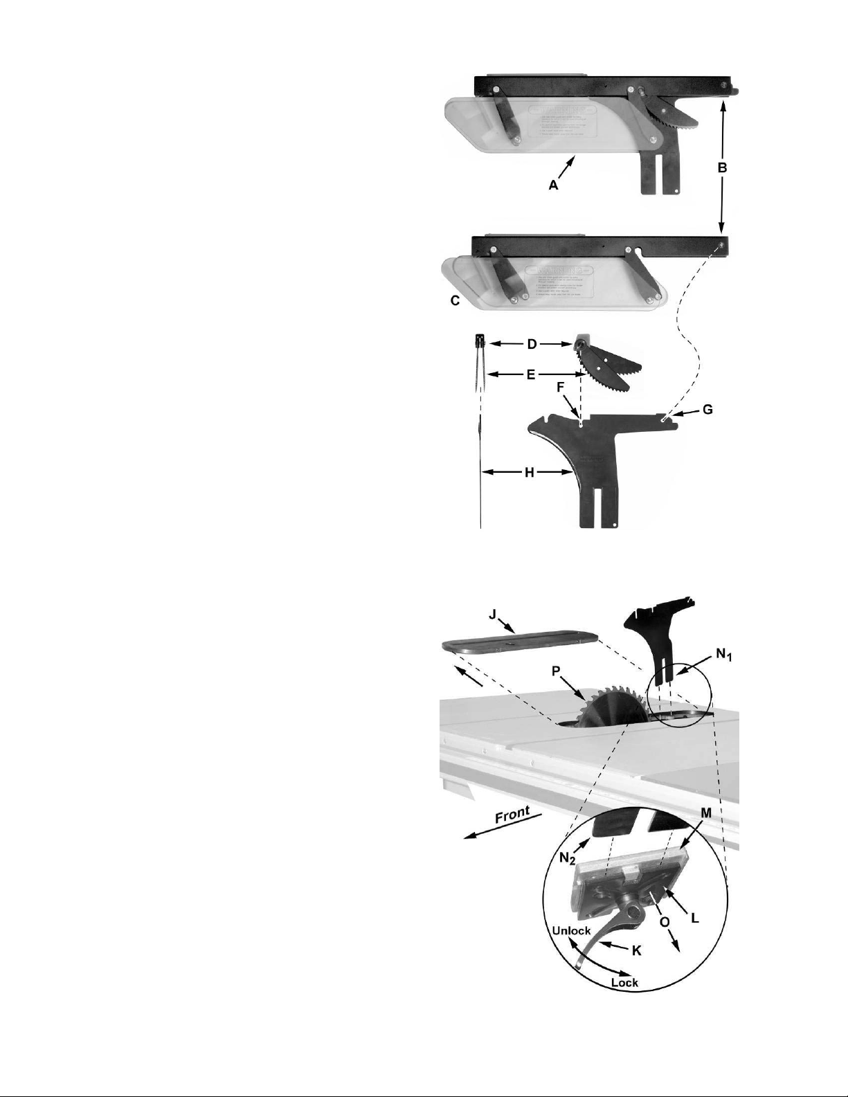
Riving Knife and Guard Instal lation
Description
Referring to Figure 7:
The complete riving knife and guard assembly is
shown in A. Before installing onto the saw, the anti-
kickback pawl (E) must be separated from the
rivi ng knife (H) as follows:
1. Pres s and hold the quick-rel ease button (D) on
the base of the anti-kickback pawl (E) and lift
the pawl to remove from the ri vi ng knife (H).
Installatio n
Referring to Figure 8:
2. Set the saw blade to the 90 degree position
and raise it all the way (refer to Handwheel
Adjustments on page 13).
3. Remove the table insert (J ) .
4. Located inside the table and accessible
through the insert opening (Figure 8 inset),
place the quick-release clamp lock handle (K)
in the unlock position.
5. The floating clamp block (L) is spring loaded
and will move away (O) from the fixed
block (M), leaving a gap.
6. Insert the bottom of the riving k nife ( N1, N2) all
the way i nto the gap betw een t he clamp blocks
(L, M); then lock the handle (K).
7. Replace the insert (J) back on the table. The
saw blade and riving knife should protrude
thro ugh the slot in the insert.
Figure 7
Referring back to Fig ure 7:
8. Attach the anti-kickback pawl (E) by pressing
and holding the quick-release button (D) and
inserting the lock pin of the pawl into the
appropriate slot ( F) on the riving knife.
9. In similar manner attach the guard (C) by
pressing and holding the quick-release button
(B) and inserting the lock pin of the guard into
the appropriate slot (G ) on the riving knife.
You should feel a snap as each piece locks in
position. Attempt to lift as a test to make sure that
they are securely locked in place.
Adjustment
The cl amp ing blocks (L, M, Fig. 8) ar e adjusted at
the factory and no fur ther adjust ment of the blade
guard and riving knife assembly should be
necessary. However, proper alignment is very
important. Before operating the table saw, read
Riving Kni fe Adjustment (p.14) to verify and follow
the adjustme nt procedure if necessary.
Figure 8
11

Mounting Rails & Extension Table
With the extension wings properly aligned, the
rail and fence assembly can now be mounted t o
the saw. Refer to the XACTA® Fence II
Commercial 30/50 Owner's Manual (Part No.
M-708950Z) for mounting instructions for the
rails, fence and optional wooden extension
table.
Switch Installation
Referring to Figure 9:
• Hardware: Switch Brace
• Tools: 8mm hex wrench, 8mm wrench
1. Remove the hex nut from the flat head
screw that secures t he left exte nsion table to
the fr ont rai l (B).
2. Place switch assembly bracket (A) behind
the front rail (B) and just inside the front
edge of the lef t extension wing.
3. Replace the hex nut, s ecuri ng t he fr ont rail,
ext ens i o n t a b l e and sw itch assembly. Handtighten o nly at this time.
4. Loosen the hex cap screw (C) a nd slide the
open tab of the switch brace (E) onto the
screw (C) and washer (D). Hand-tighten only
at this time.
5. Remove the nut and star washer (F) from
the screw at the bottom of the switch plate
on the back of the switch assembly.
6. Fasten the switch brace to the switch
bracket assembly with the star washer and
nut.
7. Align the s witch and tig ht en all hard ware .
Electrical Connections
A qualified electrician must
complete all electrical connections! Failure
to comply may result in serious injury!
The machine must be
properly grou nded while in use to pr ot ect t he
operator from electric shock! Failure to
comply ma y result in ser ious injur y !
If a pl ug is provided wit h your machine, do not
modify the plug. If it will not fit your electrical
receptacle, have a qualified electr icia n install the
proper connectio ns to meet all electrical codes.
XACTA® Saw Deluxe table saws with stock
numbers 708674 a nd 708676 are r ated at 230V
only. Saw s w it h stock number 70868 0 ar e r ated
at 230/460V, and come from the factory
prewired 230V.
To switch from 230V to 460V (machines with
stock number 708680 only):
1. Disconnect the machine from the power
source, (unplug).
2. Open the saw cabinet door.
3. Remove the cover from the motor junction
box.
4. Change wires following the diagram on the
inside of the cover.
5. Replace the cover and close the cabinet
door.
6. Replace the mag net ic on-off swit ch with par t
#JTAS10-23B (available through your
authorized JET distributor or by calling
Walter Meier (Manufacturing) Inc., at the
number on the cover).
Figure 9
Confirm power at t he site is the same as the saw
before making any electrical connections.
Review the electrical schematics on page 27-27.
The on and off s w it ch is thermall y pr ot ect ed. If
the saw motor is overloaded, or a momentary
interruption of electrical current is sensed, the
saw will s hut off. Allow a few minutes for the
saw t o cool down and reset by pushin g t he off
button.
Using extension cords can cause a loss in
power t o your mac hine. It is best if the saw is
plugged directly into an outlet on a dedicated
circuit.
12

Adjustments
Handwheel Adjustments
Referring to Figure 10:
The front handwheel (B) controls the raising and
lowering of the blade (blade height).
The si de handwheel (D) controls t he blade tilt. The
blade can be adjusted for a tilt between 90º
(vertical or a setting of 0º on the scale) and 45º left
tilt (D).
Blade height
1. Loosen the lock knob (A) on the front
handwheel (B).
2. Turn the handwheel (B) clockwise to raise and
counterclockwise to low er t he blade.
3. Tighten the lock knob (A).
Blade ti lt adj ustment
1. Loosen the lock knob (C) on the side
handwheel (D).
2. Turn the handwheel (D) counterclockwise to
adjust the saw blade down to 45º left tilt. Turn
clockwise to adj ust t he saw blade to ma ximum
of 90º.
3. After selecting the position, tighten the lock
knob (C).
Figure 10
In sert Ad justmen t
Adjust the setscrew s in the inser t w it h a 2.5mm hex
wrench (Figure 11) to ensure that the insert is
stable and flush with the table top.
M iter Gauge
Referring to Figure 12:
1. Operate miter gauge by loosening the lock
knob (A) and turni ng the mi ter body (B) t o the
desired angle. To move gauge beyond index
stops of 45° and 90°, flip down the stop (C).
2. Adjust index stops by turning one of three
adjustment screw s ( D).
Note: Always make test cut s. Do not rely solely on
miter gauge indicator marks. There are holes i n t he
miter gauge body that will allow you to mount a
wooden exte nsion fence.
Figure 11
Figure 12
13

Riving Knife Adjust ment
Lateral ali gnment
The saw blade and riving knife must be in li ne as
close as possible with each other (lateral
alignment) for the prevention of kickback. Upon
initial blade guard and riving knife installation no
further adjustme nt s ho uld be necessary. Alignment
should be c heck ed and adj ust ed, if required, af ter
each blade change.
Check the alignment as f ollows:
1. Remove the blade guard and pawl (C, E,
Fig. 7).
2. Place a straightedge (A, Fig. 13) on the table
so it rests against the blade (B, Fig 13) and
riving knife (C, Fig. 13) . Rotat e t he blade so the
top of the blade tooth touches the straightedge.
The saw blade and riving knife must be in line.
If adjustment is required:
3. Remove the table insert.
4. Loosen the lock handle (A, Fig. 14) and
remove the riving knife, making a note as to
which direction the riving knife needs to be
moved to align it with the saw blade.
5. Using a 3mm hex wrench, make adjustments
to any of the four set screws (D, Fig. 15)
accessible through openings located in the
corners of the fl oating clam p block ( E, Fig. 15).
Figure 13
Figure 14
6. If necessary, r epeat the above procedure.
Figure 15
14
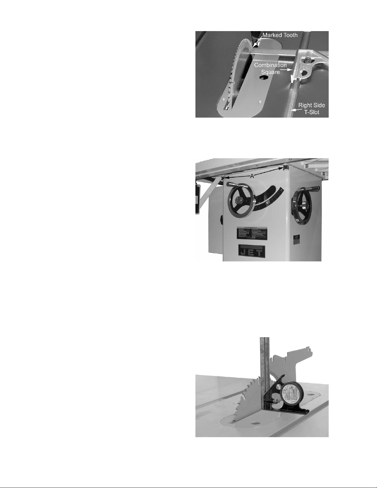
Blad e Al ignment
• Tools: 8mm hex wrench, combination square,
marker
Blade alignment with the table is adjusted at the
factor y. After a period of use, or, after moving the
saw to another location, the blade may no longer
be aligned with the table.
To check and align the blade (ref er to Figure 16):
1. Disconnect the saw fr om the power source.
2. Raise the blade guard up a way from the blade.
3. Choose a tooth on the far side of the blade
(towards the rear) and position the tooth
slightly above the table insert. Mark the tooth
with a marker . Measure t he distance from t he
side of t he blade to t he right T-slot edge using
a combination square. Make sure to measure
between the teeth not on the tooth (Figure 16).
4. Rotate the blade toward the front so that the
marked tooth is j ust abo ve the insert. Measure
the distance from the side of the blade to the
right T-slot edge. The two measurements
should be the same.
5. If they are not the same, loosen four hex
socket cap screws (A, Fig. 17) that hold the
table to t he base. Tw o are shown in Figure 17.
Figure 16
6. Make the needed adj ustments and tig hte n the
four hex socket cap screw s firmly.
7. Check the alignment once again after
tightening hardw ar e.
Adjusting 45° and 90° Posit ive Stops
The stops have bee n adjust ed at the f actor y. Aft er
a period of use, or , af t er moving the saw t o another
location, the stops may no longer be set properly.
To check and adjust the stops:
• Tools: 12mm wrench, combination square
1. Disconnect saw f r om pow er source.
2. Raise the saw blade to its maximum height
using the handwheel.
3. Set the blade at 90 degrees to the table by
turning the blade tilting handwheel clockwise
as f a r as it will go.
4. Place a combination square on the table
against the blade and check to see that the
blade is at a 9 0° a ngle to t he table, Figure 18.
Make sure square is not touching a blade
tooth.
Figure 17
Figure 18
15
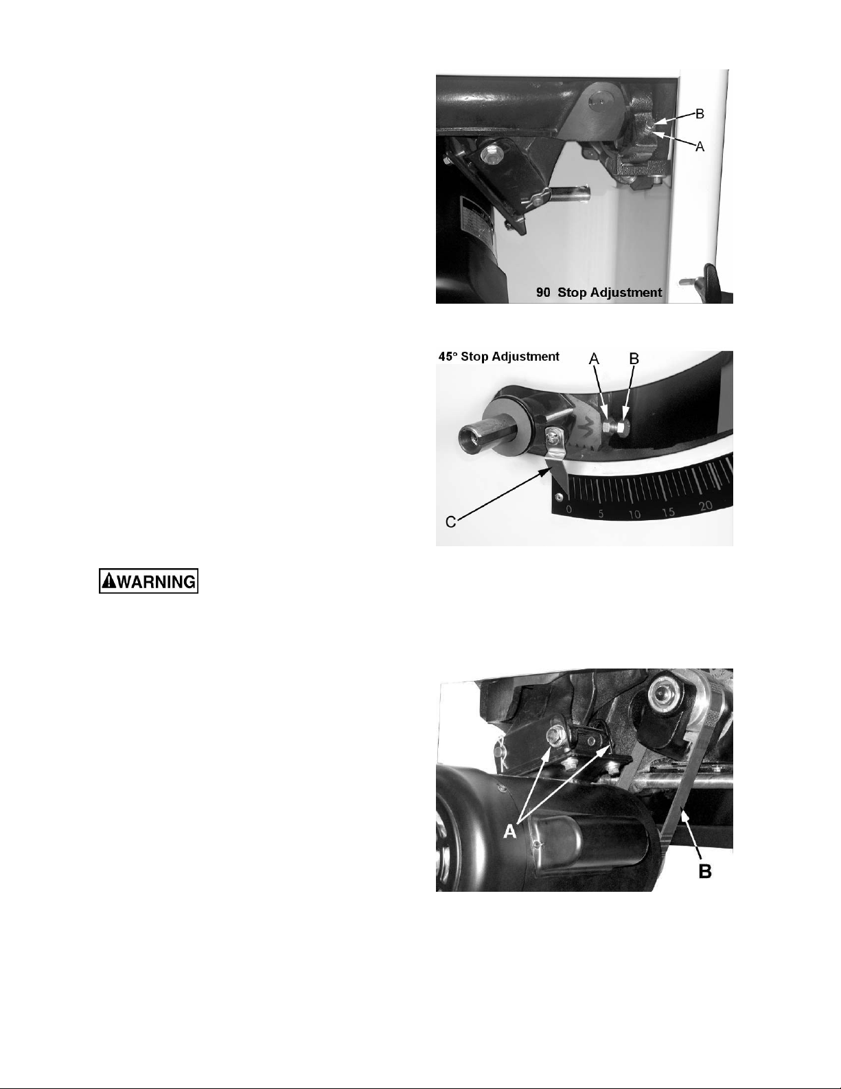
5. If blade is not at 90 degrees, open the motor
cover door, loosen lock nut (A, Fig. 19) and
turn adjusting stop screw (B, Fig. 19) on the
front trunnion in, or out. The adjusting stop
screw should stop against the front trunnion
bracket when the blade is 90° to the table.
6. Tighte n the lock nut (A, Fig. 19) .
7. Set the blade at 45 degrees to the table by
turning the blade tilting handwheel counterclockwise as far as it will go. Place a
combination square on the table against the
blade. Make sure square is not touching a
blade tooth.
8. If the blade is not 45 degrees, remove the
raising and lowering handle. Loosen lock nut
(A, Fig. 19) and turn adjusting stop screw
(B, Fig. 19) on the front tr unnio n in, or out. The
adjusting stop screw should stop against the
front tr unnion bracket w hen the blade is 45° to
the table.
9. Check the accuracy of t he po inter (C, Fig. 20)
on the angle scale and adjust, if necessary.
Assembly and adjustment of the saw are now
complete. Make sure all fasteners are tight. The
saw may now be placed into operation.
Changing the Belt
Figure 19
Figure 20
Make all machine adjustments
or maintenance with the machine unplugged
from the p ower source. Fa ilure to co mply may
cause serious injury !
Referring to Figure 21:
1. Disconnect the machine from the power
source, unplug.
2. Lower t he blade to its lowest point.
3. Loosen two hex cap bolts (A).
4. Take the tensio n off of the belt (B) by lifting up
on the motor.
5. Remove the belt from the arbor and motor
pulleys.
6. Replace and tension the belt. The weig ht of the
motor sho uld apply e noug h te nsion to the belt.
Tig hten the hex cap bolts (A).
7. C heck the belt t e nsion after t he saw has bee n
used for a few hours. Adjust as necessary.
Figure 21
16

Maintenance
Always disconne ct power to t he machine bef ore perf orming maintenance. Fai lure
to d o this may result in seriou s p e r s o n al inj u ry.
Cleaning
Note: The following maintenance schedule
assumes the saw is being used every day.
Daily:
Wipe down the table surface and grooves
with a rust preventive.
Clean pitc h and resin from the saw blade.
Weekly:
Table s urface m ust be kept clean and free of
rust for best results. Apply a coat of paste
wax to the surface to facilitate this. An
alternative is t o apply white talcum powder ,
rubbed in vigorously once a week with a
blackboard eraser ; t his will f ill casti ng pores
and form a moisture barrier. This method
provides a table top t hat is slick a nd allows
rust rings to be easily wiped from the
surface. Important also is the fact that
talcum powder will not stain wood or mar
finishes as wax pickup does.
Clean motor housing w ith compressed air.
Wipe down t he fence r ails wit h a dry s ilicon
lubricant.
Periodic:
Lubrication
Grease the tilting worm gear, raising worm
gear, castor system worm gear and the
trunnion areas with a good grade nonhardening grease.
C heck all adjustments af t er lubricating.
Miscellaneous
Rout inely c heck c ondition of the following it e ms:
Mounting bolts
Power switch
Saw blade
Blade guard assembly
Keep t he inside of the cabinet and trunnio n
area clean.
Check for excessive play in the tilting and
raising mec hanism and in the saw arbor and
re-adjust as required.
C heck for belt t ension and wear. Readj ust or
replace belt as required.
17

Troubleshooting
A
Alig
Trouble Possible Cause Solution
Saw s tops or will
not s ta rt
Overload tripped
Saw unplugged from wall or motor
Fuse blown or circuit breaker tripped
Cord damaged
llow motor to cool and reset by
pushing off sw it ch
Check all plug connectio ns
Replace fuse or reset c ircuit breaker
Replace cord
Does not make
accurate 45° or
90° cuts
Mater ial binds
blade when
ripping
Saw makes
unsatisfactory
cuts
Blade does not
come up to
speed
Saw vibrates
excessively
Stops not adjusted correctly
Angle pointer not set accurately
Miter gauge out of adjustment
Fence not aligned with blade
Warped w ood
Excessive feed rat e
Splitter not aligned wit h blade
Dull b la d e
Blade mounted backw ar ds
Gum or pitch on blade
Incorrect blade f or cut
Gum or pitch on table
Extension cord to o light or too long
Low shop voltage
Motor not wired for corr ect voltage
Stand on uneven floor
Damaged saw blade
Bad V-belts
Bent pulley
Improper motor mounting
Loose hardware
Check blade with square and adjust
stops
Check blade with square and adjust
pointer
Adjust miter gauge
Check and adjust fence
Select another piece of wood
Reduce feed rat e
Align sp litter with blade
Sharpen or replace blade
Turn blade around
Remove blade and clean
Change blade to cor r ect ty pe
Clean table
Replace wit h adequate size cord
Contact your local electric company
Refer to motor junction bo x
Reposition on flat, level surface
Replace saw blade
Replace V-belts
Replace pulley
Check and adjust motor
Tighten hardw ar e
Rip fence binds
on guide rails
Mater ial kicked
back from blade
Blade does not
raise or tilt freely
Guide rails or extension wi ng not installed
correctly
Guide of rip fence not adjusted proper ly
Rip fence out of alignment
Splitter not aligned wit h blade
Feeding stock w ithout rip f ence
Splitter not in place
Dull b la d e
Letting go of material before it is past
blade
Anti-kick back plates dull
Sawdust and debris in raising a nd t ilting
mechanisms
Re-assemble guide rails, refer to fence
manual
Adjust guides, ref er to fence manual
n rip fence with miter slot
Align sp litter with blade
Install and use rip fence
Install and use splitter (w ith guard)
Replace blade
Push material all the way past blade
before r eleasing work
Replace or sharpe n anti-kick back
plates
Clean and re-grease
18

Optional Accessories
Stock No Description
708295 Tenoning Jig
for 10” saws only:
708097 Dado Insert
708118 Universal Mobile Base
Parts
Ordering Repl acement P art s
Replacement part s ar e listed on t he fol low i ng pages. To order part s or r eac h our service department, call
1-800-274-6848, Monday through Friday (see our website for business hours, www.waltermeier.com).
Having the Model Numb er and Serial Number of y our mac hine available when you call wi ll al low us to
serve you quickly and accurately.
19

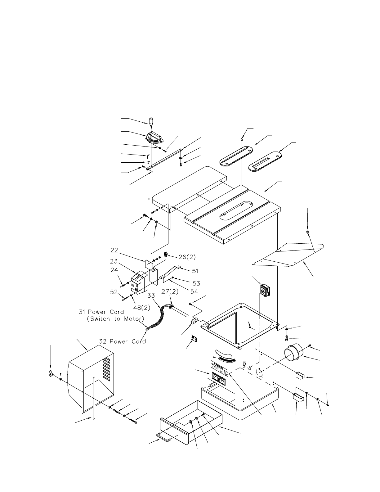
Table & Cabinet Parts List
Index No. Par t No. Description Size Qty
1 .............. JTAS10-1 ................Lock Knob .......................................................................................... 1
2 .............. JTAS10-2 ................Miter Gauge Body ............................................................................... 1
3 .............. TS-1540031 ............Hex Nut............................................................M5 ............................. 3
4 .............. JTAS10-4 ................Pointer ............................................................................................... 1
5 .............. JTAS10-5 ................Stop Link ............................................................................................ 1
6 .............. TS-1521011 ............Socket Set Screw .............................................M4x4 ......................... 1
7 .............. JTAS10-7 ................Special Pin .......................................................M3x 6 ......................... 1
8 .............. TS-2205201 ............Hex Cap Screw ................................................M5x20........................ 3
9 .............. JTAS10-9 ................Guide Bar........................................................................................... 1
10 ............ JTAS10-10 ..............Guide Washer .................................................................................... 1
11 ............ JTAS10-11 ..............Flat He ad Screw ...............................................M6x8 ......................... 1
................ JTAS10-MG ............Miter Gauge Assembly (#1-11) ............................................................ 1
12 ............ TS-0267041 ............Socket Set Screw .............................................1/4-20x3/8 .................. 6
13 ............ JTAS10L-13N ..........Table Insert ........................................................................................ 1
13A.......... 708097....................Dado Inser t - (Opti onal Access or y) ...................................................... 1
14 ............ JTAS10L-14WN .......Tabl e ................................................................................................. 1
15 ............ JTAS10L-15WN .......Exte nsion Wing .................................................................................. 2
18 ............ TS-0061051 ............He x Cap Screw ................................................7/16-14x1-1/2 ............. 6
19 ............ TS-0720101 ............Lo ck Wash er ....................................................7/16 ........................... 6
20 ............ TS-0680051 ............Flat Washer......................................................7/16 ......................... 10
22 ............ JTAS10-22W ...........Switch Plate ....................................................................................... 1
23 ............ JTAS10-23 ..............Magn etic Switch ...............................................3HP, 230V, 1 Ph ......... 1
................ JTA S10-23 A ............Magnetic Swi tch ...............................................5HP , 230V, 3 Ph ......... 1
................ JTA S10-23 B ............Magnetic Swi tch ...............................................5HP , 460V, 3 Ph ......... 1
................ JTAS12-23 ..............Magnetic Switch * ............................................5HP, 1 Ph, 230V ......... 1
24 ............ TS-081C052 ............Pan Head Screw...............................................#10-24x3/4 ................. 1
26 ............ JTAS10-26 ..............Strain Relief Bushing .......................................................................... 2
27 ............ JTAS10-27 ..............Strain Relief Bushing .......................................................................... 2
28 ............ JTAS10-28 ..............Tap Screw........................................................M5x10...................... 10
29 ............ JTAS10-29 ..............Cord Plate .......................................................................................... 1
30 ............ JTAS10L-30N ..........Identification Plate .............................................................................. 1
31 ............ JTAS10DX-31 .........Power Cord (switch to motor) .............................................................. 1
32 ............ JTA S10DX-3 2 .........P o we r Co rd ........................................................................................ 1
33 ............ JTAS10-33 ..............Power Cord Sleeve ............................................................................. 1
34 ............ JTAS10L-34 ............Tilt Scale ............................................................................................ 1
35 ............ JTA S10-3 5 ..............Wa rnin g Label .................................................................................... 1
36 ............ JTAS10-36 ..............JET Label........................................................................................... 1
38 ............ JTAS10L-38WN .......Cab inet .............................................................................................. 1
39 ............ TS-1482101 ............He x Cap Screw ................................................M6x50........................ 1
40 ............ TS-0680021 ............Flat Washer......................................................1/4 ............................. 2
41 ............ JTAS10-41 ..............Spring ................................................................................................ 1
42 ............ JTAS10-42 ..............Foam Strip ......................................................................................... 1
43 ............ JTAS10L-43WN .......Motor Cover ....................................................................................... 1
44 ............ TS-1540021 ............Nylon Insert Lock Nut ........................................M6 ............................. 1
45 ............ JTA S10-4 5 ..............H an dle ............................................................................................... 1
47 ............ TS-0210011 ............Socket Head Cap Screw ...................................7/16-14x3/4 ................ 4
48 ............ TS-0680011 ............Flat Washer......................................................3/16 ........................... 2
49 ............ JTAS10L-49WN .......Lower Panel ....................................................................................... 1
50 ............ JTAS10L-50N ..........D ust Hose Adapter ............................................................................. 1
51 ............ JTAS10-52W ...........Switch Brace Kit ** ............................................................................. 1
52 ............ TS-081C062 ............Scre w ..............................................................#10-24x1 .................... 1
53 ............ TS-0560071 ............He x Nut............................................................#10-24 ....................... 1
54 ............ TS-0733031 ............Star Washer .....................................................#10 ............................ 1
55 ............ JTAS10L-55 ............Hook .................................................................................................. 2
56 ............ TS-0680021 ............Flat Washer......................................................1/4 ............................. 6
57 ............ TS-0720071 ............Lock Washer ....................................................1/4 ............................. 6
20
58 ............ TS-0207031 ............Socket Head Cap Screw ...................................1/4-20x5/8 .................. 6
1
59 ............ JTAS10L-59 ............Hook .................................................................................................. 1
60 ............ TS-0561011 ............He x Nut............................................................1/4-20 ........................ 6
61 ............ JTAS10L-61 ............Electrical Box ..................................................................................... 1
62 ............ JTAS10L-62 ............Drawer ............................................................................................... 1
63 ............ JTAS10L-63 ............Han dle ............................................................................................... 1
64 ............ TS-1550031 ............Flat Washer......................................................M5 ............................. 2
65 ............ TS-0720051 ............Lock Washer ....................................................#10 ............................ 2
66 ............ TS-081C032 ............Pan Head Screw...............................................#10-24x1/2 ................. 2
* 10” saws with 5HP, 1Ph motor uses these parts.
** Swit ch Brace kit contains bracket, scr ew, nut, star washer, and 8mm hex wr ench.
)(
6
2
)(
3
3
4
)
3(8
9
10
11
12
13
13A
(optional)
5
6
14
28
)(
4
15
7
(
)
2
45
44
42
43
(
18 6
40
)
19(6
41
)
40
20 (6)
39
29
30
34
36
28(2)
61
60(6)
35
38
55(2)
20 (4)
47 4
56(6)
49
(
59
)
28(4)
50
58(6)
57(6)
62
63
66(2)
65(2)
64(2)
21

Trunnion & Motor Parts List
Index No. Par t No. Description Size Qty
101 .......... JTA S10L-101 ..........Arbor Nut ........................................................................................... 1
102 .......... JTAS 10-1 02 ............Arb or Flan ge ...................................................................................... 1
104 .......... JTA S10L-104N ........Arbor with Flange ............................................................................... 1
105 .......... JTA S 10-105 ............K e y .................................................................M5x4 4........................ 2
106 .......... BB- 6203ZZ ..............Ball Bearing......................................................6203ZZ ...................... 2
107 .......... JTA S 10-107 ............Wa ve Wash e r..................................................................................... 4
108 .......... JTA S 10-108 ............Rear Bea ring Load Spacer .................................................................. 2
108-1 ....... JTAS10DX-1 0 8........F ro nt Bearing Load Spacer.................................................................. 1
109 .......... TS- 0267041 ............Socket Set Screw .............................................1/4-20x3/8 ................ 10
110 .......... JTA S 10-110N ..........Arb o r Pulley ....................................................................................... 1
111 .......... TS- 0209081 ............Socket Head Cap Screw ...................................3/8-16x1-3/4 ............... 1
112 .......... JTA S 10DX-11 2........K e y ..................................................................1/4x1/4x 4 5 ............... .. 1
113 .......... TS- 0720091 ............Lock Washer ....................................................3/8 ........................... 10
114 .......... JTA S 10DX-11 4........A rb o r Bra c ke t ..................................................................................... 1
115 .......... JTA S 10-115 ............S p an ner N ut ....................................................................................... 1
116 .......... JTA S10L-116 ..........Nut ..................................................................5/8 ............................. 1
117 .......... JTAS 10-1 17 ............Sp rin g P in ........................................................M6x 5 0........................ 1
118 .......... JTA S 10-118 ............K e y ..................................................................1/4x1/4x 2 -5 /1 6 ......... ... 1
119 .......... TS- 0680051 ............Flat Washer......................................................7/16 ........................... 2
120 .......... TS- 0091031 ............Hex Cap Screw ................................................7/16-14x1 ................... 2
121 .......... JTA S 10DX-12 1........S h a ft .................................................................................................. 1
122 .......... JTA S 10-122 ............Mo to r Bra c k et ..................................................................................... 1
123 .......... JTA S 10-123 ............P in ..................................................................................................... 1
124 .......... JTAS 10-1 24 ............Sp rin g C lip ......................................................................................... 2
125 .......... JTA S10L-125N ........Poly V-Belt .......................................................260J .......................... 1
126 .......... JTA S 1 0D X-126........Motor Mo u ntin g Bra c k e t ...................................................................... 1
127 .......... JTA S 10-127N ..........Motor Pull e y ....................................................................................... 1
128 .......... TS- 0680031 ............Flat Washer......................................................5/16 ......................... 10
129 .......... TS- 0720081 ............Lo ck Wash er ....................................................5/16 ........................... 9
130 .......... TS- 0081031 ............Hex Cap Screw ................................................5/16-18x3/4 ................ 4
131 .......... JTA S 10DX-13 1N .....Motor ...............................................................3HP, 1Ph , 230V only... 1
................ JTA S10DX- 131C .....Motor ...............................................................5H P, 1Ph , 230V only... 1
................ JTA S10DX- 131A .....Moto r ...............................................................5H P, 3Ph, 230/460V ... 1
................ JTA S10DX- 131CS ...Centrifugal Switch Assembly (not shown) ............................................. 1
................ JTAS10-131D ..........Fan Cover (not shown) ........................................................................ 1
................ JTA S10-131F ..........Motor Fan (not show n) ........................................................................ 1
................ C-600125 ................Start Capacitor ( not shown) ...............................3 HP, 1Ph motor .......... 1
................ C-040250 ................Run Capacitor ( not shown) ................................3 HP, 1Ph motor .......... 1
................ JTA S10-1315B ........Start Capacitor (not shown) ...............................5 HP, 1Ph motor .......... 1
................ JTA S10-1315A ........Run Capacitor (not shown) ................................5HP, 1Ph motor .......... 1
132 .......... TS- 0209071 ............Socket Head Cap Screw ...................................3/8-16x1-1/2 ............... 6
133 .......... JTA S 10DX-13 3........R e a r Trunnion Br ack et ........................................................................ 1
134 .......... TS- 0561031 ............Hex Nut............................................................3/8-16 ........................ 5
135 .......... TS- 0209051 ............Socket Head Cap Screw ...................................3/8-16x1..................... 4
136 .......... JTAS 10-1 36 ............Sp rin g P in ........................................................M8x 2 5........................ 4
137 .......... TS- 0561081 ............Hex Nut............................................................3/4-10 ........................ 1
138 .......... JTA S 10-138 ............F iber Washer...................................................................................... 4
139 .......... JTA S 10DX-13 9........R e a r Trunnion ................................................................................... 1
140 .......... JTA S 10-140 ............Rear Bu shing ..................................................................................... 2
140-1 ....... JTAS10DX-1 4 0........F ro nt Bushing ..................................................................................... 1
141 .......... JTA S 10DX-14 1........Yok e .................................................................................................. 1
142 .......... TS- 0270011 ............Socket Set Screw .............................................5/16-18x1/4 ................ 4
143 .......... JTA S 10-143 ............Collar ................................................................................................. 2
144 .......... JTA S 10DX-14 4........S h a ft .................................................................................................. 1
145 .......... JTAS 10-1 45 ............Sp rin g P in ........................................................M5x 3 0........................ 2
146 .......... JTAS10-146 ............Worm (Left thread).............................................................................. 2
146-1 ....... JTAS10DX-146........Worm (Rig ht thread) ........................................................................... 1
147 .......... JTA S 10-147 ............L o c k Pin ............................................................................................. 4
148 .......... JTA S 10-148 ............K e y ..................................................................M5x35........................ 2
22

Trunnion & Motor Parts List
Index No. Par t No. Description Size Qty
149 .......... TS- 0208041 ............Socket Head Cap Screw ...................................5/16-18x3/4” ............... 4
150 .......... JTA S10L-150N ........Dust Deflector .................................................................................... 1
151 .......... JTA S10L-151N ........Hose Cla mp ....................................................................................... 2
152 .......... JTA S 10DX-15 2........Fr o nt Trunnion .................................................................................... 1
................ JTA S10DX-TA .........Trunnion Assembly (#113, 135, 136, #139 through #141 and # 152) ...... 1
153 .......... TS- 0051021 ............Hex Cap Screw ................................................5/16-18x5/8 ................ 2
154 .......... TS- 0561021 ............Hex Nut............................................................5/16-18 ...................... 2
155 .......... JTA S 10-155A ..........Lock Knob .......................................................................................... 2
156 .......... JTA S 10-156 ............F iber Washer...................................................................................... 2
157 .......... TS- 0208061 ............Socket Head Cap Screw ...................................5/16-18x1 ................... 2
158 .......... JTA S 10DX-15 8........Fr o nt Trunnion Bracket ....................................................................... 1
159 .......... JTA S 10-159 ............Hand Wh ee l Handle ............................................................................ 2
160 .......... JTAS 10-1 60 ............Han d Wheel .................................................................................. ..... 2
161 .......... JTA S 10-161 ............S h ield Pla te ........................................................................................ 1
162 .......... TS- 0813022 ............Round Head Screw ...........................................1/4-20x3/8 .................. 1
163 .......... JTA S 10-163 ............P o inter ............................................................................................... 1
164 .......... JTA S 10-164 ............P o inter Brac k e t ................................................................................... 1
165 .......... TS- 081C102 ............Pan Head Scr ew ...............................................#10-24x2 .................... 2
166 .......... JTA S 10DX-16 6........Guide Bloc k........................................................................................ 1
167 .......... TS- 0680041 ............Flat Washer......................................................3/8 ............................. 1
169 .......... JTA S 10DX-16 9........Tilt Shaft ..................................................................................... ....... 1
170 .......... JTA S10L-170 ..........Wren ch .............................................................................................. 1
171 .......... JTA S10L-171 ..........Hose ................................................................700mm ...................... 1
172 .......... JTA S10L-172 ..........Plate .................................................................................................. 1
173 .......... TS- 0208041 ............Socket Head Cap Screw ...................................5/16-18x3/4 ................ 3
174 .......... JTA S10L-174 ..........Chip Pl ate .......................................................................................... 1
175 .......... TS- 0680011 ............Flat Washer......................................................3/16 ........................... 3
176 .......... TS- 0720051 ............Lock Washer ....................................................#10 ............................ 3
177 .......... JTA S10L-177 ..........Hex Cap Bolt ....................................................#10-24x3/8 ................. 3
178 .......... JTA S10L-178 ..........Special Screw .................................................................................... 1
179 .......... JTA S10L-179A ........Arbor Lock Insert Assembly (#179-1through #179-5) ............................. 1
179-1 ....... JTAS10L-179-1 .......Arbor Lock Insert ..............................................Ø8 ............................. 1
179-2 ....... JTAS10L-179-2 .......Sprin g ................................................................................................ 1
179-3 ....... JTAS10L-179-3 .......Insert Bracket ..................................................................................... 1
179-4 ....... TS-1502051 ............Socket Head Cap Screw ...................................M5 x 20 ...................... 2
179-5 ....... TS-1521041 ............Socket Set Screw .............................................M4 x 10 ...................... 1
180 .......... JTA S10L-180 ..........Spring ................................................................................................ 1
181 .......... TS- 0640071 ............Nylon Insert Lock Nut ........................................1/4-20 ........................ 3
182 .......... JTA S10L-182N ........Sp acer ............................................................................................... 2
183 .......... JTA S10L-183 ..........Guide Bracket .................................................................................... 1
184 .......... TS- 0245051 ............Flat He ad Socket Screw ....................................1/4-20x1..................... 2
185 .......... JTA S10L-185 ..........Special Screw .................................................................................... 1
186 .......... JTA S10L-186 ..........Extensio n Suppor t Plate ...................................................................... 1
187 .......... TS- 1541021 ............Nylon Insert Lock Nut ........................................M6 ............................. 1
188 .......... JTA S10L-188 ..........Plate .................................................................................................. 1
189 .......... JTA S10L-189A ........Riving Knife Extension Plate ................................................................ 1
190 .......... TS- 1513021 ............Flat He ad Socket Screw ....................................M5x12........................ 2
191 .......... JTA S10L-191 ..........Clamping Block .................................................................................. 1
192 .......... JTA S10L-192 ..........Spring ................................................................................................ 1
193 .......... JTA S10L-193 ..........Clamping Block .................................................................................. 1
194 .......... TS- 1514031 ............Flat He ad Socket Screw ....................................M6X20 ....................... 2
195 .......... JTA S10L-195 ..........Locking Handle................................................................................... 1
196 .......... TS- 1541031 ............Nylon Insert Lock Nut ........................................M8 ............................. 1
197 .......... JTA S10L-197 ..........Spring Shim Ring................................................................................ 1
198 .......... JTA S10L-198 ..........C- Rin g .............................................................S5 2............................ 1
23

Trunnion & Motor Assembly Drawing
24

Blad e Guard Part s and Assembly
Index No. Par t No. Description Size Qty
1 .............. JTAS10L-301 ..........Riving Knife ....................................................................................... 1
................ JTA S10DX-BGA ......Blade Guard Assembly ( I ndex #2 thru #16, #21, #22)............................ 1
2 .............. PM2000-302............Bushing.............................................................................................. 2
3 .............. JTAS10L-303 ..........Blade G uar d Body .............................................................................. 1
4 .............. JTAS10L-304 ..........Blade G uar d Side S hield ..................................................................... 2
5 .............. PM2000-305............Linking Plate ...................................................................................... 4
6 .............. TS-1550041 ............Flat Washer......................................................M6 ............................. 8
7 .............. TS-1514021 ............Flat Head Socket Screw ....................................M6x16........................ 8
8 .............. PM2000-308............Front Shield........................................................................................ 1
9 .............. PM2000-309............Bushing.............................................................................................. 1
10 ............ PM2000-310............Top Sight Shield ................................................................................. 1
11 ............ TS-1541021 ............Nylon Insert Lock Nut ........................................M6 ............................. 8
12 ............ TS-081B012 ............Pan Head Screw...............................................#8-32x1/4 ................... 2
13 ............ PM2000-313............Roll Pin ............................................................5x25 .......................... 1
14 ............ PM2000-314............Roll Pin ............................................................5x12 .......................... 2
15 ............ PM2000-315............Lock Pin ............................................................................................. 1
16 ............ PM2000-316............Roll Pin ............................................................4x28 .......................... 1
................ PM2000-AKPA ........Anti-K ickback Paw l Asse mbly (Inde x #17 thru #22) .............................. 1
17 ............ PM2000-317............Anti-Kickback Pawl ............................................................................. 2
18 ............ PM2000-318............Pawl Base .......................................................................................... 1
19 ............ PM2000-319............Flange ............................................................................................... 2
20 ............ PM2000-320............Lock Pin ............................................................................................. 1
21 ............ PM2000-321............Sprin g ................................................................................................ 2
22 ............ PM2000-322............E-Clip...............................................................E5.............................. 2
25

Wiri ng Diagrams
3HP/5HP , 230V , 1Phase
26
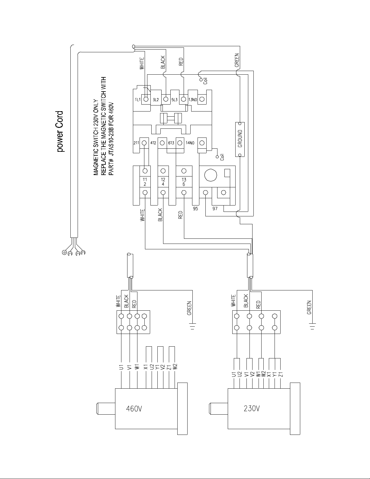
5HP, 230V , 3 P hase
27

WALTER MEIER (Manuf acturing) Inc.
427 New Sanford Road
LaVergne, TN 37086
Phone: 800-274-6848
www.waltermeier.com
28
 Loading...