


This .pdf document is bookmarked
Operating Instructions and Parts Manual
10" Compound Miter Saw
Benchtop Series – Model No. JMS-10CMS
JET
427 New Sanford Road
LaVergne, Tennessee 37086 Part No. M-707100
Ph.: 800-274-6848 Revision B2 11/2014
www.jettools.com Copyright © 2014 JET

Warranty and Service
JET warrants every product it sells against manufacturers’ defects. If one of our tools needs service or repair, please contact
Technical Service by calling 1-800-274-6846, 8AM to 5PM CST, Monday through Friday.
Warranty Period
The general warranty lasts for the time period specified in the literature included with your product or on the official JET
branded website.
• JET products carry a limited warranty which varies in duration based upon the product. (See chart below)
• Accessories carry a limited warranty of one year from the date of receipt.
• Consumable items are defined as expendable parts or accessories expected to become inoperable within a
reasonable amount of use and are covered by a 90 day limited warranty against manufacturer’s defects.
Who is Covered
This warranty covers only the initial purchaser of the product from the date of delivery.
What is Co vered
This warranty covers any defects in workmanship or materials subject to the limitations stated below. This warranty does not
cover failures due directly or indirectly to misuse, abuse, negligence or accidents, normal wear-and-tear, improper repair,
alterations or lack of maintenance. JET woodworking machinery is designed to be used with Wood. Use of these machines in
the processing of metal, plastics, or other materials may void the warranty. The exceptions are acrylics and other natural items
that are made specifically for wood turning.
Warranty Limitations
Woodworking products with a Five Year Warranty that are used for commercial or industrial purposes default to a Two Year
Warranty. Please contact Technical Service at 1-800-274-6846 for further clarification.
How to Get Technical Support
Please contact Technical Service by calling 1-800-274-6846. Please note that you will be asked to pr ovi d e pr o of of ini tial
purchase when calling. If a product requires further inspectio n , the Technical Service r epr esent a tive will explain an d assist
with any additional action needed. JET has Authorized Service Centers located throughout the United States. For the name of
an Authorized Service Center in your area call 1-800-274-6846 or use the Service Center Locator on the JET website.
More Information
JET is constantly adding new products. For complete, up-to-date product information, check with your local distributor or visit
the JET w ebsite.
How State Law Appli es
This warranty gives you specific legal rights, subject to applicable state law.
Limitations on This Warranty
JET LIMITS ALL IMPLIED WARRANTIES TO THE PERIOD OF THE LIMITED WARRANTY FOR EACH PRODUCT.
EXCEPT AS STATED HEREIN, ANY IMPLIED WARRANTI ES OF MERCHANTABILITY AND FITNESS FOR A PARTICULAR
PURPOSE ARE EXCLUDED. SOME STATES DO NOT ALLOW LIMITATIONS ON HOW LONG AN IMPLIED WARRANTY
LASTS, SO THE ABOVE LIMITATION MAY NOT APPLY TO YOU.
JET SHALL IN NO EVENT BE LIABLE FOR DEATH, INJURIES TO PERSONS OR PROPERTY, OR FOR INCIDENTAL,
CONTINGENT, SPECIAL, OR CONSEQUENTIAL DAMAGES ARISING FROM THE USE OF OUR PRODUCTS. SOME
STATES DO NOT ALLOW THE EXCLUSION OR LIMITATION OF INCIDENTAL OR CONSEQUENTIAL DAMAGES, SO THE
ABOVE LIMITATION OR EXCLUSION MAY NOT APPLY TO YOU.
JET sells through distributors only. The specifications listed in JET printed materials and on official JET website are given as
general information and are not binding. JET reserves the right to effect at any time, without prior notice, those alterations to
parts, fittings, and accessory equipment which they may deem necessary for any reason whatsoever. JET
are not sold in Canada by JPW Industries, Inc.
Product Listing with Warranty Period
90 Days – Parts; Consumable items; Light-Duty Air Tools
1 Year – Motors; Machine Accessories; Heavy-Duty Air Tools; Pro-Duty Air Tools
2 Year – Metalworking Machinery; Electric Hoists, Electric Hoist Accessories; Woodworking Machinery used
for industrial or commercial purposes
5 Year – Woodworking Machinery
Limited Lifetime – JET Parallel clamps; VOLT Series Electric Hoists; Manual Hoists; Manual Hoist
Accessories; Shop Tools; Warehouse & Dock products; Hand Tools
NOTE: JET is a division of JPW Industries, Inc. References in this document to JET also apply to JPW Industries, Inc., or any
of its successors in interest to the JET brand .
®
branded products
2

Table of Contents
Warranty and Servic e .................................................................................................................................... 2
Table of Contents .......................................................................................................................................... 3
Warnings ....................................................................................................................................................... 4
Compound Miter Saw Saf ety .......................................................................................................................... 6
Introduction .................................................................................................................................................... 7
Specifica tio ns ................................................................................................................................................ 7
Cutting Capacity ............................................................................................................................................ 7
Electrical ........................................................................................................................................................ 8
Feature s ........................................................................................................................................................ 9
Shipping Contents ....................................................................................................................................... 10
Assembly ..................................................................................................................................................... 11
Adjustments ................................................................................................................................................. 14
Operation..................................................................................................................................................... 18
Crown Molding Chart ................................................................................................................................... 23
Maintenance ................................................................................................................................................ 24
Troubleshooting – Motor .............................................................................................................................. 25
Troubleshooting – Operation ........................................................................................................................ 25
Parts ............................................................................................................................................................ 26
Wiring Diagram ............................................................................................................................................ 33
The specificati ons in t his manual are giv en as general inf ormation and are not bindi ng. JET reserv es the right
to effect, at any time and without prior notice, changes or alterations to parts, fittings, and accessory
equipment deemed nec essary for any reason whatsoever.
3

Warnings
1. Read and understand the ent ire owners' manual bef or e attempting assembly or operation.
2. Read and understand the warnings po sted on the m achine and i n thi s manual. Fail ure to comply wit h
all of these warnings m ay cause seriou s i njury.
3. Replace the warning labels if they become obscured or remov ed.
4. This saw is de si gned and intended for use by properly tr ained and experienced personnel only. If y ou
are not famili ar with the proper and saf e operati on of a compound mit er saw, do not use until proper
training and knowledge have been obtained.
5. Do not use this saw for other than its intended use. If used for other purposes, J E T disclaims any real
or implied warranty and holds itself harmless f r om any injury that m ay result from that use.
6. Always wear approv ed safety glasses/face shields whil e using this miter saw. Everyday eyeglasses
only have impact resi stant lenses; they are not saf ety glasses.
7. Bef ore operati ng this saw, remov e tie, rings, watche s and other j ewelry, and roll sleeves up past the
elbows. Remove all loose clothing and confine long hair . Non-slip footwear or anti - skid floor stri ps are
recommended. Do not wear gloves.
8. Wear ear protector s (plugs or muffs) during ext ended peri ods of oper ation.
9. Some dust created by power sanding, sawing, grinding, drilling and other construction activities
contain chemi cals known to cause cancer , bir th defects or other r eproductiv e harm . Some exampl es
of these chemic als are:
• Lead from lead based paint.
• Crystalli ne sil ic a from bricks, cement and other m asonry pr oduc ts.
• Arsenic and chromium from chemically treated lum ber .
Your risk of exposure varies, depending on how often you do this type of work. To reduce your
exposure to these chemicals, work in a well-ventilated area and work with approved safety
equipment, such as face or dust masks that are specifically designed to filter out microscopic
particles.
10. Do not operate this machine while tired or under the influence of dr ugs, alcohol or any medication.
11. M ak e certain the switch is i n the OFF position before connecting the machine to the power supply.
12. M ak e certain the machine is proper ly grounded.
13. M ak e all machine adjustm ents or maintenance with the machine unplugged from the power source.
14. Remove adjusting keys and wrenches. Form a habit of checking to see that keys and adjusting
wrenches are removed from the machine before turning it on.
15. Keep safety guards in place at all times when the machine is in use. If removed for maintenance
purposes, use extreme caution and replace the guar ds immediately.
16. M ak e sure this machine is firmly secured to the floor or bench befor e use.
17. Check damaged parts. Before further use of the machine, a guard or other part that is damaged
should be carefully checked to determine that it will operate properly and perform its intended
function. Chec k for alignment of moving par ts, binding of moving parts, breakage of parts, mounting
and any other condi ti ons that m ay affect its operati on. A guard or ot her part that i s damaged should
be properly repaired or replaced.
18. P r ovide for adequate space surrounding work area and non-glare, overhead lighting.
19. K eep the floor around the m achi ne cl ean and free of scrap material, oil and grease.
4

20. Don' t use in dang er ous environm ent. Don't use power tools i n damp or wet locations, or expose them
to rain. Keep work area well lighted.
21. K eep v isitors a safe distanc e fr om the work area. Keep ch ildren away.
22. M ak e your workshop child proof wi th padlocks, master switches or by rem ov ing starter keys.
23. Giv e your work undivi ded attention. Looki ng around, carryi ng on a conversati on and “horse-play” ar e
careless acts that can r esul t in serious injury.
24. Maintain a balanced stance at all times so that you do not fall or lean agai nst the blade or other
moving part s. Do not over r eac h or use excessive force to perform any m ac hine oper ation.
25. Use the ri ght t ool at the cor rect speed and feed r ate. Do not for ce a tool or attachm ent to do a j ob for
which it was not designed. T he ri ght tool will do the job better and safer.
26. Use rec om mended accessories; i mproper accessories may be hazardous.
27. Maintain tools with care. Keep saw blades sharp and clean for the best and safest performance.
Follow instructions for lubricating and changing accessories.
28. Disconnect tools before servicing and when changing ac c essories such as blades.
29. M ak e sure the work piece is securel y att ac hed or cl amped to the table.
30. Turn off the machine before c leaning. Use a brush or compressed air t o r emove chips or debr is — do
not use your hands.
31. Do not stand on the machine. S eri ous i njury could occur if the machine ti ps over.
32. Never leave the m ac hine r unning unattended. Tur n the power off and do not leav e the mac hine until it
comes to a complete stop.
33. Remove loose item s and unnecessary work pieces from the area before starting the machine.
Familiariz e you rself with the following safety no ti ces used in this manual:
This means that if precautions are not heeded, it may result in minor injury and/or
possible machine damage.
This means that if precauti ons are not heeded, it may result in serious injury or possibly
even death.
5

Compound Miter Saw Safety
Specific safety instructions for this compound miter saw:
1. Do not operate the miter saw until it is completely assembled and installed according to these
instructions.
2. If you are not thoroughly familiar with the operation of miter saws, seek guidance from your
supervisor, instructor or other qualified person.
3. Always hold the work firmly against the fence and t able.
4. Do not perform any operat ion free hand (use clamp wherev er possible).
5. Keep hands out of the path of the saw blade. If the workpiece you are cutting would cau se your
hands to be within 6-3/4 in. of the saw blade, the workpiece should be clamped in place before
making the cut.
6. Be sure the blade is sharp, runs f r eely and is free of vibration.
7. Allow the motor to com e up to full speed before starting a cut.
8. Keep the motor air slot s clean and free of chips or dust.
9. Always make sure all handl es are tight before c utting, ev en if the table is positi oned in one of the
positive stops.
10. B e sure both the blade and the coll ar are clean and the arbor bolt is tightened securely.
11. Use onl y blade collars specified for your saw.
12. Never use blades larger in diam eter than 10 inches.
13. Never apply lubricants to the blade when it is running.
14. A lways check the blade for crack s or damage before operation. Replace a crac k ed or dam aged blade
immediately.
15. Never use blades recommended for operation at less than 4800 RPM.
16. A lways keep the blade guards in place and use at all times.
17. Never reach around the saw blade.
18. M ak e sure the blade is not contacting the workpiece bef or e the switc h is tur ned ON.
19. Impor tant : Aft er com pleting t he cut , rel ease the t ri gger and wait for the bl ade to stop before ret urni ng
the saw to the raised position.
20. Make sure the blade has come to a complete stop before removing or securing the workpiece,
changing the workpi ec e angle or changing the angle of the blade.
21. Nev er cut metal s or masonry product s wit h thi s tool . Thi s mit er saw is designed for use on wood and
wood-lik e pr oduc ts.
22. Never cut small pieces. If the workpiec e being cut would cause your hand or fingers to be within 6- 3/4
in. of the saw blade the workpiece is too small.
23. P r ovide adequate support t o the sides of the saw table for long work pieces.
24. Never use the miter saw in an area with flammable liquids or gases.
25. Never use solvents to c lean p lastic pa rts. S o lvents cou ld po s s ibly dissolve o r o therw ise da mage the mater ial.
26. S hut off the power befor e servici ng or adjusting the tool.
27. Disconnect the saw from the power source and clean the machine when finished using.
28. M ak e sure the work area is clean bef or e leav ing the machine.
29. Should any part of your miter saw be missing, damaged, or fail in any way, or any electrical
component f ail to perform properly, lock the switch and remov e the plug from the power suppl y outlet.
Replace missing, damaged, or failed parts before resuming operation.
6

Introduction
This manual is prov ided by JET covering t he safe op eration and maint enance procedures for the J ET
Model JMS-10CMS Compound Miter Saw with laser. This manual contains instructions on installation,
safety prec autions, general operating pr ocedures, maintenance i nstructi ons and parts breakdown. Thi s
machine has been designed and constructed to provide years of trouble free operation if used in
accordance with instructions set forth in this manual. If there are any questions or comments, please
contact eit her y our l oc al suppli er or JET. JET can also be reached at our web site: www.jettools.com.
Specifications
Model Number ....................................................................................................................... JMS-10CMS
Stock Number................................................................................................................................ 707100
Motor ............................................................................................................................... 120V, 60Hz, 15A
No Load Speed (Arbor) ............................................................................................................... 4800RPM
Motor Arbor Shaft Size ........................................................................................................................ 5/8"
Blade .................................................................................................................... 10", 40T, carbide tipped
Blade Arbor Size ................................................................................................................................. 5/8"
Net Weigh t ..................................................................................................................................... 33.3 lb.
The above specifications were current at the time this manual was published, but beca us e of our pol ic y of
continuous impr ovement , JET reserves the r ight to change specifications at any t ime and without prior
notice, without incurring obligati ons.
Cutting Capacity
Cutting Capacit y
Cut Type Miter Angle Bevel Angle Cutting Capacity
Cross Cut 0º 0º 2-5/8" x 5-1/2" 3-1/2" x 3-1/2"
Miter 45º Right & Left 0º 2-5/8" x 3-1/2" 3-1/2" x 2"
Bevel 0º 45º Left 1-1/2" x 5-1/2" 2" x 3-1/2"
Compound Cut 45º Right & Left 45º Left 1-1/2" x 3-1/2" 2" x 2"
Vertical Capacity (Base
Board)
-- -- 4"
with 3/4"
Auxiliary Fence
Read and understand the entire contents of this manual before attempting
assembly or operat io n! Failure to comply may cause serious inju ry!
7

Electrical
Extens ion Cords
Power Supply and Motor
Specifications
The AC motor used in this saw is a universal,
nonreversible type (see Motor in the Specifica-
tions section on page 7).
To avoid electrical hazards,
fire hazards, or damage to the machine, use
proper circuit protection. Your saw is wired
at the facto ry for 120V operati on. Conn ect to
a 120V, 15 Amp circui t and use a 15 amp time
delay fuse o r circu it breaker. If power co rd is
worn or cut, or damaged in any way, have i t
replaced immediately to avoid shock or fire.
Electrical Requirements
This machine is double insulated to provide a
double thickness of insulation between the user
and the machine's electrical system. A ll exposed
metal part s are isolat ed from the inter nal metal
motor component s with pr otective insulati on.
This saw has a plug that looks like the one
shown in Figure A.
Make sure your extension cord is in good
condition. When using an extension cord, be
sure to use one heavy enough to carry the
current your m achine will dr aw. An undersized
cord will cause a drop in the line voltage
resulting in power loss and overheating. The
table below shows the correct size to use
depending on the cord length and nameplate
ampere rati ng. If in doubt, use the next heavier
gauge. Remember, the smaller the gauge
number, the heavier the cord.
Cord Length AWG
00 – 25ft 016
25 – 50ft 014
Important: Make certain the receptacle in
question is properly grounded. If you are not
sure, have a registered electrician check the
receptacle.
Figure A
To reduce the risk of electrical shock, this saw
has a polarized plug (one blade is wider than the
other). This plug will fit in a polarized outlet only
one way; if the plug does not fit fully in the outlet,
reverse the pl ug. If it still does not fit , contact a
qualified electrician to install the proper outlet.
Do not change the plug i n any way.
Double insulation does not take the place of
normal safety precautions when operating this
tool.
To avoid electroc ution:
1. Use only identical replacement parts when
servicing a tool with double insulation.
Servicing shoul d be per formed by a qualified
technician.
2. Do not use power tools in wet or damp
locations or expose them to rain or snow.
8

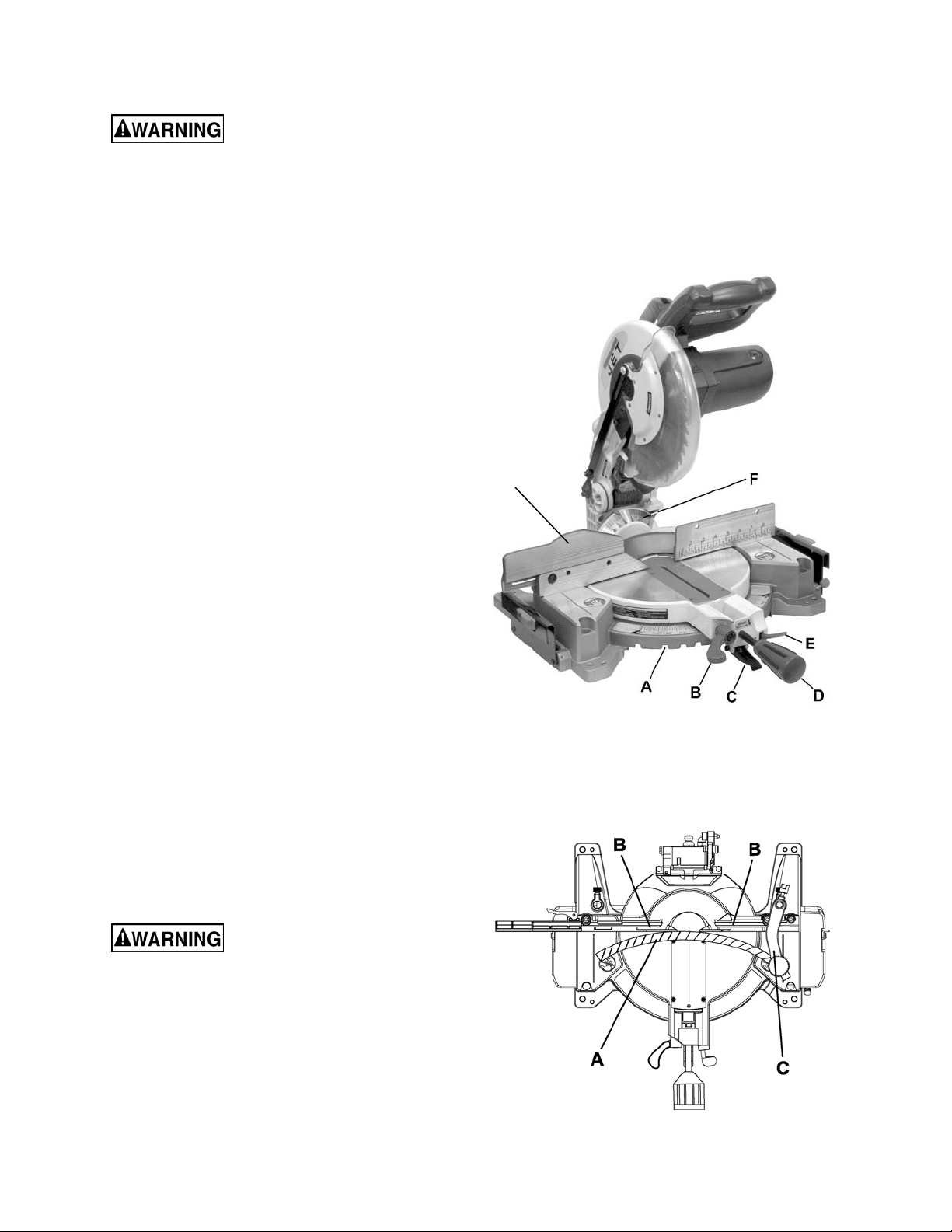
Features
9
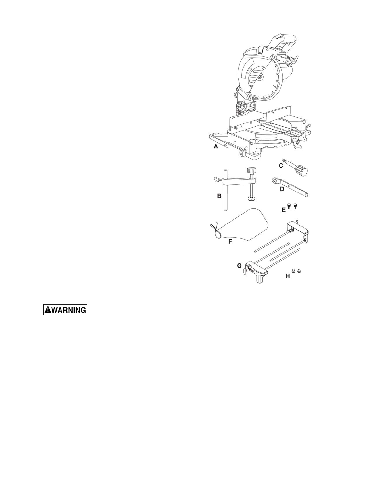
Shipping Contents
Unpacking
1. Remove the contents from the shipping
container.
2. Compare the contents of the shipping
container with the list found below. Make
certain that all items are accounted for
before discarding any packing material.
Report any shortages or damage to your
JET distri butor.
Contents of the Shipping Container
A Miter Saw (1)
B Hold-down Clamp (1)
C Miter Handle (1)
E Lock Knob (2)
F Dust Bag (1)
G Extension Table (2)
H Screw (2)
-- Owner’s Manual ( 1)
-- Warranty Registration Card
Tools Supplied for Assembly
D Blade Wrench
Tools not inc l uded
00Adjustable Wrench
006mm Hex Wrench
00Crosspoint Scr ewdriver
00Combination Wrench
Read and understand all
assembly instructions before attempting
assembly! Failure to comply may cause
serious injury!
Contents of Shipping Container
10

Assembly
Releasing the Cutting Head
When not in use, lock the
cutting head in the down position. Failure to
comply can cause serious injury or damage
equipment.
Refer to Figure 1.
Unlocking
1. Push down on the switc h handle (A).
2. Pull out the hold-down latch (B).
3. Raise the cutti ng head to the up position.
Locking
Note: When not i n use, l ock the cut ting head i n t he
down position.
1. Push the cutting head down.
2. Press the hold-dow n latch (B) in to lock.
Important: Always use the carryi ng handles when
lifting or moving to avoid damage to the machine.
Installing the Extension Table
Referring to figure 2:
1. Loosen the extension table lock knob (E).
2. Place the extension mounting tube (D) into the
two holes provi ded in the miter saw base.
3. From underneath the saw, i nsert one screw (B)
into the mounting tube hole (4) and tighten.
4. Slide the extension table to desired position
and tighten the extension table lock knob (E).
5. Install the right extension table in the same
manner.
Installing the Miter Handle
Figure 1
Figure 2
Thread the miter handle (F, Fig. 2) into the hole
located at the front of the miter table.
Installing the Dust Bag
Referring to Fi gur e 3:
1. Squeeze the meta l collar wings of the dust bag (A).
2. Place the dust bag neck opening around the
exhaust port ( B), and rel ease the c ollar wings.
To empty t he dust bag, remov e from exhaust port ,
open zipper on underside of bag and empty into
waste container.
Note: Check and empty bag frequently. Do not wait
for it to get ful l.
Figure 3
11

Installing the Safety Hold-down Clamp
Mounting the Saw
1. Place the hold-down clamp assembly (A, Fig.
4) in a mounti ng hole located behind t he right
or left (shown) fence (C).
2. Thread the hold-d own clamp knob (B) into the
hole located at the rear of t he saw base.
3. Tighten the hold-down clamp knob (B).
Figure 4
Table Inserts
Always unplug the saw to avoi d
accidental starting. Failure to comply may
cause serious inj ury!
Remove tabl e insert to r emove all small pi eces of
debris from the table cavity before performing
any cuts.
Be sure to reattach the table insert prior to
performi ng a cutting operation.
Observe the following safety measures to avoid
injury form unexpec ted saw movement:
• Disconnect the power cord and lock t he cutting
head in the lower position.
When lifting:
• Use the carry handle.
• Bend at the knees, not fr om the bac k.
• Clamp or bolt the saw on a lev el work surfac e.
For stationary us e:
Select a location for the saw, such as the top of a
workbench, making su r e to prov ide sufficient r oom for
handling the workpiece. Secure the saw to the bench.
Mounting hardware is not included and must be
purchased separately.
For portable use:
Place the saw o n a 3/4 in. thic k piece of plywood
and bolt the base securely t o the plywood usi ng the
mounting holes on the base. Mount ing hardware is
not included and must be pur c hased separately.
Use C-clamps to clamp this mounting board to a
stable work surface at the worksite.
Removing the Blade
Disconnect power and make
sure the swi tch is in the OFF posi tion to avoid
accidental starts. Failure to comply may cause
serious injury!
Referring to Fi gur e 5:
Do not start the saw without
checking for interference between the blade
and table insert.
Damage could result to the blade, table insert or
turntable if blade strike occurs during the cutting
operation.
To remove:
1. Loosen and remove four screws on the table
insert (see Features on page 9) with a cross-
point screwdriver
2. Remove the insert.
To install:
1. Reposition the table insert.
2. Install the f our screws and tighten.
Check for blade clearance by moving the slide
carriage through the f ull motion of the bl ade in the
table slot.
1. Unplug the saw from the outl et.
2. Raise the miter saw to the upright position.
3. Raise the lower blade guard (A) to the
uppermost posit ion.
4. While holdi ng the lower blade guard, loosen the
cover plate screw (B) with a cross-point
screwdriver.
5. Rotate the cover plate (D) to ex pose the arbor
bolt (C).
6. Place the blade w r enc h ov er the ar bor bolt (C).
7. Locate the arbor lock (F) on the motor, below
the switch handle (E).
8. Press the arbor lock, holding it in firmly while
turning the bl ade cl ockwise. The arbor l ock will
then engage and lock the arbor. Continue to
hold the arbor lock, while turning the wrench
clockwise to loosen the arbor bolt.
12

9. Remove the arbor bolt (H), arbor c olla
r
blade (K). Do not remove the inner blade collar.
Note: Pay attention to the pieces removed, noti ng
their position and direction they face. Wipe the
blade collars cl ean of any sawdust bef ore installi ng
a new blade.
(J), and
Installing Blade
Important: This machine requires a 10-inch
diameter blade.
Unplug the miter saw before changing and/or
installing the blade.
Referring to Fi gur e 5:
1. Instal l a 10-in. blade, making sure the rotati on
arrow on the blade matches the clockwise
rotation arrow on the upper guard and the
blade teeth are poi nting downward.
2. Place the arbor collar (J) again st t he blade a nd
on the arbor ( L). Thread the arbor bolt (H) on
the arbor in a counter cl oc k wise di r ection.
Important: Make sure that the flat edge inside
opening of the arbor collar (J) is aligned with the
flat edge on t he arbor shaft (L) . Also, the flat - si de of
the arbor collar (J) must be placed against the
blade (K).
3. Place the blade wrench on t he ar bor bolt (H).
4. Press the arbor lock (F), holding it in firmly
while turning the blade counterclockwise
(opposite the cutting direction of the blade).
When it engages, continue to pre ss the arbor
lock (F) in, while tightening the arbor bolt (H)
securely.
5. Rotate the cover plate (D) back to its original
position unti l the slot in the cover plat e engages
with the cover plate screw (B). While holding
the lower blade guard (A ) up as shown, tight en
the screw (B) with a cross-point screwdriver.
The cover pl ate keeps the ar bor bolt from falling out
if it accidentally loosens, and helps prevent the
spinning blade from coming off the saw.
6. Lower the blade guard (A) and v erify that the
operation of the guar d does not bind or stick.
7. Tur n the blade t o disengage the arbor loc k (F);
then verify that the blade will spin freely.
Figure 5
Never use the saw without the
cover plate secure in place. Failure to comply
may cause serious injury!
Verify that the collars are clean
and properly installed. Lower the blade into the
table and veri fy that it does not come in con tact
with the met al base or the turn table. Failure to
comply may cause seriou s injury!
13

Adjustments
Before attempting any adjustments, make sure the trigger is released and
remove the power cord from the power sou rce
to avoid injury from unexpected starting or
electrical shock. Failure to comply may cause
serious injury!
Note: Your mi ter saw was adjusted at the fact ory.
However, duri ng shipm ent slight mi salignment may
have occurred. Check the following settings and
adjust if necessary pri or to using this miter saw.
Bevel Stop Adjustments
To avoid injury from
unexpected starting or electrical shock, make
sure the trigger is released and remove the
power cord from the power source.
90°(0°) Bevel Adjust ment
1. Set the miter angle to 0° (see Miter Angle on
page 15).
Figure 6
Note: A bevel angle of 0° corresponds to a blade-
to-miter-table angle of 90°.
2. Turn the bevel lock handle (A , Fig. 6) c lockwise
to loosen and tilt t he cutting arm t o the 0° bevel
angle. Turn the bevel lock handle (A)
countercl oc k wise to tighten.
3. Place a combi nation square on the miter t able
with the rul e against the table and heel of the
square against the saw blade.
If the blade is not 90° to the miter table:
4. To adj ust, tilt t he cutting arm to 45°, l oosen the
lock nut (B, Fig. 7) and turn t he stop bolt (A,) in
or out accordingly.
5. Tilt the cutting arm back to the right and
recheck alignm ent.
6. Repeat steps 1–4 if necessary until t he blade is
90° to the table, then tighten the lock nut (B,
Fig. 7) to secure the stop bolt (A, Fig. 7).
Bevel Scale Indicat ors
1. Set the blade to be exactl y 90°(0° ) to the table.
2. With cross-point screwdriver, loosen two bevel
indicator screws (B, D, Fig. 8).
Figure 7
3. Adjust bevel indicat ors (A, E, Fig. 8) to the “0”
marks (C, F, Fig. 8) on the bevel scale and
retighten the screws (B, D).
Figure 8
14

45° Left Bevel Positive Stop Adjustment
1. Set the miter angle to 0° (Miter Angle - page
15) and fully extend the sliding fence (Sliding
Fence - page 19) c om pletely to the left.
2. Loosen the bevel lock handle (A, Fig. 6) and tilt
the cutting arm completely to the left.
3. Using a combination square, check t o see i f the
blade is 45° to the tabl e.
If the blade is not 45° to the miter table:
4. To adj ust, tilt the cutting arm t o zero degrees,
loosen the lock nut (B, Fig. 9) and t urn the stop
bolt (A, Fig. 9) in or out ac c or dingly.
5. Tilt the cutti ng arm back t o the l eft and recheck
alignm ent.
6. Repeat steps 1–4 if necessary until t he blade is
45° to the table, then tighten the lock nut (B,
Fig. 9) to secure the stop bolt (A, Fig. 9).
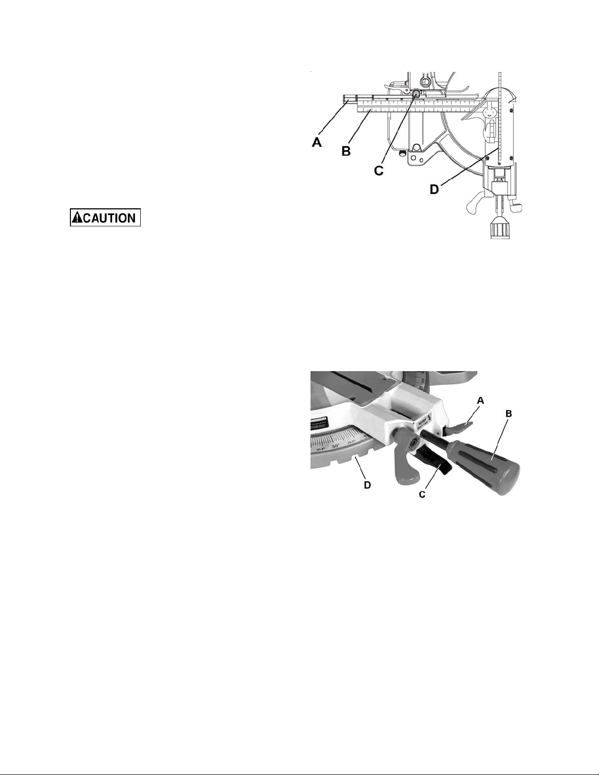
Miter Angle
The compound miter saw scale can be easily read,
showing miter angles from 0° to 45° to the left, and
0° to 45° to t he right . The mit er saw table has nine
of the most common angle settings with positive
stops at 0°, 15°, 22.5°, 31.6°, and 45°. These
positive stops position the blade at the desired
angle quickly and acc ur ately.
Figure 9
Follow the process below for quickest and most
accurate adj ustm ents.
Referring to Fi gur e 10:
1. Lift up on the quick-cam m iter table lock (B) to
unlock the table.
2. Lift up on the posit ive stop locking lever (D) and
move the turnt able with handle (C) t o align the
indicator (E) to the desired degree
measurement.
3. Lock the table into position by pressing down
on the quick-cam m iter table lock (B).
Miter Scale Indicator Adjustment
1. Move the table to the 0° positive stop.
2. Remove the table ins er t (A).
3. Loosen the screw (F) that secures the indicator (E).
4. Adjust the indicator (E) to the 0° mark and
retighten screw (F).
5. Replace the table inser t (A).
Figure 10
15
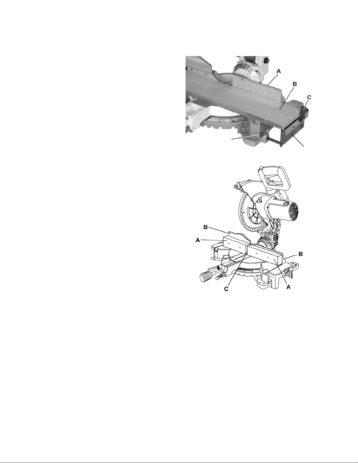
Adjusting Fence Squareness
Referring to Fi gur e 11:
1. Loosen two fence locking sc r ews (C).
Note: One lo ck in g s cre w is lo c at e d on ea ch fence.
2. Lower the cutti ng arm and lock in position.
3. Using a square (B), lay the heel of t he square
against the blade (D) and t he ruler agai nst the
fence (A).
4. Adjust the fence 90° to the blade and tighten
the two fence locking sc r ews (C).
If the saw has not been used
recently, recheck blade sq uareness to the fence
and readjust if needed.
5. After fence has been aligned, using a scrap
piece of wood, make a cut at 90º then check
squareness on the piece. Readjust if
necessary.
Positive Stop Miter Angle Adjustment
Referring to Fi gur e 12:
1. Unlock the mi ter table by lifti ng up on the quick-
cam miter table lock (A).
Figure 11
2. Raise the positive stop locking lever (C) up; at the
same tim e grasp the miter han dle (B) and rot ate
the miter table left or right to the desired angle.
3. Release the posit ive stop locking lever (C) and
set the mit er at the desired angle making sure
the lever snaps int o plac e.
Note: There are ni ne posi tive stops into which the
lever will lock.
4. After t he angle is selected, press down on the
quick-cam miter table lock (A).
Quick-cam Miter Table Lock Operation
If a miter angl e required is not one of nine posit ive
stops, the miter table can be locked at any angle
between these positive stops by using the quickcam miter table lock.
Referring to Fi gur e 12:
1. Unlock the mi ter table by lifti ng up on the quick-
cam miter table lock (A).
2. Raise the positive stop locking lever ( C) up; at
the same time gr asp the miter handle (B) and
rotate the m iter tabl e left or r ight t o the desired
angle.
Figure 12
3. Release the positive stop locking lever (C).
4. Press do wn on t he quick-cam mit er table lock
(A) until it locks the miter table in place.
Note: The quick-cam miter table lock should lock
the tabl e and prevent it f rom m oving. If adj ustment
is needed, see Quick-cam Miter Table Lock
Adjustment on following page.
16
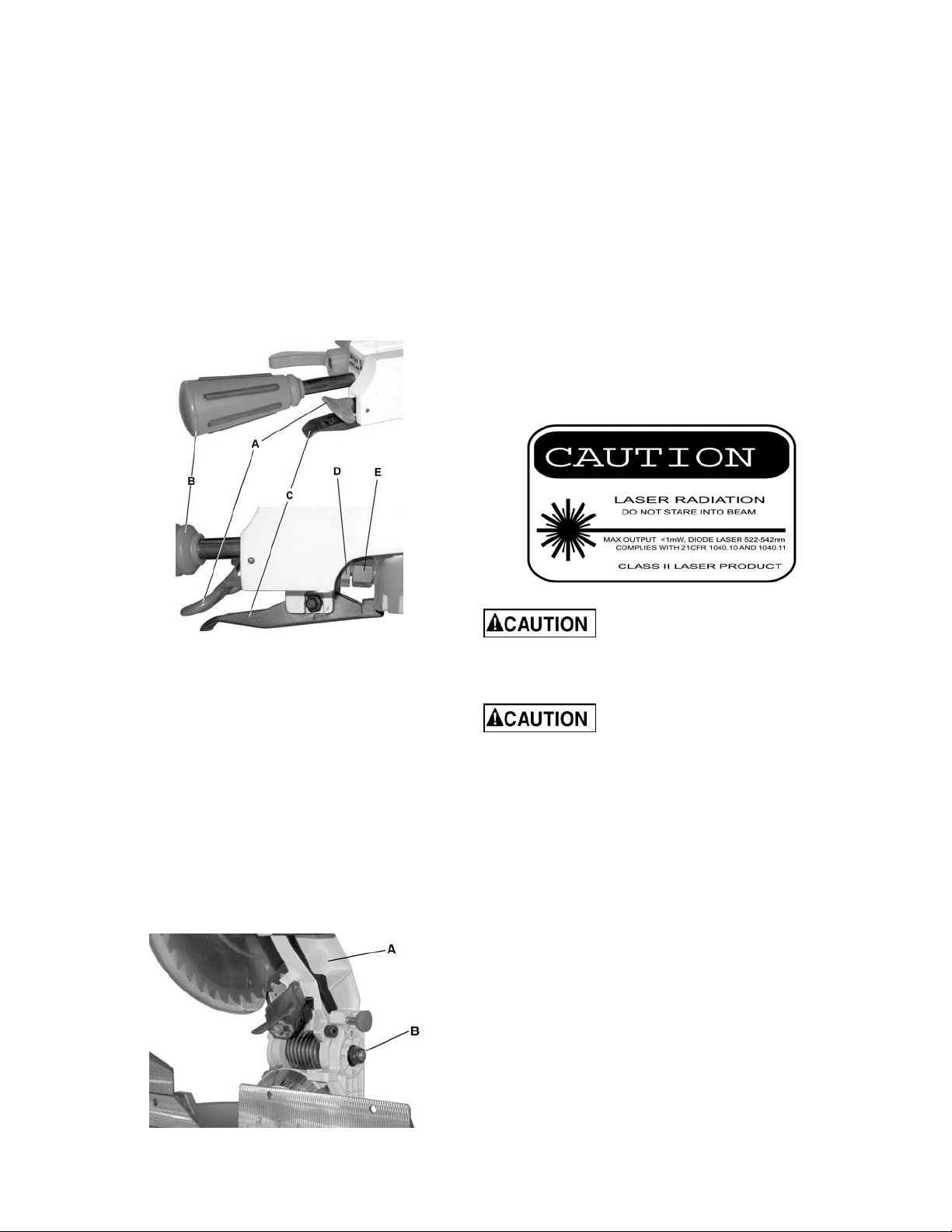
Quick-cam Miter Table Lock Adjustment
Laser Beam
Referring to Fi gur e 13:
1. Pl ace the qui ck-cam miter lock (A) in t he down
position t o loc k.
2. Loosen the lock nut (D) with a 13mm wrench,
then turn the stop nut (E) to ext end the loc king
arm against the base of the miter saw.
3. Test the qui ck-cam miter lock (C) to verify that
it locks the table securely into position.
4. Tighten the lock nut (D) to lock the miter
locking mechanism into place.
The laser is turned on with a switc h located on the
saw handle (C, Fi g. 15). W hen left on i ndefi nitely, a
sensor will turn the laser off after 20 minutes. The
switch must be reset (turned off for two seconds,
then on again) to restart.
The laser has no adjustments and should not
require adjustment. If adjustment should become
necessary, take the miter saw to an approved
service center.
• Laser radiat ion. Avoid direct eye exposure.
Always un-plug miter saw from power
source before making any adjustments.
• Laser Warning Label: Max output <1mW
DIODE LASER: 522-542nm, Complies with
21CFR 1040.10 and 1040.11.
Figure 13
Cutting Arm Pivot Adjustment
The raising and loweri ng of the cutting arm should
be free of si de-to-side play for accurate miter cuts.
It should be tight enough to prevent side-to-side
movement while still allowing the arm to move
freely up and down when cutting.
Referring to Fi gur e 14:
If the cut ting arm (A ) is too loose, tighten by turning
the cut ting arm a djusting nut (B) cl ockwise with a 19
mm wrench to tighten.
If cutt i ng arm tr avel is too ti ght, turn the cutting arm
adjusting nut counterclockwise.
Use of controls or adjustments
or performance of procedures other than those
specified in this manual may result in
hazardous radiat io n exp osure.
The use of optical instruments
with this produ ct will increase eye hazard.
• Do not attemp t to repair o r disassemble t he
laser. If unqualified persons attempt to
repair thi s laser p rodu ct, seri ous i nju ry may
result. Any repair required on this laser
product should be performed by authorized
service center personnel.
Figure 14
17
Operation
Before attempt in g an y op erat ion
with your miter saw, make sure that you have
read and thoroughly understand the warnings
contained on pages 4-5 and the Compound
Miter Saw Safety section on page 6. Failure to
comply may result in serious injury!
Starting a cut
1. Place hands at least 6-3/4 in. away from the
path of the blade.
2. Hold workpiece firmly against the fence to
prevent movement toward the blade.
3. Bri ng the saw blade down to the workpiece to
see the cutti ng path of the blade.
4. Squeeze the trigger sw itch (A, Fig. 15) to start
saw.
5. Lower blade into workpiece with a firm
downward motion.
Finishing a cut
C
1. Hold the cutting arm in the down position.
2. Release tri gger switch (A, Fig. 15) and wait for
all moving parts to stop before moving your
hands and raising t he c utti ng arm.
3. If the blade does not stop within 10 seconds,
unplug the saw and follow the instructions in
the Troubleshooting section.
Jammed Material
If material becomes jammed:
1. Release trigger switc h.
2. Wait for all moving parts to stop.
3. Unplug the mit er saw.
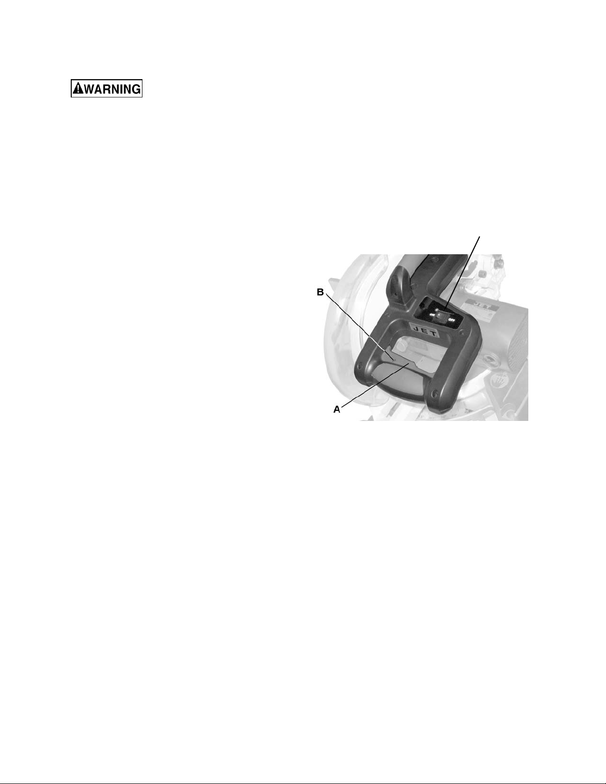
To Turn the Saw On
Depress the tri gger switc h ( A, Fig. 15).
Note: Make the On/Off switch child-proof by
inserting a padl ock through the hol e (B, Fig. 15) in
the trigger switch.
The miter saw is equipped with an autom atic blade
brake. When the trigger switch is released, the
electric blade brake will stop the blade within
approxim ately 10 seconds.
Figure 15
18

Sliding Fence
The sliding fence must be
extended to the left or right when making bevel
cuts. Failure to comply may cause serious injury!
Failure to extend the sliding fence will not allow
enough space for the blade to pass through. This
could result in serious injury. At extreme miter or
bevel angles the saw blade may also contact the
fence resul ting in damage t o equipment as well as
personal injury.
To adjust the sliding fence (refer to Figure 16):
1. Unlock the fence cam locking lever (A) (shown
locked in Figure 16) by pushing it toward the
rear of the machi ne.
2. Extend the fence (B) by sliding it out (C) to
ensure that the blade will clear the fence for
degree of the bevel cut selected. Lock the
fence cam locking lev er (A) as shown.
Note: Secure t he sliding f enc e in posi tion closest to
the saw blade when transporting the saw.
Miter Cut
Referring to Fi gur e 17:
The sliding com pound miter saw has nine positiv e
miter stop detents (A) located on the saw base.
The stops represent the f ollowing mit er cut angles:
0, 15, 22.5, 31. 6 and 45 de grees lef t and right. To
make a miter cut:
1. Unlock the mi ter table by lifti ng up on the quick-
cam miter table lock (E).
2. Raise the positive stop locking lever ( C) up, at
the same time grasp the mit er handle (D) and
rotate the m iter tabl e left or r ight t o the desired
angle.
3. Release the positive stop locking lever (C),
making sure the lev er snaps into plac e at one
of the miter stop detents (A).
Figure 16
Note: The mi ter can be set f or any angle bet ween
0° and 45° left and right. However, the lever will
only lock into place at one of the nine positive st ops
indicated above.
Once the desired miter angle is achieved:
4. Press down on the quick cam miter table
lock (E) to secure the table into position.
If the miter angle desired is not one of the nine
positive stops noted above:
5. Simply lock the table at the desired angle by
pressing down on the quick-cam miter table
lock (E).
Figure 17
19
Bevel Cut
The sliding fence must be
extended to the left when making bevel cuts.
Failure to comply may cause serious injury!
Failure to extend the sliding fence will not allow
enough space for the blade to pass through. This
could result in serious injury. At extreme miter or
bevel angles the saw blade may also contact the
fence resul ting in damage t o equipment as well as
personal injury.
Referring to Fi gur e 18:
1. Loosen the bevel loc k handle (B).
2. Tilt the cutting head to the desir ed level ranging
from 0° for a straight cut to a 45° left bevel as
displayed on the bev el s c ale (F).
3. Tighten the bevel lock handle (B) by pushing
down to lock the cutti ng head in posi tion.
Compound Cuts
Referring to Fi gur e 18:
G
Setting the bevel angle
1. Extend the fence (G) by sliding it out to the
required location (see Sliding Fence on page 19).
2. Loosen the bevel loc k handle (B).
3. Set the desired bevel angle; then lock the bevel
lock handle (B).
Setting the miter angle
4. Unlock the mi ter table by lifti ng up on the quick-
cam miter table lock (E).
5. Raise the positive stop locking lever (C) up, at the
same tim e grasp the miter handle (D) and rotate
the miter table left or right to the desired angle.
6. Release the positive stop locking lever (C).
7. Lock the mi ter table by pressing down on the
quick-cam miter table lock (E).
Cutting Bowed Material
Always unplug the saw when
removing small pieces of debris. Failure to
comply may cause seriou s injury!
Figure 18
Referring to Fi gur e 19:
1. Position a curved workpiece (A) again st th e fe nc e (B).
2. Secure the curved workpiece with a clamping
device (C).
Cutting a curv ed workpiece without t he support of
the fence and clamping device could result in
personal injury.
Figure 19
20
Repetitive Cutting
Note: Long workpieces need extension table
support.
Referring to Fi gur e 20:
Loosen the knob (E) then sli de the extension wing
(D) to desired position and tighten the knob.
The stop plate (C) is designed for use during
repetitiv e cutting. Sim ply r otate the stop plate (C) to
vertic al posi tion.
Auxiliary Wood Fence
Referring to Fi gur e 21:
When making repetitive cuts that produce cut-off
pieces of one i nch or less, i t i s possi ble f or t he saw
blade to catc h the cut-off piece and throw it out of
the saw or into the blade guard and housing,
possibly causing damage or injury. To minimize
this, construct an auxiliary wood fence (A) to be
mounted to y our saw which will provide additional
depth of cut. Mounting holes are provided on the
saw fence (B) for this purpose.
1. Construct the auxiliary wood fence (A) of a
single, straight piece of wood approximately 3/4
in. thick by 1-1/2 in. high by 22 in. long.
2. Attach the wood fenc e (A) securely to the saw
fence (B)
3. Make a full depth cut t o creat e a blade slot (C).
Check for interf erence between the wood f ence
and the lower blade guard.
E
Figure 20
Figure 21
D
4. Make adjustment if necessary.
Note: Adding a 3/ 4" thick auxiliary wood f ence will
also add cutti ng capacity (see Cutting Capacity on
page 7).
21

Cutting Base Molding
Crown Molding
Base moldings and many other moldings can be
cut on a compound miter saw. The setup of the
saw depends on molding characteristics and
application, as shown. Perform practice cuts on
scrap material to achieve best results:
1. Always make sure m oldings rest firmly against
fence and table. Use hold-down, crown mol ding
vise or C-clamps, whenever possible, and
place tape on the area bei ng clamped to avoid
marks.
2. Reduce spli ntering by taping the cut area prior
to making t he cut. Mark the cut line directly on
the tape.
3. Splintering typically happens due to an
incorrect blade applic ation and thinnes s of the
material.
Note: Always perform a dry run cut so you can
determine if the operation being attempted is
possible befor e power i s appl ied to the saw.
Your compound mi ter saw is suited for the dif ficult
task of cutting crown mol ding. To fit properly, crown
molding must be compound-mitered with extreme
accuracy. The two surfaces on a piece of crown
molding t hat fit flat against the cei ling and wall are
at angles that, when added together, equal exac tly
90°.
Most crown molding has a top rear angle (the
section that fit s flat against t he ceili ng) of 52°and a
bottom rear angl e (the section that fits flat against
the wall) of 38°.
In order to acc urately cut crown moldi ng for a 90°
inside or outside corner, lay the molding with its
broad back surfac e flat on t he saw table.
When setting the bevel and miter angles for
compound miters, remember that the settings are
interdependent; changing one changes the other,
as well.
Bevel/Miter Settings
Settings for standard crown molding lying flat on
compound mit er saw table.
Note: The chart bel ow references a com pound cut
for crown molding only when the angle between the
walls equals 90°.
Type of Cut Key
Inside corner – Left
Side
Inside corner – Right
Side
Outside corner – Left
Side
Outside corner –
Right Side
IL 33.9° 31.6° Right 1. Position top of molding against fence.
IR 33.9° 31.6° Left 1. Position bottom of molding against fence.
OL 33.9° 31.6° Left 1. Position bottom of molding against fence.
OR 33.9° 31.6° Right 1. Position top of molding against fence.
Bevel
Setting
Miter
Setting Procedure
2. Miter table set at RIGHT 31.6°.
3. LEFT side is finished piece.
2. Miter table set at LEFT 31.6°.
3. LEFT side is finished piece.
2. Miter table set at LEFT 31.6°.
3. RIGHT side is finished piece.
2. Miter table set at RIGHT 31.6°.
3. RIGHT side is finished piece
22

Crown Molding Chart
Compound miter saw miter and bev el angle settings, wall to crown molding angles
52/38º Crown Moldin g 45/45º Cr own Moldin g 52/38º Crown Moldi ng 45/45 º Crown Moldi ng
Angle
Between
Walls
100 27.32 30.43 30.68 27.03 157 7.14 9.04 8.19 8.10
101 26.91 30.08 30.24 26.73 158 6.82 8.65 7.83 7.75
102 26.50 29.73 29.80 26.42 159 6.51 8.26 7.47 7.40
103 26.09 29.38 29.36 26.12 160 6.20 7.86 7.11 7.05
104 25.69 29.02 28.92 25.81 161 5.88 7.47 6.75 6.70
105 25.29 28.67 28.48 25.50 162 5.57 7.08 6.39 6.35
106 24.89 28.31 28.05 25.19 163 5.26 6.69 6.03 6.00
107 24.49 27.96 27.62 24.87 164 4.95 6.30 5.68 5.65
108 24.10 27.59 27.19 24.56 165 4.63 5.90 5.32 5.30
109 23.71 27.23 26.77 24.24 166 4.32 5.51 4.96 4.94
110 23.32 26.87 26.34 23.93 167 4.01 5.12 4.61 4.59
111 22.93 26.51 25.92 23.61 168 3.70 4.72 4.25 4.24
112 22.55 26.15 25.50 23.29 169 3.39 4.33 3.90 3.89
113 22.17 25.78 25.08 22.97 170 3.08 3.94 3.54 3.53
114 21.79 25.42 24.66 22.66 171 2.77 3.54 3.19 3.10
115 21.42 25.05 24.25 22.33 172 2.47 3.15 2.83 2.83
116 21.04 24.68 23.84 22.01 173 2.15 2.75 2.48 2.47
117 20.67 24.31 23.43 21.68 174 1.85 2.36 2.12 2.12
118 20.30 23.94 23.02 21.36 175 1.54 1.97 1.77 1.77
119 19.93 23.57 22.61 21.03 176 1.23 1.58 1.41 1.41
120 19.57 23.20 22.21 20.70 177 0.92 1.18 1.06 1.06
121 19.20 22.83 21.80 20.38 178 0.62 0.79 0.71 0.71
122 18.84 22.46 21.40 20.05 179 0.31 0.39 0.35 0.35
123 18.48 22.09 21.00 19.72
0Miter
0Setting
67 42.93 41.08 46.89 36.13 124 18.13 21.71 20.61 19.39
68 42.39 40.79 46.35 35.89 125 17.77 21.34 20.21 19.06
69 41.85 40.50 45.81 35.64 126 17.42 20.96 19.81 18.72
70 41.32 40.20 45.28 35.40 127 17.06 20.59 19.42 18.39
71 40.79 39.90 44.75 35.15 128 16.71 20.21 19.03 18.06
72 40.28 39.61 44.22 34.89 129 16.37 19.83 18.64 17.72
73 39.76 39.30 43.70 34.64 130 16.02 19.45 18.25 17.39
74 39.25 39.00 43.18 35.38 131 15.67 19.07 17.86 17.05
75 38.74 38.69 42.66 34.12 132 15.33 18.69 17.48 16.71
76 38.24 38.39 42.15 33.86 133 14.99 18.31 17.09 16.38
77 37.74 38.08 41.64 33.60 134 14.66 17.93 16.71 16.04
78 37.24 37.76 41.13 33.33 135 14.30 17.55 16.32 15.70
79 36.75 37.45 40.62 33.07 136 13.97 17.17 15.94 15.36
80 36.27 37.13 40.12 32.80 137 13.63 16.79 15.56 15.02
81 35.79 36.81 39.62 32.53 138 13.30 16.40 15.19 14.62
82 35.31 36.49 39.13 32.25 139 12.96 16.02 14.81 14.34
83 34.83 36.17 38.63 31.98 140 12.63 15.64 14.43 14.00
84 34.36 35.85 38.14 31.70 141 12.30 15.25 14.06 13.65
85 33.90 35.52 37.66 31.42 142 11.97 14.87 13.68 13.31
86 33.43 35.19 37.17 31.34 143 11.64 14.48 13.31 12.97
87 32.97 34.86 36.69 30.86 144 11.31 14.09 12.94 12.62
88 32.52 34.53 36.21 30.57 145 10.99 13.71 12.57 12.29
89 32.07 34.20 35.74 30.29 146 10.66 13.32 12.20 11.93
90 31.62 33.86 35.26 30.00 147 10.34 12.93 11.83 11.59
91 31.17 33.53 34.79 29.71 148 10.01 12.54 11.46 11.24
92 30.73 33.19 34.33 29.42 149 9.69 12.16 11.09 10.89
93 30.30 32.86 33.86 29.13 150 9.37 11.77 10.73 10.55
94 29.86 32.51 33.40 28.83 151 9.05 11.38 10.36 10.20
95 29.43 32.17 32.94 28.54 152 8.73 10.99 10.00 9.85
96 29.00 31.82 32.48 28.24 153 8.41 10.60 9.63 9.50
97 28.58 31.48 32.02 27.94 154 8.09 10.21 9.27 9.15
98 28.16 31.13 31.58 27.64 155 7.77 9.82 8.91 8.80
99 27.74 30.78 31.13 27.34 156 7.46 9.43 8.55 8.45
0Bevel
0Setting
0Miter
0Setting
0Bevel
0Setting
Angle
Between
Walls
0Miter
0Setting
0Bevel
0Setting
0Miter
0Setting
0Bevel
0Setting
23

Maintenance
Lower Blade Guard
To avoid injury while
performing maintenance, always unplug the
power cord before working on the saw.
Failure to compl y may cause seri ou s injury!
Never use gasoline or any
highly volatile solvents to clean the miter
saw. Failure to comply may cause serious
injury!
Use only replacement parts
that are id entical to the parts list at the end
of thi s manu al and reassembl e exact ly as the
original assembly to avoid electrical shock.
Failure to compl y may cause seri ou s injury!
Replacing Carbon Brushes
Replace both carbon brushes when either has
less than 1/4 in. length of carbon rem aining, or if
the spring or wire is dam aged or bur ned.
To inspect or repl ac e br ushes:
1. Unplug the saw.
2. Rem ove the bl ack plastic cap on the side of
the motor
Remove the cap cauti ousl y , because i t is springloaded.
3. Pull out the brush and repl ac e.
4. Reverse above steps to reassemble.
Tighten the cap snugly, but do not overtighten.
Replace the brush f or the ot her side in t he same
manner descri bed above.
Note: To rei nstall the same brushes, f irst make
sure the brushes go back i n the way they came
out. This will avoid a break-in period that
reduces motor performance and increases wear.
Do not use the saw without the lower blade
guard. The l ower blade guard is attached t o the
saw for your prot ection. S hould the lower g uard
become damaged, do not use the saw until the
damaged guard has been replaced. Develop a
regular check to make sure the lower guard is
working properly . Clean the lower guard of any
dust or buildup with a damp cloth.
When cleaning the lower
guard, unplug the saw from the power
source receptacle to avoid unexpected
startup.
Do not use solvents on the
guard. They coul d m ake t he pl astic “cl oudy” and
brittle.
Saw Dust
Periodic ally, saw dust will accumulate under t he
work table and base. Thi s could cause difficult y
in the m ovement of the worktable when setti ng
up a miter cut. Frequently blow out or v acuum
up the saw dust.
If blowing saw dust, wear
proper eye protection to keep debris from
entering eyes.
Lubrication
All the motor beari ngs in this tool are lubricated
with a suffi cient amount of hi gh grade lubricant
for the life of the unit under normal operating
conditions; therefore, no further lubrication is
required.
Lubricate the following as necessary:
Chop pivot: Apply light machine oil to points
indicated i n illust r ation.
Central pivot of plastic guard: Use light
household oil (sewing machine oil ) on metal-t ometal or m etal-to-plastic guard cont act areas as
required for smooth, quiet operation. Avoid
excessiv e oil, t o whic h saw dust wil l cli ng.
24

Troubleshooting – Motor
Trouble Probable Cause Remedy
1. Motor brushes not sealed or lightly
sticking.
2. Motor brake overheated from use of
defectiv e or wrong size blade or rapid
Brake does not stop
blade within 10
seconds.
Motor does not start
Bru sh sp ark when
switch released.
ON/OFF c y cling.
3. Arbor bolt loose.
4. Brus hes cr acked , damaged, etc.
5. Other.
1. Limit switch failure
2. Brush worn.
3. Fuse blown or circuit breaker tripped
on home panel.
1. Worn brush.
2. Other.
Troubleshooting – Operation
1. Inspect/clean/replace brushe s.
2. See MAINTENANCE section.
3. Use a recommended blade. Let cool
down. See REMOVING OR INSTALLING
THE BLADE section.
4. Retighten. See REMOVING OR
INSTALLING THE BLADE section.
5. Replace brushes.
Contact yo ur Service Center.
1. Replace limit swit c h.
2. Replace brushes. See Maintenance
section.
3. Verify th ere is electrical power at the
outlet.
1. Replace brushes. See Maintenance
section.
2. Cont act your Servi ce Center.
Trouble Probable Cause Remedy
Blade hits table.
Angle of cut not
accurate. Cannot
adjust miter.
Cutting arm wobbles. 1. Loose pivot points. 1. Contact Service Center.
Cutting arm will not
fully rise, or blade
guard won’t fully
close.
Blade binds, jams,
burns wood.
Saw vibrates or
shakes.
1. Misalignment. 1. See the Setting Cutting Depth section in
Adjustments
1. Miter table unlocked.
2. Saw dust under table.
1. Pivot spring not replaced properly after
service.
2. Saw dust build-up.
1. Improper operation.
2. Dull or warped blade.
3. Improper blade size.
4. Wood is moving during cut.
1. Saw blade not round / damaged /
loose.
2. Arbor bolt loose.
1. See th e M iter Angle Adjust ment section
in Operations
2. Vacuum or blow out dust.
Important: Wear eye p rot ection.
1. Contact Service Center.
2. Clean and lubricate moving parts.
1. See Op erations section .
2. Replace or sharpen blade.
3. Repl ace with 10 in. diam eter blade.
4. U se hold dow n clam p to sec ure
workpiece to table.
1. Replace blade.
2. Tighten arbor bolt.
Laser not aligned -- 1. Contact Service Center.
Las er turns off
1. Laser turns off after 20 minutes to
prevent hea t bui ldup.
1. Reset laser switch on trigger handle (turn
off for two seconds, then on again).
25

Parts
Ordering Replacement Parts
To order parts or reac h our serv i ce depar tment, call 1-800-274-6848 M onday t hrough Fr iday (see our websi te f or
business hours, www.jettools.com). Having the Model Number and Serial Number of your machine available
when you call will allow us to serve you quickly and accuratel y .
Parts List
Note: Parts without par t numbers are for reference only and cannot be pur c hased i ndividually.
Index No. Part No . Description Size Qty
1 ............... JMS10CMS-1 ..........Lower Handle ........................................................................................ 1
2 ............... JMS10SCMS-10 ......Cord Clamp ........................................................................................... 1
3 ............... JMS10CMS-3 ..........Compres sion Spring .............................................................................. 1
4 ............... JMS1 0C MS-4 ..........Sprin g Wire .............................................................................. ............. 1
5 ............... JMS10CMS-5 ..........Handle Segment .................................................................................... 1
6 ............... JMS10SCMS-19 ......Blade Wrench ........................................................................................ 1
7 ............... JMS10CMS-7 ..........Pan Head Tappi ng S crew ...................................M4-18x16 ................... 2
8 ............... JMS10SCMS-88 ......Termina l ................................................................................................ 2
9 ............... JMS10CMS-9 ..........Pan Head Tappi ng S crew ...................................M6-1x25 ..................... 2
10 ............. JMS10SCMS-69 ......Pan Head Tapping Screw ...................................M4-18x25 ................... 4
12 ............. JMS10CM S-12.........Limit Switch ........................................................................................... 1
13 ............. JMS10CMS-13.........Cord Guard ........................................................................................... 1
14 ............. JMS10SCMS-170 ....Rocker Switch ....................................................................................... 1
15 ............. JMS10CMS-15.........Lead Wire .............................................................................................. 1
16 ............. TS-1533062 .............Pan Head Screw ................................................M5x20 ........................ 1
17 ............. JMS10CMS-17.........Upper Handle ........................................................................................ 1
18 ............. JMS10CMS-18.........Trigger................................................................................................... 1
19 ............. JMS10CMS-19.........Green Laser Controller Assembl y .......................................................... 1
20 ............. JMS10CMS-20.........Pan Head Screw with Washer ............................M6x45 ........................ 2
21 ............. JMS10CMS-21.........Motor ..................................................................................................... 1
22 ............. JMS10CMS-22.........Motor Brush Cover ................................................................................ 2
23 ............. JMS10CMS-23.........Motor Brush ........................................................................................... 2
24 ............. TS-2342161 .............Nylon Insert Lock Nut .........................................M16 ............................ 1
25 ............. TS-1541041 .............Nylon Insert Lock Nut .........................................M10 ............................ 1
26 ............. TS-155010 ...............Flat Washer ........................................................M16 ............................ 2
27 ............. TS-0680041 .............Flat Wash er ........................................................3/8 .............................. 1
28 ............. JMS10CMS-28.........Special Bolt ........................................................................................... 1
29 ............. JMS10CMS-29.........Pivot Shaft ............................................................................................. 1
30 ............. TS-2171012 .............Pan Head Screw ................................................M4x6 .......................... 2
31 ............. JMS10CMS-31.........Pin......................................................................................................... 1
32 ............. JMS10CMS-32.........Table ..................................................................................................... 1
33 ............. JMS10CMS-33.........Shaft ..................................................................................................... 1
34 ............. JMS10CMS-34.........O-Ring................................................................................................... 1
35 ............. JMS10CMS-35.........Pointer................................................................................................... 1
36 ............. JMS10SCMS-14 ......Knob ..................................................................................................... 1
37 ............. TS-2342121 .............Nylon Insert Lock Nut .........................................M12 ............................ 1
38 ............. TS-0680061 .............Flat Wash er ........................................................1/2 .............................. 1
39 ............. JMS10CMS-39.........Pointer, Right......................................................................................... 1
40 ............. JMS10CMS-40.........Disc ....................................................................................................... 1
41 ............. JMS10CMS-41.........Pan Head Tapping Screw ...................................M5-16x10 ................... 1
42 ............. TS-2360121 .............Flat Washer ........................................................M12 ............................ 1
43 ............. JMS10SCMS-104 ....Bushing ................................................................................................. 1
44 ............. TS-1502051 .............Socket Head Cap Screw .....................................M5x20 ........................ 1
45 ............. JMS10CMS-45.........Locking Rod .......................................................................................... 1
46 ............. TS-1540041 .............Hex Nut ..............................................................M6 .............................. 2
47 ............. TS-1541031 .............Nylon Insert Lock Nut .........................................M8 .............................. 1
26

Parts List
Index No. Part No . Description Size Qty
48 ............. TS-1550061 .............Flat Wash er ........................................................M8 .............................. 1
49 ............. TS-1533032 .............Pan Head Screw ................................................M5x10 ........................ 1
50 ............. JMS10CMS-50.........Pointer................................................................................................... 1
51 ............. JMS12SCMS-188 ....Handle................................................................................................... 1
52 ............. TS-1482041 .............Hex Cap Screw ..................................................M6 x20 ........................ 2
53 ............. JMS10SCMS-33 ......Flat Washer ........................................................1/4x1/2x3/32 ............... 1
54 ............. TS-2361061 .............Lock Washer ......................................................M6 .............................. 1
55 ............. TS-1503041 .............Socket Head Cap Screw .....................................M6x16 ........................ 1
56 ............. JMS10CMS-56.........Pin......................................................................................................... 1
57 ............. JMS10CMS-57.........Screw Stop ............................................................................................ 1
58 ............. J MS10SCMS-8 ........Nut ........................................................................................................ 1
59 ............. J MS10SCMS-4 1 ......E-Clip .................................................................E -6 ............................. 1
60 ............. JMS10CMS-60.........Miter Lock Handle Assembl y.................................................................. 1
61 ............. ................................Miter Lock Handle.................................................................................. 1
62 ............. ................................Link ....................................................................................................... 1
63 ............. ................................Shaft ..................................................................................................... 1
64 ............. ................................Spring Pin...........................................................Ø2.5 x8 ....................... 2
65 ............. JMS10CMS-65.........Compression Spring .............................................................................. 1
66 ............. TS-1541011 .............Nylon Insert Lock Nut .........................................M5 .............................. 1
67 ............. JMS10CMS-67.........Follower Plate........................................................................................ 1
68 ............. JMS10CMS-68.........Hex Cap Screw with Flat & Lock Washers ..........M6x16 ........................ 1
69 ............. JMS10CMS-69.........Compression Spring .............................................................................. 1
70 ............. TS-1523061 .............Socket Set Screw ...............................................M6x20 ........................ 1
71 ............. TS-1502081 .............Socket Head Cap Screw .....................................M5x35 ........................ 1
73 ............. JMS10CMS-73.........Table Insert ........................................................................................... 1
74 ............. TS-2284082 .............Pan Head Screw ................................................M4x8 .......................... 4
75 ............. JMS10CMS-75.........Bevel Arm.............................................................................................. 1
76 ............. JMS10CMS-76.........Locking Handle Assembly ...................................................................... 1
77 ............. JMS10CM S-77.........Release/Stop Lever ............................................................................... 1
78 ............. JMS10SCMS-37 ......Wave Washer .....................................................WW-8 ......................... 2
79 ............. TS-1533042 .............Pan Head Screw ................................................M5x12 ........................ 2
80 ............. TS-1541011 .............Nylon Insert Lock Nut .........................................M5 .............................. 2
81 ............. JMS10CMS-81.........Extension Rod ....................................................................................... 2
82 ............. JMS10CMS-82.........Pan Head Screw ................................................M5x6 .......................... 2
83 ............. JMS10CMS-83.........Stop Pl ate, Left ...................................................................................... 1
84 ............. JMS10CMS-84.........Extension Wing, Left .............................................................................. 1
85 ............. JMS10CMS-85.........Extension Rod ....................................................................................... 2
87 ............. JMS10CMS-87.........Fence Extension .................................................................................... 1
88 ............. JMS10CMS-88.........Fence .................................................................................................... 1
89 ............. JMS10SCMS-56 ......Socket Head Cap Screw with Washer .................M8x25 ........................ 1
90 ............. JMS10CMS-90.........Socket Head Cap Screw with Washer .................M8x30 ........................ 2
91 ............. JMS10SC MS-17 ......Center Bolt ............................................................................................ 1
92 ............. JMS10SCMS-95 ......Knob ..................................................................................................... 2
93 ............. JMS10CMS-93.........Slide Plate ............................................................................................. 3
94 ............. JMS12SCMS-118 ....Knob ..................................................................................................... 2
95 ............. JMS10CMS-95.........Locking Handle Assembly ...................................................................... 1
96 ............. ................................Cush ion ................................................................................................. 1
97 ............. ................................Lock Handle .......................................................................................... 1
98 ............. ................................Pin......................................................................Ø5 x16 ........................ 1
99 ............. ................................Lock Screw ............................................................................................ 1
100 ........... ................................Plate ...................................................................................................... 1
101 ........... ................................Flat Washer ........................................................M6 .............................. 1
102 ........... ................................Nylon Insert Lock Nut .........................................M6 .............................. 1
103 ........... JMS10CMS-103.......E xte n sion Wing, R ight ........................................................................... 1
104 ........... JMS10CMS-104.......Stop Plate, Right ................................................................................... 1
105 ........... JMS10CMS-105.......Base ...................................................................................................... 1
27

Parts List
Index No. Part No . Description Size Qty
106 ........... JMS10SCMS-54 ......Arbor Bolt .............................................................................................. 1
107 ........... JMS10CMS-107.......Torsion Spring ....................................................................................... 1
108 ........... JMS10SCMS-64 ......Truss Head Round Neck Screw ..........................M6x14 ........................ 1
109 ........... JMS10SCMS-16 ......Guard Spring ......................................................................................... 1
110 ........... TS-1541021 .............Nylon Insert Lock Nut .........................................M6 .............................. 1
111 ........... JMS10SCMS-64 ......Truss Head Round Neck Screw ..........................M6x14 ........................ 1
112 ........... JMS10CMS-112.......Guard Plate ........................................................................................... 1
114 ........... JMS10CMS-114.......Blade Guard .......................................................................................... 1
115 ........... TS-1541021 .............Nylon Insert Lock Nut .........................................M6 .............................. 1
116 ........... JMS10CMS-116.......Saw Arm ............................................................................................... 1
118 ........... JMS10SCMS-1 ........Shaft Sleeve .......................................................................................... 1
119 ........... JMS10CMS-119.......Lever ..................................................................................................... 1
120 ........... TS-1503041 .............Socket Head Cap Screw .....................................M6x16 ........................ 2
121 ........... JMS10CMS-121.......Shim ...................................................................................................... 1
122 ........... TS-1503041 .............Socket Head Cap Screw .....................................M6x16 ........................ 1
123 ........... JMS10CMS-123.......A nchor Block ......................................................................................... 1
124 ........... JMS10CMS-124.......Truss Head Screw ..............................................M6x8 .......................... 1
125 ........... JMS10SCMS-15 ......Collar .................................................................................................... 1
126 ........... TS-1534051 .............Flat Head Screw .................................................M6x16 ........................ 1
127 ........... TS-1541021 .............Nylon Insert Lock Nut .........................................M6 .............................. 1
128 ........... JMS10CMS-128.......Rubber Sleeve....................................................................................... 1
129 ........... JMS10CMS-129.......Arbor Collar ........................................................................................... 2
130 ........... TS-1550041 .............Flat Washe r ........................................................M6 .............................. 1
131 ........... JMS10CMS-131.......SHCS with Plastic Lock Washer .........................M5x35 ........................ 3
134 ........... TS-1523031 .............Socket Set Screw ...............................................M6x10 ........................ 2
136 ........... JMS10CMS-136.......Link Bracket .......................................................................................... 1
137 ........... JMS10CMS-132.......Truss Head Screw ..............................................M4x8 .......................... 3
138 ........... JMS10CMS-138.......Cable Shield .......................................................................................... 1
139 ........... JMS10SCMS-37 ......Wave Washer .....................................................WW-8 ......................... 1
141 ........... TS-1541021 .............Nylon Insert Lock Nut .........................................M6 .............................. 1
142 ........... JMS10CMS-142.......A nchor Block ......................................................................................... 1
143 ........... TS-1503031 .............Socket Head Cap Screw .....................................M6x12 ........................ 1
144 ........... JMS10CMS-144.......Clamp Hold Down Assembly.................................................................. 1
145 ........... ................................Flange Pad ............................................................................................ 1
146 ........... ................................Clamp Hold Down Arm .......................................................................... 1
147 ........... ................................Flat Washer ........................................................M10 ............................ 1
148 ........... ................................Flat Washer ........................................................3/16 ............................ 1
149 ........... ................................Pan Head Screw with Lock Washer ....................M5x10 ........................ 1
150 ........... ................................Support Post ......................................................................................... 1
151 ........... ................................Lock Knob ............................................................................................. 1
152 ........... ................................Clamp Spindle & Knob Assembly ........................................................... 1
153 ........... JMS10SCMS-90 ......Dust Bag ............................................................................................... 1
154 ........... JMS10CMS-154.......Power Cord ........................................................................................... 1
155 ........... JMS10SCMS-192 ....Saw Blade ..........................................................10”x40Tx5/8” Arbor ..... 1
156 ........... JMS10SCMS-11 ......Warning Label ....................................................................................... 1
157 ........... JMS10CMS-157.......Label: Miter Quick Lock ......................................................................... 1
158 ........... JMS10SCMS-103 ....Warning Label: Avoid Exposure ............................................................. 1
159 ........... JMS10CMS-159.......Bevel Angle Scale ................................................................................. 1
160 ........... JMS10CMS-160.......Miter Angle Scale .................................................................................. 1
161 ........... JMS10CMS-161.......ID Label ................................................................................................. 1
162 ........... JMS10CMS-162.......Label: Laser On/Off ............................................................................... 1
163 ........... JMS10CMS-163.......JET Label for Handle ............................................................................. 1
164 ........... JMS10SCMS-202 ....JET Label .............................................................................................. 1
165 ........... JMS10SCMS-198 ....Label: Laser Cauti on.............................................................................. 1
166 ........... JMS10SCMS-172 ....Label: Do Not Remove .......................................................................... 1
28

Parts List
Index No. Part No . Description Size Qty
167 ........... JMS10CMS-167.......Label: Bevel Lock .................................................................................. 1
168 ........... JMS10SCMS-93 ......Label: Rotation ...................................................................................... 1
169 ........... JMS10CMS-169.......Cross Recessed Truss Head Tapping Screw ......M3-24x8 ..................... 1
170 ........... TS-1550021 .............Flat Washe r ........................................................M4 .............................. 1
171 ........... TS-1533042 .............Cross Recessed Pan Head Screw ......................M5x12 ........................ 4
172 ........... JMS10CMS-172.......Cross Rec. Pan Head Round Neck Screw ..........M6x9 .......................... 1
173 ........... JMS10CMS-173.......Laser Assembly ..................................................................................... 1
174 ........... JMS10CMS-174.......Cross Recessed Truss Head Screw....................M4x10 ........................ 4
175 ........... JMS10CMS-175.......C over .................................................................................................... 2
176 ........... JMS10CMS-176.......Slotted Set Screw ...............................................M6x8 .......................... 4
177 ........... JMS10CMS-177.......Fla t Wash er ........................................................M5x14- T1 ................... 4
178 ........... JMS10CMS-178.......Bracing Plate ......................................................................................... 2
179 ........... JMS10CMS-179.......Laser Plunger Housing .......................................................................... 1
29

Assembly Drawing
30

Assembly Drawing (continued)
31

Assembly Drawing (continued)
32
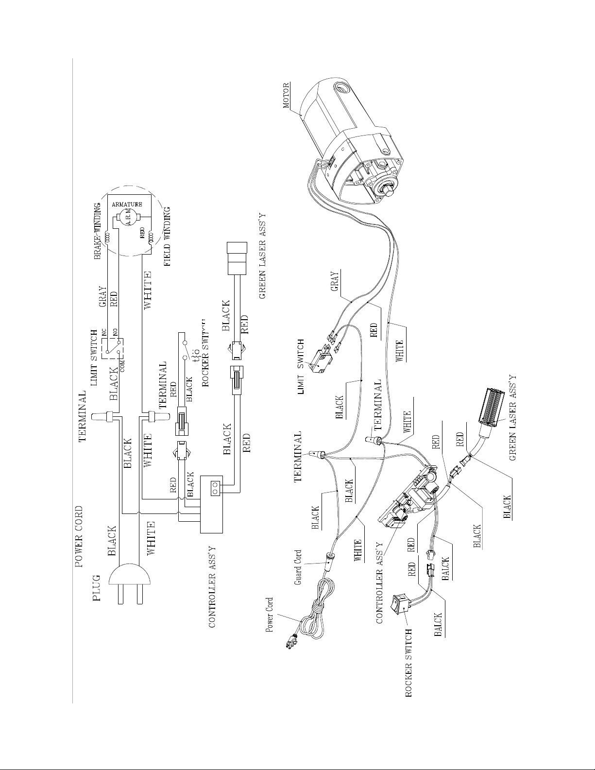
Wiring Diagram
33

This page int entionally left blank.
34

This page int entionally left blank.
35

427 New Sanford Road
LaVergne, Tennessee 37086
Phone: 800-274-6848
www.jettools.com
36
 Loading...