


Pne umatic R ivet Bust er
#550610, JC T- 261 0
#550611, JC T- 261 1
#550612, JC T- 261 2
JCT-2611 shown
Operation & Parts Manual
M-550610
Edition 1
07/2016
427 New Sanford Road
LaVergne, TN 37086
Ph.: 800-274-6848
www.jettools.com
Copyright © 2016 JET
JET

Safety warnings
General air tool warnings
1. Read and understand this entire manual
before at t em pt i ng assembl y or op er ati on.
2. Read and und erstan d all warnin gs posted on
the tool an d in th is manu al . Failur e t o comp ly
with all of thes e warnings may caus e serious
injury.
3. Replace warning labels if they become
obscur ed or r em o ved .
4. Do not use this tool for other than its intended
use. If used for other purposes, JET disclaims
any real or implied warranty and holds itself
harmless from any injury that may result from
that use.
5. Alw ays wear appr oved saf ety glass es or f ace
shield while using this tool. (Everyday
eyeglasses only have impact resistant lenses;
they are not safet y glas ses.)
6. Wear ear protectors (plugs or muffs) if the
noise exceeds safe levels.
7. Wear gloves and protective clothing if
operati on produc es sp arks or fl ying part icles.
Gloves s hould be t ight-fitti ng, withou t frayed
fingers or hangi ng threads . Keep h ands and
body away from the work in g area of tool.
8. Some dust created by power sanding, sawing,
grinding, drilling and other construction
activit ies c ont ai ns ch em ic als known t o c aus e
cancer, birth defects or other reproductive
harm. Some examples of these chemicals
are:
• Lead from lead based paint.
• Crystalline silica from bricks, cement and
other mas onry prod uc ts .
• Arsenic and chromium from chemically
treated lumber.
Your risk of exposure varies, depending on
how often you d o this type of work. To r educe
your exp osure to th ese chemic als, wor k in a
well-ventilated area and work wit h approved
safety equipme nt, su ch as face or dust masks
that are specifically designed to filter out
microscopic particles.
9. D o not operat e an air tool c ontinually at full
throttl e wit h ou t a w ork l oad on the tool.
10. The air tool must be properly lubricated before
operatin g.
11. Never start a percussion type air tool (chipper,
breaker, buster, etc.) without securing the
tooling in the retainer and placing the tip
against the work surface.
12. Do not operate air tool without its guards in
place. Do not modify the tool.
13. Do not oper ate this tool w hile tired or un der
the influence of drugs, alcohol, or any
medication.
14. Adopt a comfortable posture with proper
balance, and maintain secure footing at all
times. Non-slip footwear or anti-skid floor
strips are recomm end ed .
15. Do not wear loose clothing or jewelry. Confine
long hair.
16. Excessive air pressure and too much free
rotati on m ay dec r ease life of the tool an d may
cause a haz ar d ous sit uation.
17. Check air hoses for wear, and keep them
away fr om heat and s harp edg es. Rep air or
replace damaged air hose immediately. Do
not carry tool by the air hose.
18. Air hose may c ause tripping hazards; keep
hose away from traffic areas.
19. Do not us e this tool near flamm able objects ,
or in pot entially exp losive envir onments. Do
not use near live electrical wires.
2 JCT-2610 Series Rivet Buster

20. Do not use power tools in damp or wet
locati on, or expose t hem to r ain. K eep wor k
area well lig ht ed.
21. Do not leave a connected tool unattended.
When not in use, disconnect tool from air
source.
22. Shut off air supply and discharge any residual
pressure from tool before removing hose,
making adjustments, changing accessories,
or storing tool.
23. Make sure tool is switched off, and your finger
off the trigger, before connecting to air supply.
24. Remove ad jus tin g keys and wrenc hes befor e
turning on tool.
25. K eep visitors a safe distanc e from the work
area. Keep children away.
26. Gi ve your work undivi ded attention. Looking
around, carrying on a conversation and
“horse-play” are careless acts that can result
in serious injury.
27. D o not forc e a tool or attac hment t o do a job
for which it was n ot designed. Th e right tool
will do the job better and more safely.
28. Repetitive motions and/or exposure to
constant vibration can be harmful to hands
and arms. Take frequent breaks and relax
hands during extended operation. Change
postur e t o avoi d dis comf ort or f atig ue.
29. Compressed air can be harmful if directed
toward s ensitive areas of the body, and may
propel small particles caught in the air stream.
Exercise proper c aut i on.
30. Use only recommended accessories;
improp er accessories may be haz ardous.
31. Maint ain tools with c are. Keep air tool clean
and oiled for best and safest performance.
32. Do not use combustible gases, carbon
dioxid e, oxygen or any bottl ed gas as an air
sourc e for the tool. These can pr es ent ris k of
explosion and serious injury.
33. Do not lubricate the tool with combustible
liquids, such as kerosene, diesel or jet fuel.
34. Do not dispose of this tool with normal
household waste. Never dispose of the air tool
into fire.
Specific warni ng s for Rivet Busters
35. This rivet bus t er is desi gned and int ended f or
use by properly trained and experienced
personn el only. If you ar e not familiar with the
proper and safe operation of a pneumatic rivet
buster, do not us e until prop er training and
knowledge have b een obtained.
36. Use only correct working steel with proper
shank and dimensions for this rivet buster,
and that have a sharp cutting edge. Make sure
steel is secured in rivet buster before pressing
throttle lever.
37. Disconnect machine from air supply before
changi ng wor ki ng st eel.
38. D o not point wor king st eel towar d yours elf or
bystanders.
39. H old steel f irml y agains t work s urf ace befor e
pre s sing throttle lever.
40. Always grip rivet buster with both hands.
41. Direct tool exhaust away from yourself and
others.
42. A wor king steel may bec ome hot and caus e
burns if touched. A llow steel to c ool before
removal or adj us tm en t s .
Familiarize yourself with the following safety notices used in this manual:
fatal, injury.
possible tool damage.
This m eans that i f preca utions are not heed ed, it m ay result i n seriou s, or even
This means that if precautions are not heeded, it may result in minor injury and/or
JET 3

About this manual
This manual is provided by JET, covering the safe operation and maintenance procedures for a JET Model
JCT- 2610 series Rivet B us t er . T his man u al contai ns i ns t r uc tions on s afety pr ec au ti ons , general op er at ing
procedu res, maint enance pr ocedures and parts breakdow n. Y ou r tool has been desig n ed and construc ted
to provide consistent, long-term operation if used in accordance with the instructions set forth in this
document.
The instructions and warnings in this manual may not encompass all possible workplace environments. The
operator is expected to take appropriate precautions and exercise common sense. As with any tool
operati on, s af ety of operat or an d b yst anders shou ld be first pri or it y.
If ther e ar e questions or comments , p lease c ont act your local supp li e r or J E T . J E T can also be reac h ed at
our web site: www.jettools.com.
Record the serial number and purchase information of your tool on the cover of this manual for quick access.
Retain this manual for future reference. If the tool transfers ownership, the manual should accompany it.
Register your product online -
http://www.jettools.com/us/en/service-and-support/warranty/registration/
4 JCT-2610 Series Rivet Buster

Tool speci fic at io ns
Model nu mb er JCT-2610
Stock number 550610
Bore 1-3/16 in. (30mm)
Piston stroke 11 in. (279mm)
Impa ct rate (blows per minute) 850
Rivet capacity 1-1/4 in.
Energy per blow @90psi 80 lbf•ft
Average air consumption 44 CFM
Air inlet 1/2 in. NPT
Air hose minimum ins id e diameter 1/2 in.
Required air pressure 90 psi (6.2 bar)
Vibrati on val ue 14 m/s2 15 m/s2 15 m/s2
Noise lev el 1 95-100 dB
Overall length 25-1/2 in. (279mm)
Handle D-style, drop-forged
Retainer style Jumbo 11X
Housing material Steel
Required oil Air Tool Oil (or ISO VG32/SAE 10W equivalent)
Net weight 33 lb. (15 kg)
Shippin g w ei ght 35 lb. (15.9 kg)
1
The specifi ed valu es ar e emissi on l evels an d are not ne c essari ly to be seen as saf e oper ating le vels . As
workplace condit ions var y, this inf ormat i on is inten ded to al l ow the user t o make a bett er es tim ation of t he
hazards and risks involved only.
Specifications were current at time of publication, but because of our policy of continuous improvement, JET
reserves the right to change specifications at any time and without prior notice, without incurring obligations.
JCT-2611
550611
8 in. (203mm)
1,140
1-1/8 in.
60 lbf•ft
44 CFM
22-1/2 in. (572mm)
30 lb. (14kg)
32 lb. (13. 6 kg)
JCT-2612
550612
6 in. (153mm)
1,560
1-1/16 in.
45 lbf•ft
50 CFM
20-1/2 in. (522mm)
26 lb. (12 kg)
28 lb. (12. 7 kg)
JET 5

Setup and A ss em bly
Any missing parts or damage should be reported
immediately to your JET
damaged tool. Read this instruction manual
thoroug hly for op er ation, mai ntenanc e an d safety
instructions.
Box contents:
1 Rivet buster
1 Screw clamp
1 Operati on and p ar ts m anu al
1 Warranty card
®
distrib uto r. Do no t use a
sure upp er sl ee ve is fitt ed int o c ylind er, an d
lower sleeve and bumper are fitted into
retainer.)
5. Slide steel and retainer onto cylinder. Shank
of steel should be fully inserted into cylinder,
and retain er sl ot s h ould align wit h groove on
cylinder .
Figure 2 (chi sel not pro vided)
6. Install sprin g by feeding it into groov e until
completely installed. If needed, spray
lubricant into groove to facilitate spring
insertion. Tug sharply on the working steel to
ensure it is secure.
Figu re 1
1. Rotate exhaust deflector (Figure 1) until
exhaus t holes p oint aw ay fr om oper ator an d
bystanders.
2. Install sc rew cl amp on exhaust d eflector to
secure its position.
Operation
The rivet buster must be
properly lubricated before operation. See
“Lubrication” se ctio n.
1. Install working steel (not provided) as
follows. See Figure 2.
2. Place scr ewdriver or other tool in triangular
end of retai n er sprin g, an d pull sprin g out of
groove.
3. Slide retain er off cylind er. If needed , insert
screwdriver into slot and use as wedge to
help loosen retainer.
4. Lubricate shank of working steel with grease.
Insert st eel throug h rear of ret ainer. (M ake
6 JCT-2610 Series Rivet Buster
be ejected from the cylinder with force,
causing injury. Retainer and retainer
spring mu st be proper ly install ed befor e
using rivet buster.
7. R emove protective cap from air inl et (Figur e
1). If an in- lin e oiler is not being used, add 4
or 5 drops of air tool oil (not included) into the
air inlet.
8. Blow out air line to remove any dirt or
moisture, then connect air supply hose to
tool. Set air pressure to 90 psi.
IMPORTANT: Connecting a quick-change
coupling directly to the tool is not
recomm ended, as vibr ation may c ause the
connection to fail. Instead, add a leader hose
and install any quick-change couplings
farther down the line .
9. Hold rivet buster firmly with both hands.
Place end of tool in contact with work
surface, and press throttle lever. Do not push
too hard; allow tool to d o the w ork .
10. Release throttle lever to stop tool.
An unsecu red steel can

Important: Do NOT raise air pressure above
maximum rating for this rivet buster. If tool is
not accomplishing task at maximum air
pressure and flow, use a larger tool or
different means to achieve task.
Maintenance
Inspect rivet buster before each use. Ensure that
working steel is secured inside retainer. After use,
wipe dow n the tool with a r ag. Per iodic ally ap ply
light coat of oil to exposed metal surfaces to inhibit
rust.
Lubrication
The rivet buster should be lubricated daily (or
before eac h use) with air tool oil throu gh the air
inlet. D uring c ontinu al oper ation , it s hould b e reoiled every 1 to 2 hours. This can be done with an
in-line oiler, or manually. If done manually,
proceed as f ollows:
1. Dis c onnect air hos e fr om t ool .
2. Pl ac e 4 or 5 dr ops of air tool oil into air inlet.
NOTE: Air tool oil not provided; it is available
at most major hardware and tool stores. SAE
#10 oil or s ewing m achin e oil m ay be used
as a substitute. Do not use detergent oil.
3. Re-connect air. Run rivet buster at low
throttle without load for a few seconds to
distribu te the oil thr oug h out th e tool .
When you are f inished oper ati ng rivet bust er, t ur n
off air supply and press throttle lever to bleed
residual air. Disconnect air hose. Wipe off housing
with a dr y cloth. P lace 4 or 5 dr ops of air tool oi l
into air i nlet ; re- c onnec t air an d run t he t ool f or a
few sec onds to distribute oil. Bl eed residual air
again and dis c on n ect air hose.
Storage
Avoid storing the rivet buster in very humid
locations which promotes rusting of internal
mechan isms. Al ways oil t he tool and disconn ect
air hose before storage.
Air system requiremen t s
1. Use proper air hose size (refer to tool
specifications). The hose should be just long
enough to serve the working area. Excessive
hose len gth wil l c ause pressur e drop.
2. Make sure air compressor supplies clean,
dry air at correct CFM for the angle grinder.
3. Set air pressure to 90 psi.
Excess air pressure
and/or unclean air will shorte n the tool’s
life and may create a hazardous situation.
4. Drain water fr om air c ompr essor tank d aily,
as well as any c ondensati on from air lines.
W ater in the air li ne may enter the t ool and
cause damage.
5. Ch ange filters on the air syst em on a reg ul ar
basis.
6. Air-line pressure may be increased
accordi n gly to compens ate for ext ra-long air
hoses (usually over 25 feet). Inside diameter
of hose sh oul d b e minimum 1/2-inch.
General Air Tool
Information
If the air tool is not performing according to
specif ications , the f oll owing ar e am ong th e most
common causes. (See also “Troubleshooting”
section.)
• Contam inat ed air such as a dirty air s ystem
or water in the system.
• Using wrong size tool for the job.
• Poor maint enanc e prac tices, such as us ing
excessive air pr ess ure or air volu m e.
• Improper or no lubrication.
Rule of Thum b
If it takes more than 8 seconds to tighten or loosen
a bolt or nut with an air impact wrench, the air
wrench is too sm all or th e air compressor CFM is
not powerful enough for the job. Continued use in
either ca p acity will cause damage to the tool.
Tool Pressure
JET Air Tools oper ate on 70- to-100 ps i (pounds
per square inch) air pressure measured at the tool
when the tool is operating. Set tool to 90 psi
unless indicated otherwise. Pressure in excess of
100 psi will shorten the life of the tool.
JET 7

Air System Recommendat io ns
Equip the air compressor intake with a
replaceable air filter that can be easily cleaned.
Use safety shut-off valves so air flow can be
stopped quickly in case of a line break.
When us ing m ultipl e hoses , air hoses s hould be
larger than leader hose. Join multiple hoses
directly, rather than with quick connect fittings
which may c ause press ure dr ops and tool pow er
reduction.
Use anti-whip devices across hos e couplings to
prevent hose from whipping in the event of a hose
failure or c oup li ng dis connec t.
Always us e m oistur e tr aps at t he c om press or for
the mai n dis t r ib ut ion line. U se moisture traps an d
in-line oi lers on eac h downli ne that is to be used
for air tools. (See Figure 4). Place oiler as close to
air tool as possible f or best lubrication.
Lubrication
Use a light oil c ontai ni ng rust in hibit ors , ident if ied
as “Air Tool Oil,” or an ISO VG32 (SAE 10W )
equival ent. Many JET air tools have integral oil
reservoirs, which should be kept filled when in-line
oilers ar e not us ed.
If greasing is required, use a grease that is highly
water r esis t ant f or th e fr ont c as e c ompon en ts on
air impact wr enc h es , grin d er s and s an d ers.
Recycling
Protect the environment. Your tool contains
materials which can be recovered or recycled.
When its us eful life has expired, pleas e leav e t ool
at a specialized facility.
Recommended arrangement of air piping and air line system
8 JCT-2610 Series Rivet Buster
Figu re 3

Troubleshooting JCT-2610 series Rivet Busters
Any disass embly of the tool should be don e by qualifi ed service pers onnel. For prob lems not ad dressed
below, contact JET technical service at 800-274-6846.
Problem Possible cause Remedy
Tool will n ot st art . Air valve cl os ed or obstruc t ed. Open valv e; cl ear any obstructions.
Starts im m ed i ately as soon
as air is connected without
lever bei ng pressed.
Excess i ve or abnormal
vibration.
Loss of power; erratic
action.
Dirt or gum deposits on
components.
Throttl e l ever malfunc tion. Clean thr ottle lever m ech anism to
Piston s eiz ed d ue to improper
lubrication.
Throttl e valve malf unc t i on. Inspect and rep air t hr ot tl e val v e.
Improp er lubr ication. Lubric at e pr op erly accordi n g t o
Low air pressure or air volume. Verify compressor has proper CFM
Moistur e or obs t r uc t i on in air
hose.
Improp er siz e of air tr ans m is s i on
lines, hos es, fitti ngs , or
couplings. Or, air supply line too
long.
Dirt or gum deposits on
components.
Bumper or upper/lower sleeves
excessively worn.
Loss of impact, or loss of blows
per minute.
Throttle valve seizing. Inspect; clean or replace elements.
Flush tool wit h gu m solvent.
If problem persists, disassemble,
clean and lubricate internal parts.
ensure free movement. Replace
mechanism if needed.
Lubric at e t ool ac cording to
instructions.
instructions in th is manua l.
rating for tool.
Check compressor regulator
setting; set air pressure to 90 psi.
Check for loose connections at air
inlet, o-rings, etc.
Air supply must be clean and dry.
Clean out air h os e( s ) and remove
any kinks or bends.
Use appropriat e-si z ed air lines/
hoses. Verify proper fittings,
couplings. Use shorter supply line if
needed.
Flush tool wit h gu m solvent.
Check and cl ean air filt er on
compressor.
Clean ext er n al areas of tool. If
problem persists, disassemble,
clean and lubricate internal parts.
Replac e elem ents as need ed .
Check clearance between piston
and cylinder. Maximum clearance
should be 0.005 in. (0.13mm).
Check that piston moves freely and
is not seized.
JET 9

Problem Possible cause Remedy
Severe air l eak ag e.
(Note: Minimal es ca pe of
air is often n or m al f or air
tools.)
Excess i ve h eat develops
in tool.
Tool continues to operate
after releasing throttle
lever.
Steel tool is loose. Steel shank does not match
Leakage from air inlet. Change O-rings and check for
Leakag e from throttl e val ve area. Check for wear of thr ot t l e valve
Improp er lubr ication. Lubric at e pr op erly accordi n g t o
W orn intern al p ar ts . Inspect and replace as need ed .
Throttl e valve pin or bus h in g is
damaged.
Blockag e in valve area. Remove an y foreign matter.
retainer bushing.
Upper sleeve is worn. Replace upper sleeve.
loosen in g of air inlet nut.
elements. Replace as needed.
instructions in th is manua l.
Inspect and replace elem en ts as
needed.
Use steel with correct shank type.
Replacem e nt par t s
Service parts are listed on the following pages. To order parts or reach our service department, call 1-800274-684 8 Mond ay throu gh Frid ay, 8: 00 a.m. to 5: 00 p.m. CST. Pl ease hav e the st ock num ber and s erial
number of y our t ool availabl e w h en you call, so that we may serve yo u q uickly and acc uratel y.
Non-pr opri etar y par ts, s uc h as fast en ers, c an be f oun d at loc al h ard war e st ores , or m ay b e order ed f rom
JET.
Some par ts are shown for r ef er ence only, and m ay n ot b e avai l able individually.
10 JCT-2610 Series Rivet Buster
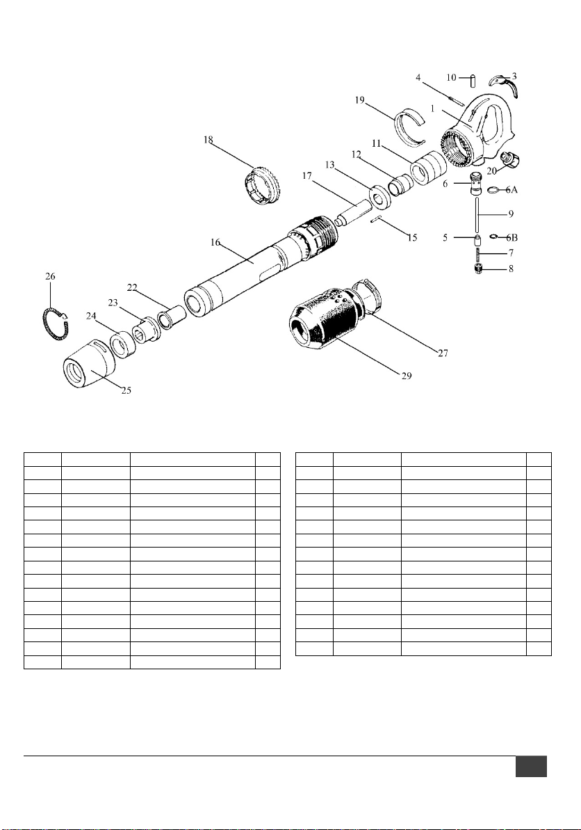
#550610, JCT-2610 Rivet Buster 11in. – exploded view
#550610, JCT-2610 Rivet Buster 11in. – parts list
Index Part No. Description Qty
1 JCT2610-01 Handle 1
JCT2610-HA Handle assembly (#1-10) 1
3 JCT2610-03 Throttle lever 1
4 JCT2610-04 Throttle lever pin 1
5 JCT2610-05 Throttle valve 1
6 JCT2610-06 Throttle valve bushing 1
6A JCT 26 1 0- 0 6A Throttl e bushin g O -r i ng 1
6B JCT2610-06B Throttle valve O-ring 1
7 JCT2610-07 Throttle valve spring 1
8 JCT2610-08 Throttle valve plug 1
9 JCT2610-09 Throttle valve pin 1
10 JCT2610-10 Valve pin bushing 1
JCT2610-VA Valve assembly (#11-15) 1
11 JCT2610-11 Valve case 1
12 JCT2610-12 Valve 1
Index Part No. Description Qty
13 JCT2610-13 Va lve cover front
15 JCT2610-15 Valve dowel pin 1
16 JCT2610-16 Cylinder 6in. 1
17 JCT2610-17 Piston 1
18 JCT2610-18 Clutch ring 1
19 JCT2610-19 Clutch band 1
20 JCT2610-20 Air inlet bushing1/2in.NPT 1
22 JCT2610-22 Upper sleeve 1
23 JCT2610-23 Lower sleeve 1
24 JCT2610-24 Urethane bumper 1
25 JCT2610-25 Retainer 1
26 JCT2610-26 Retainer spring 1
27 JCT2610-27 Screw clamp 1
29 JCT2610-29 Exhaust deflector 1
1
JET 11

#550611, JCT-2611 Rivet Buster 8in. – exploded view
#550611, JCT-2611 Rivet Buster 8in. – parts list
Index Part No. Description Qty
1 JCT2610-01 Handle 1
JCT2610-HA Handle assembly (#1-10) 1
3 JCT2610-03 Throttle lever 1
4 JCT2610-04 Throttle lever pin 1
5 JCT2610-05 Throttle valve 1
6 JCT2610-06 Throttle valve bushing 1
6A JCT 26 1 0- 0 6A Throttl e bushin g O -r i ng 1
6B JCT2610-06B Throttle valve O-ring 1
7 JCT2610-07 Throttle valve spring 1
8 JCT2610-08 Throttle valve plug 1
9 JCT2610-09 Throttle valve pin 1
10 JCT2610-10 Valve pin bushing 1
JCT2610-VA Valve assembly (#11-15) 1
11 JCT2610-11 Valve case 1
12 JCT2610-12 Valve 1
Index Part No. Description Qty
13 JCT2610-13 Va lve cover front
15 JCT2610-15 Valve dowel pin 1
16 JCT2611-16 Cylinder 8in. 1
17 JCT2611-17 Piston 1
18 JCT2610-18 Clutch ring 1
19 JCT2610-19 Clutch band 1
20 JCT2610-20 Air inlet bushing1/2in.NPT 1
22 JCT2610-22 Upper sleeve 1
23 JCT2610-23 Lower sleeve 1
24 JCT2610-24 Urethane bumper 1
25 JCT2610-25 Retainer 1
26 JCT2610-26 Retainer spring 1
27 JCT2610-27 Screw clamp 1
29 JCT2610-29 Exhaust deflector 1
1
12 JCT-2610 Series Rivet Buster

#550612, JCT-2612 Rivet Buster 6in. – exploded view
#550612, JCT-2612 Rivet Buster 6in. – parts list
Index Part No. Description Qty
1 JCT2610-01 Handle 1
JCT2610-HA Handle assembly (#1-10) 1
3 JCT2610-03 Throttle lever 1
4 JCT2610-04 Throttle lever pin 1
5 JCT2610-05 Throttle valve 1
6 JCT2610-06 Throttle valve bushing 1
6A JCT 26 1 0- 0 6A Throttl e bushin g O -r i ng 1
6B JCT2610-06B Throttle valve O-ring 1
7 JCT2610-07 Throttle valve spring 1
8 JCT2610-08 Throttle valve plug 1
9 JCT2610-09 Throttle valve pin 1
10 JCT2610-10 Valve pin bushing 1
JCT2610-VA Valve assembly (#11-15) 1
11 JCT2610-11 Valve case 1
12 JCT2610-12 Valve 1
Index Part No. Description Qty
13 JCT2610-13 Va lve cover front
15 JCT2610-15 Valve dowel pin 1
16 JCT2612-16 Cylinder 11 in. 1
17 JCT2611-17 Piston 1
18 JCT2610-18 Clutch ring 1
19 JCT2610-19 Clutch band 1
20 JCT2610-20 Air inlet bushing 1/2inNPT 1
22 JCT2610-22 Upper sleeve 1
23 JCT2610-23 Lower sleeve 1
24 JCT2610-24 Urethane bumper 1
25 JCT2610-25 Retainer 1
26 JCT2610-26 Retainer spring 1
27 JCT2610-27 Screw clamp 1
29 JCT2610-29 Exhaust deflector 1
1
JET 13

Warranty and Service
–
JET warrants every product it sells against manufacturers’ defects. If one of our tools needs service or repair, please contact
Technical Service by calling 1-800-274-6846, 8AM to 5PM CST, Monday through Friday.
Warranty Period
The general warranty lasts for the time period specified in the literature included with your product or on the official JET branded
website.
• JET products carry a limited warranty which varies in duration based upon the product. (See chart below)
• Ac c essories carry a limited warranty of one year from the date of receipt.
• C ons umable items are defined as expendable parts or accessories expected to become inoperable within a
reasonable amount of use and are covered by a 90 day limited warranty against manufacturer’s defects.
Who is Covered
This warranty covers only the initial purchaser of the product from the date of delivery.
What is Covered
This warranty covers any defects in workmanship or materials subject to the limitations stated below. This warranty does not cover
failures due directly or indirectly to misuse, abuse, negligence or accidents, normal wear-and-tear, improper repair, alterations or
lack of maintenance. JET woodworking machinery is designed to be used with Wood. Use of these machines in the processing of
metal, plastics, or other materials outside recommended guidelines, may void the warranty. The exceptions are acrylics and other
natural items that are made specifically for wood turning.
Warranty Limitations
Woodworking products with a Five Year Warranty that are used for commercial or industrial purposes default to a Two Year
Warranty. Please contact Technical Service at 1-800-274-6846 for further clarification.
How to Get Technical Support
Please contact Technical Service by calling 1-800-274-6846. Please note that you will be asked to provide proof of initial
purchase when calling. If a product requires further inspection, the Technical Service representative will explain and assist with
any additional action needed. JET has Authorized Service Centers located throughout the United States. For the name of an
Authorized Service Center in your area call 1-800-274-6846 or use the Service Center Locator on the JET website.
More Information
JET is constantly adding new products. For complete, up-to-date product information, check with your local distributor or visit the
JET website.
How State Law Applies
This warranty gives you specific legal rights, subject to applicable state law.
Limitat ions on This Wa rranty
JET LIMITS ALL IMPLIED WARRANTIES TO THE PERIOD OF THE LIMITED WARRANTY FOR EACH PRODUCT. EXCEPT AS
STATED HEREIN, ANY IMPLIED WARRANTIES OF MERCHANTABILITY AND FITNESS FOR A PARTICULAR PURPOSE ARE
EXCLUDED. SOME STATES DO NOT ALLOW LIMITATIONS ON HOW LONG AN IMPLIED WARRANTY LASTS, SO THE
ABOVE LIMITATION MAY NOT APPLY TO YOU.
JET SHALL IN NO EVEN T B E L IABLE F O R DEATH, INJURIES TO PERSONS OR PROPERTY, O R FOR INC IDENTAL,
CONTINGENT, SPECIAL, OR CONSEQUENTIAL DAMAGES ARISING FROM THE USE OF OUR PRODUCTS. SOME STATES
DO NOT ALLOW THE EXCLUSION OR LIMITATION OF INCIDENTAL OR CONSEQUENTIAL DAMAGES, SO THE ABOVE
LIMITATION OR EXCLUSION MAY NOT APPLY TO YOU.
JET sells through distributors only. The specifications listed in JET printed materials and on official JET website are given as
general information and are not binding. JET reserves the right to effect at any time, without prior notice, those alterations to parts,
fittings, and accessory equipment which they may deem necessary for any reason whatsoever. JET
sold in Canada by JPW I ndustr ies, Inc.
Product Listing with Warranty Period
NOTE: JET is a division of JPW Industries, Inc. References in this document to JET also apply to JPW Industries, Inc., or any of its
successors in interest to the JET brand.
Parts; Consumable items
90 Days
1 Year – Motors; Machin e A ccessorie s
2 Year – Metalworking Machinery; Electric Hoists, Electric Hoist Accessories; Woodworking Machinery used for industrial
or commercial purposes
5 Year – Woodworking Machinery
Limited Lifetime – JET Parallel clamps; VOLT Series Electric Hoists; Manual Hoists; Manual Hoist Accessori e s;
Shop Tools; Warehouse & Dock products; Hand Tools; Air Tools
®
branded products are not
14 JCT-2610 Series Rivet Buster

This page intentionally left blank.
JET 15

16 JCT-2610 Series Rivet Buster
427 New Sanford Road
LaVergne, Tennessee 37086
Phone: 800-274-6848
www.jettools.com
 Loading...