


This .pdf document is bookmarked
Operating Instructions and Parts Manual
2 x 72-inch Square Wheel Belt Grinder
Model J-4103
JET
427 New Sanford Road
LaVergne, Tennessee 37086 Part No. M-577000
Ph.: 800-274-6848 Revision E 08/2018
www.jettools.com Copyright © 2018 JET

1.0 IMPORTANT SAFETY
INSTRUCTIONS
- Misuse of this machine can cause serious injury.
- For safety, machine must be set up, used and
serviced properly.
- Read, understand and follow instructions in the
operator’s manual and all labels affixed to the
machine.
When setting up machine:
- Always avoid using machine in damp or poorly
lighted work areas.
- Always be sure machine is securely anchored to
the floor.
- Always keep machine guards in place.
- Always put start switch in OFF position before
plugging in machine.
When using machine:
- Never operate with machine guards missing.
- Always wear safety glasses with side shields (See
ANSI Z87.1)
- Never wear loose clothing or jewelry.
- Never overreach ⎯ you may slip and fall into the
machine.
- Never leave machine running while you are away
from it.
- Always shut off the machine when not in use.
When servicing machine:
- Always unplug machine from electrical power while
servicing.
- Always follow instructions in operators and parts
manual when changing accessory tools or parts.
- Never modify the machine without consulting JET.
1.1 Machinery general safety
warnings
1. Always wear protective eye wear when
operating machinery. Eye wear shall be impact
resistant, protective safety glasses with side
shields which comply with ANSI Z87.1
specifications. Use of eye wear which does not
comply with ANSI Z87.1 specifications could
result in severe injury from the breakage of the
eye protection.
2. Wear proper apparel. No loose clothing or
jewelry which can get caught in moving parts.
Contain long hair. Rubber soled, nonslip
footwear is recommended for best footing.
3. Do not overreach. Failure to maintain a proper
working position can cause you to fall into the
machine or cause your clothing to get caught —
pulling you into the machine.
4. Keep guards in place and in proper working
order. Do not operate the machine with the
guards removed.
5. Avoid dangerous working environments. Do not
use stationary machine tools in wet or damp
locations. Keep work areas clean and well lit.
6. Avoid accidental starts by being sure that the
start switch is in the “OFF” position before
plugging in the machine.
7. Never leave the machine running while
unattended. The machine shall be shut off
whenever it is not being used.
8. Disconnect the electrical power before
servicing, whenever changing accessories or
when general maintenance is done on the
machine.
9. Maintain all machine tools with care. Follow all
maintenance instructions for lubricating and the
changing of accessories. No attempt shall be
made to modify or have makeshift repairs done
to the machine. This not only voids the warranty
but also renders the machine unsafe.
10. If there is any risk of tipping or sliding, the
machinery must be anchored to the floor.
11. Secure your work. Use clamps or a vise to hold
your work, when practical. It is safer than using
your hands and it frees both hands to operate
the machine.
12. Never brush chips away while the machine is in
operation.
13. Keep work area clean. Cluttered areas invite
accidents.
14. Remove adjusting keys and wrenches before
turning the machine on.
15. Use the right tool. Don’t force a tool or
attachment to do a job for which it was not
designed.
16. Use only recommended accessories and follow
manufacturer’s instructions pertaining to them.
17. Keep hands in sight and clear of all moving
parts and cutting surfaces.
18. All visitors should be kept at a safe distance
from the work area. Make your workshop
completely safe by using padlocks, master
switches, or by removing starter keys.
19. Know the tool you are using; its application,
limitations, and potential hazards.
20. This machine must be grounded in accordance
with the National Electrical Code and local
codes and ordinances. The work should be
done by a qualified electrician. The machine
should be grounded to protect the user from
electrical shock.

1.2 Safety requirements for abrasive
grinding machines
Abrasive grinding can be hazardous to operators
and bystanders. Grinding sparks, chips and dust
particles thrown off by the grinding disc or belt can
cause serious injury by contact or inhalation. To
avoid such injuries you must comply with the
following safety requirements:
1. Always wear protective eyewear when
operating machinery. Eye wear shall be impact
resistant, protective safety glasses with side
shields which comply with ANSI Z87.1. Use of
eye wear which does not comply with ANSI
Z87.1 specifications could result in severe injury
from breakage of eye protection. See Figure A,
below.
2. Wear leather safety gloves, arm guards, leather
aprons and safety shoes.
3. A dust collection system is recommended,
Operator shall also wear a dust mask at all
times. See Figure B, below.
4. Additional precautions may be necessary for
grinding materials which are flammable or have
other hazardous properties. You should always
consult the manufacturer of such materials for
instructions on grinding and handling.
5. Do not force or jamb the workpiece into the
grinding disc/belt.
6. Before grinding, always allow the motor to come
up to operating speed, then check the grinding
disc for wobble, runout, or any unbalanced
condition. If the disc is not operating accurately
and smoothly, immediately stop the motor and
make repairs before attempting any grinding
operations.
7. Abrasives must be stored in a controlled
environment area. Relative humidity should be
35% to 50% and the temperature should be
between 60 and 80 degrees Fahrenheit.
Failure to do so could cause premature
abrasive failure.
8. Examine the face of the grinding disc/belt
carefully. Excessive grinding which wears down
to the backing material can tear the abrasive.
Never use an abrasive which shows backing,
nicks or cuts on the surface or edge or damage
due to creasing or poor handling.
9. When installing a new disc, be certain the disc
is accurately centered on the drive wheel.
Failure to do so could cause a serious
unbalanced condition.
10. Always present the workpiece to the wheel
while resting the workpiece firmly on the table.
Failure to do so could result in damage to the
workpiece or throwing of the workpiece off the
wheel.
11. Safety shoes which comply with ANSI Z41.1
shall be worn. See Figure C.
12. Personal hearing protection such as ear plugs
or ear muffs shall be used to protect against the
effect of noise exposure. See Figure D.
WARNING: This product can expose you to
chemicals including methyl isobutyl ketone
which is known to the State of California to cause
cancer and birth defects or other reproductive
harm. For more information go to http://www.
p65warnings.ca.gov.
WARNING: Some dust, fumes and gases
created by power sanding, sawing, grinding,
drilling, welding and other construction activities
contain chemicals known to the State of
California to cause cancer and birth defects or
other reproductive harm. Some examples of
these chemicals are:
• lead from lead based paint
• crystalline silica from bricks, cement and
other masonry products
• arsenic and chromium from chemically
treated lumber
Your risk of exposure varies, depending on how
often you do this type of work. To reduce your
exposure to these chemicals, work in a wellventilated area and work with approved safety
equipment, such as dust masks that are
specifically designed to filter out microscopic
particles. For more information go to
http://www.p65warnings.ca.gov/ and http://www.
p65warnings.ca.gov/wood.
3

Familiarize yourself with the following safety notices used in this manual:
This means that if precautions are not heeded, it may result in minor injury and/or possible
machine damage.
This means that if precautions are not heeded, it may result in serious, or possibly even fatal,
injury.
1.3 Switch lockout
To safeguard your machine from unauthorized operation and accidental starting by young children, the use of a
padlock (not included) is highly recommended. See Figure 1-1. Place the key in a location that is inaccessible to
children and others not qualified to use the tool.
Figure 1-1
4

2.0 Table of contents
Section Page
1.0 IMPORTANT SAFETY INSTRUCTIONS ....................................................................................................... 2
1.1 Machinery general safety warnings ............................................................................................................ 2
1.2 Safety requirements for abrasive grinding machines ................................................................................. 3
1.3 Switch lockout ............................................................................................................................................ 4
2.0 Table of contents ............................................................................................................................................ 5
3.0 About this manual .......................................................................................................................................... 5
4.0 General Specifications ................................................................................................................................... 6
5.0 Setup and assembly ....................................................................................................................................... 7
5.1 Contents of carton ...................................................................................................................................... 7
5.2 Installing work rest ...................................................................................................................................... 7
6.0 Electrical connections .................................................................................................................................... 7
6.1 GROUNDING INSTRUCTIONS ................................................................................................................. 7
6.2 Voltage conversion ..................................................................................................................................... 8
6.3 Extension cords .......................................................................................................................................... 8
7.0 Adjustments ................................................................................................................................................... 8
7.1 Platen or Wheel installation ........................................................................................................................ 8
7.2 Platen wheel adjustment ............................................................................................................................ 9
7.3 Grinding belt replacement .......................................................................................................................... 9
7.4 Belt tracking ................................................................................................................................................ 9
8.0 Operating controls ........................................................................................................................................ 10
8.1 Thermal overload ..................................................................................................................................... 10
8.2 Typical uses for the Square Wheel Belt Grinder ...................................................................................... 10
9.0 User-maintenance ........................................................................................................................................ 11
9.1 Cleaning ................................................................................................................................................... 11
9.2 Lubrication ................................................................................................................................................ 11
9.3 Contact wheel replacement ...................................................................................................................... 11
9.4 Additional servicing .................................................................................................................................. 11
10.0 Troubleshooting J-4103 Square Wheel Belt Grinder ................................................................................. 12
11.0 Replacement Parts ..................................................................................................................................... 13
11.1 J-4013 Square Wheel Belt Grinder – Exploded View ............................................................................. 13
11.2 J-4013 Square Wheel Belt Grinder – Parts List ..................................................................................... 14
12.0 Electrical Connections for J-4103 Belt Grinder .......................................................................................... 16
13.0 Warranty and Service ................................................................................................................................. 17
3.0 About this manual
This manual is provided by JET, covering the safe operation and maintenance procedures for a JET Model J4103 Square Wheel Belt Grinder. This manual contains instructions on installation, safety precautions, general
operating procedures, maintenance instructions and parts breakdown. Your machine has been designed and
constructed to provide consistent, long-term operation if used in accordance with the instructions set forth in this
document.
If there are questions or comments, please contact your local supplier or JET. JET c an also be reached at our
web site: www.jettools.com.
Retain this manual for future reference. If the machine transfers ownership, the manual should accompany it.
Read and understand the entire contents of this manual before attempting assembly or
operation! Failure to comply may cause serious injury!
Register your product using the mail-in card provided, or register online:
http://www.jettools.com/us/en/service-and-support/product-registration/
5

4.0 General Specifications
The JET J-4103 Square Wheel Belt Grinder is designed for grinding, deburring, chamfering, and internal/external
grinding of small and large parts. The Grinder can be used to polish or buff finished parts and grind small internal
radii using available accessories. Accessory changeover is quick and easy. Belt tension and tracking are easily
adjustable.
Table 1
Model number
Stock number 577000
Motor and Electricals
Motor type Totally enclosed, fan cooled, induction
Horsepower 1 HP
Motor phase Single
Motor voltage 115/230 V (prewired 115V)
Cycle 60 Hz
Listed FLA (full load amps) 13/6.5 A
Motor speed 1750 RPM
Power transfer Direct drive
On/off switch Toggle, with lock-out holes
Power cord and plug SJT 16AWG 300V, 8 ft., with 15A plug
Recommended circuit size 1 15 A
Capacities and dimensions
Belt included, LxW 50 grit; 72 x 2 in. (1829 x 50.8 mm)
Contact wheels included, Dia. x W 1-1/2 x 2 (38 x 50.8 mm) smooth
3 x 2 (76.2 x 50.8 mm) smooth
8 x 2 (203.2 x 50.8 mm) serrated
Overall dimensions LxWxH (approximate) 17 x 31 x 17 in. (43.2 x 78.8 x 43.2 cm)
Shipping carton LxWxH (approx.) 30-3/4 x 17-1/2 x 18 (78 x 44.5 x 45.7 cm)
Main materials
Frame Steel
Contact wheel, 8-inch Rubber, 90 Durometer
Contact wheel, 3 x 2-inch Rubber, 70 Durometer
Contact wheel, 1.5 x 2-inch Rubber, 70 Durometer
Idler wheel Rubber
Drive wheel Steel
Platen Steel
Head casting Cast iron
Weights
Net weight (approx.) 163 lb. (74 kg)
Shipping weight (approx.) 168 lb. (76.2 kg)
1
subject to local/national electrical codes.
J-4103
L = length, W = width, H = height, Dia. = diameter
The specifications in this manual were current at time of publication, but because of our policy of continuous
improvement, JET reserves the right to change specifications at any time and without prior notice, without incurring
obligations.
6
Read and understand all
assembly instructions before attempting
assembly. Failure to comply may cause
serious injury.
fuse. If connected to a circuit protected by fuses, use
time-delay fuse marked “D”. Local codes take
precedence over recommendations.
6.1 GROUNDING INSTRUCTIONS
5.0 Setup and assembly
5.1 Contents of carton
1 Grinder
1 Platen assembly (installed)
1 Serrated contact wheel 8”x2”
1 Work rest
1 Socket head cap screw
1 Hex key (Allen wrench) 5/16”
1 Grinding belt 50G
1 Operating Instructions and Parts Manual
1 Product registration card
5.2 Installing work rest
The work rest mounts to left side of head c asting.
Attach work rest with provided socket head cap
screw.
The slot in the work rest has a lip against which the
cap screw is tightened. Place the hole at end of slot
over the cap screw. Then slide work rest inward until
work rest is in position in front of contact wheel.
Tighten cap screw.
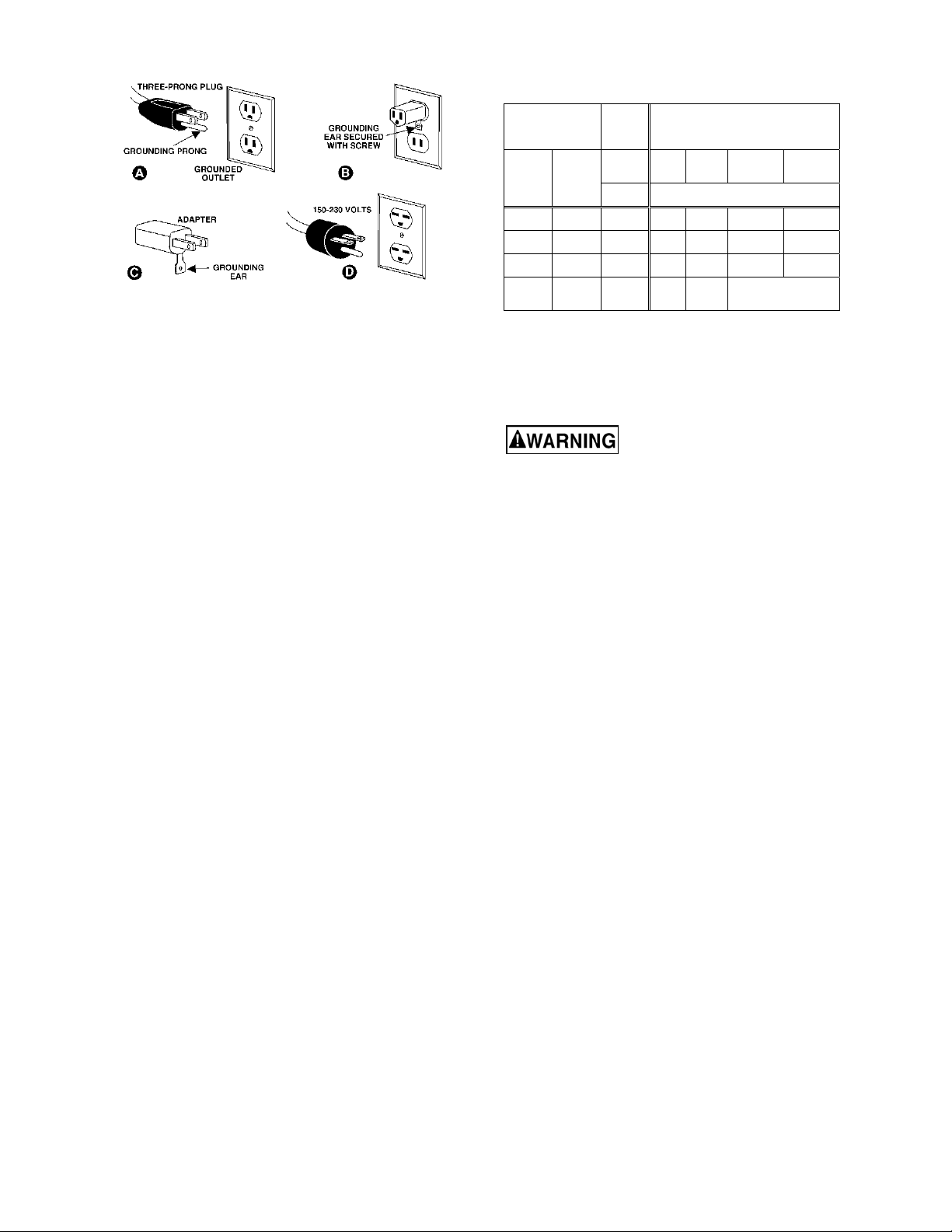
1. All Grounded, Cord-connected Tools:
This machine must be grounded. In the event of a
malfunction or breakdown, grounding provides a
path of least resistance for electric current to reduce
the risk of electric shock. This tool is equipped with
an electric cord having an equipment-grounding
conductor and a grounding plug. The plug must be
plugged into a matching outlet that is properly
installed and grounded in accordance with all local
codes and ordinances.
Do not modify the plug provided - if it will not fit the
outlet, have the proper outlet installed by a qualified
electrician.
Improper connection of the equipment-grounding
conductor can result in a risk of electric shock. The
conductor with insulation having an outer surface
that is green with or without yellow stripes is the
equipment-grounding conductor. If repair or
replacement of the electric cord or plug is
necessary, do not connect the equipment-grounding
conductor to a live terminal.
Before connecting to power source, be sure the
switch is in off position.
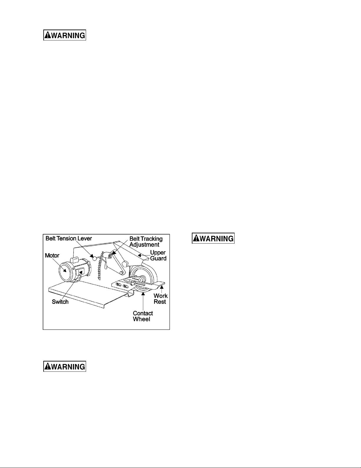
Figure 5-1: Square Wheel Grinder features
6.0 Electrical connections
Electrical connections must be
made by a qualified electrician in compliance
with all relevant codes. This machine must be
properly grounded to help prevent electrical
shock and possible fatal injury.
The J-4103 Square Wheel Grinder is pre-wired for
115V power. It may be converted to 230V power;
see sect. 6.2.
It is recommended that the grinder be connected to
a dedicated 15-amp circuit with circuit breaker or
Check with a qualified
electrician or service personnel if the grounding
instructions are not completely understood, or if
in doubt as to whether the tool is properly
grounded. Failure to comply may cause ser ious
or fatal injury.
Use only 3-wire extension cords that have 3-prong
grounding plugs and 3-pole receptacles that accept
the tool's plug.
Repair or replace damaged or worn cord
immediately.
2. Grounded, cord-connected tools intended for use
on a supply circuit having a nominal rating less than
150 volts:
This tool is intended for use on a circuit that has an
outlet that looks like the one illustrated in A, Figure
13. An adapter, shown in B and C, may be used to
connect this plug to a 2-pole receptacle as shown in
B if a properly grounded outlet is not available. The
temporary adapter should be used only until a
properly grounded. The green-colored rigid ear, lug,
and the like, extending from the adapter must be
connected to a permanent ground such as a
properly grounded outlet box.
In Canada, the use of a temporary adaptor is not
permitted by the Canadian Electrical Code, C22.1.
7
Recommended Gauges (AWG) of Extension Cords
Figure 6-1
3. Grounded, cord-connected tools intended for use
on a supply circuit having a nominal rating between
150 - 250 volts, inclusive:
This tool is intended for use on a circuit that has an
outlet that looks like the one illustrated in D, Figure
6-1. The tool is intended to be used with a grounding
plug that looks like the plug illustrated in D. Make
sure the tool is connected to an outlet having the
same configuration as the plug. No adapter is
available or should be used with this tool. If the tool
must be reconnected for use on a different type of
electric circuit, the reconnection should be made by
qualified service personnel; and after reconnection,
the tool should comply with all local codes and
ordinances.
6.2 Voltage conversion
To convert the grinder to 230-volt, single-phase
operation:
1. Switch the motor lead wires inside the motor
junction box, according to diagram found inside
junction box cover. A similar diagram is at the
back of this manual.
2. The supplied 115V plug must be replaced with
a UL/CSA listed plug suitable for 230V
operation.
6.3 Extension cords
The use of extension cords is discouraged; try to
position your machine within reach of the power
supply. If an extension cord becomes necessary,
make sure the cord rating is suitable for the
amperage listed on the machine’s motor plate. An
undersized cord will cause a drop in line voltage
resulting in loss of power and overheating.
Use the chart in Table 2 as a general guide in
choosing the correct size cord. If in doubt, use the
next heavier gauge. The smaller the gauge number,
the heavier the cord.
Ampere
Rating
More
Than
0 6 18 16 16 14
6 10 18 16 14 12
10 12 16 16 14 12
12 16 14 12
Not
More
Than
Volts
120
240
AWG
Total length of
cord in feet
25
50
50
100
Table 2
100
200
Not
Recommended
150
300
7.0 Adjustments
7.1 Platen or Wheel installation
Move switch to OFF to avoid
personal injury.
Refer to Figures 5-1 and 7-1.
To install either the platen or the 8-inch serrated
wheel:
1. Lower tension lever to release belt tension.
2. Loosen upper guard knob and swing guard
back for clearance.
3. Loosen clamping screw on head casting.
4. Install pivot shaft of platen (or shaft of wheel) all
the way into head casting.
5. Position platen as desired:
• For grinding flat or angular workpieces,
position platen with platen surface facing
outward.
• For grinding of cylindrical workpieces,
position platen with “yoke” side facing
outward.
6. Set platen at desired angle and tighten
clamping screw.
7. Install and track the abrasive belt (see sect. 7.3
and 7.4).
8. Raise tension lever to set belt tension.
9. Bring upper guard down into position and adjust
so that it will not contact abrasive belt. Tighten
upper guard knob.
8

7.2 Platen wheel adjustment
The platen wheels have eccentric shafts, which
allow adjustment of the wheels tangent to the
surface of the platen.
Turn screw (A, Figure 7-1) to adjust.
Figure 7-1: installing platen assembly
7.3 Grinding belt replacement
Do not operate machine with
side panel open.
1. Refer to Figure 7-2. Lower belt tension lever to
release tension on belt.
2. Loosen knob and raise upper guard. Open side
panel by turning its knob.
3. If required, loosen work rest to provide
clearance for belt removal.
4. Remove belt from drive wheel, idler wheel, and
contact wheel. Install replacement belt centered
over drive wheel, idler wheel, and contact
wheel. Make sure direction arrows on belt
match machine operation.
5. Raise belt tension lever to tighten belt agains t
the wheels. Tighten belt until it is just taut. Do
not over-tension the abrasive belt. A moderate
tension will provide faster cutting, longer belt
life, and better tracking.
6. Check belt tracking; see sect. 7.4.
Figure 7-2: belt replacement
7.4 Belt tracking
Do not operate machine with
side panel open.
1. Loosen knob and raise upper guard. Open side
panel by turning its knob.
2. Spin drive wheel by hand and check tracking of
belt. If belt tracks to right or left, adjustment is
required.
3. Use the provided hex key to change alignment
of idler wheel. Turn idler adjustment screw
(Figure 7-3) clockwise to cause belt to track
right. Turn idler screw counterclockwise to
cause belt to track left.
4. Close side panel and secure by turning knob on
panel. Lower upper belt guard and secure with
knob.
5. Connect electrical power and turn on grinder.
Check belt tracking; belt should remain
centered on contact wheel. Make further
adjustments as needed according to step #3.
6. If belt still does not track properly, increase belt
tension and repeat steps 1 through 5.
Figure 7-3: Belt tracking screw
9

8.0 Operating controls
The ON/OFF toggle switch is located on the drive
motor (Figure 5-1).
8.1 Thermal overload
The motor has thermal overload protection; if the
motor begins to overheat or draw excessive current,
the motor will shut off automatically. To re start, allow
motor to cool, then press reset button beneath
motor.
8.2 Typical uses for the Square Wheel Belt Grinder
Figure 8-1
10

9.0 User-maintenance
Always disconnect power to
machine before performing maintenance.
Failure to comply may result in serious personal
injury.
9.1 Cleaning
Shut off machine before cleaning. Keep machine
exterior clean and free of chips. Use a brush or
vacuum to remove grinding dust and particles – do
not use bare hands.
Periodically empty grinding dust from any attached
dust collection system.
Periodically apply light coat of oil to exposed metal
surfaces, such as the work rest, to inhibit rust.
9.2 Lubrication
Lubrication of the grinder is not required. The drive
motor and contact wheel are fitted with sealed
bearings.
9.3 Contact wheel replacement
4. Remove contact wheel assembly.
5. Remove retaining rings from wheel shaft.
6. Remove shaft and wheel bearings.
7. Install bearings in replacement contact wheel.
8. Install shaft and secure with retaining rings.
9. Install contact wheel shaft in head casting.
10. Tighten clamping screw.
11. Lift tension lever to set belt tension.
12. Lower and adjust position of upper guard.
Tighten upper guard knob.
Move switch to OFF to avoid
personal injury.
To assemble a new contact wheel to the existing
contact wheel shaft (refer to Figure 9-1):
1. Lower tension lever to release belt tension.
2. Loosen upper guard knob and swing guard
back for clearance.
3. Loosen clamping screw on head casting.
Figure 9-1: contact wheel replacement
9.4 Additional servicing
Any additional servicing should be performed by
authorized service personnel.
11

10.0 Troubleshooting J-4103 Square Wheel Belt Grinder
Table 2
Symptom Possible Cause Correction *
Machine won’t start.
Machine won’t attain full
speed.
Poor tracking. Low voltage. Check power line for proper voltage.
Slack belt. Insufficient belt tension. Set tension so belt is just taut.
No incoming power. Verify machine connections.
Cord damaged. Replace cord.
Building circuit breaker trips or fuse
blows.
Motor overloaded.
Motor or switch failure.
Extension cord too light or too long. Replace with adequate size extension cord.
Low current.
Incorrect belt tension. Set tension so belt is just taut.
Worn contact surfaces. Check elastomer on contact wheels.
Misaligned contact surfaces. Check alignment of drive wheel and
Lack of crown on drive wheel. Check for 1/16-inch crown. Replace drive
Worn bearings. Check all bearings for overheating or
Verify that machine is on a circuit of correct
size. If circuit size is correct, there is
probably a loose electrical lead.
Blow out or vacuum motor fan area to
promote proper air circulation.
Allow machine to cool and press reset button
below motor.
Have tested by qualified electrician or motor
repair shop, replace if needed.
Have voltage checked by qualified
electrician.
Replace worn wheels.
contact wheel - they must be aligned. To
adjust drive wheel, loosen set screws and
move drive wheel in or out on motor shaft as
required. To adjust contact wheel, loosen
shaft clamping screw and move contact
wheel in or out as required.
wheel if crown is not present.
damage. Replace worn or damaged
bearings.
Contact wheel wear. Excessive belt tension. Set tension so belt is just taut.
Grinding in one area on belt. Use entire width of belt whenever possible.
Excessive grinding deposits on belt
and debris in machine.
Short belt life. Excessive grinding pressure. Allow the belt to do the cutting. Excessive
* WARNING: Some corrections may require a qualified electrician.
12
Clean abrasive belt and grinder interior.
pressure dulls the belt and removes the grit.

11.0 Replacement Parts
Replacement parts are listed on the following pages. To order parts or reach our service department, call 1-800274-6848 Monday through Friday, 8:00 a.m. to 5:00 p.m. CST. Having the Model Number and Serial Number of
your machine available when you call will allow us to serve you quickly and accurately.
Non-proprietary parts, such as fasteners, can be found at local hardware stores, or may be ordered from JET.
Some parts are shown for reference only, and may not be available individually.
11.1 J-4013 Square Wheel Belt Grinder – Exploded View
13

11.2 J-4013 Square Wheel Belt Grinder – Parts List
Index No Part No Description Size Qty
1 ................ 5507530 .................... Contact Wheel Assembly (Serrated, 90 Duro) ........ 8"x2".............................. 1
2 ................ 5044590 .................... Contact Wheel Assembly (70 Duro) ........................ 1-1/2" x 2" ..................... 1
5057571 .................... Contact Wheel ......................................................... 1-1/2" x 2" 70 Duro........ 1
5048181 .................... Contact Wheel Shaft ................................................ 2” ................................... 1
9100441 .................... Ball Bearing ............................................................. 6200ZZ ......................... 3
3 ................ 5044610 .................... Contact Wheel Assembly (70 Duro) ........................ 3"x2".............................. 1
5057581 .................... Contact Wheel ......................................................... 3”x2” 70 Duro ................ 1
5048181 .................... Contact Wheel Shaft ................................................ 2” ................................... 1
9100441 .................... Ball Bearing ............................................................. 6200ZZ ......................... 3
3A .............. 9049821 .................... Flat Head Cap Screw............................................... 5/16"-18 x 3/4" .............. 2
4 ................ 5507582 .................... Idler Wheel............................................................... ... ................................... 1
5 ................ 9100331 .................... Ball Bearing ............................................................. 6203ZZ ......................... 2
6 ................ 9074011 .................... Retaining Ring, Internal ........................................... ...................................... 2
7 ................ 9074081 .................... Retaining Ring, External .......................................... ...................................... 2
8 ................ 5053221 .................... Contact Wheel……………………………………8"x2" Serrated, 90 Duro ........ 1
9 ................ 5053231 .................... Shaft ........................................................................ for 8"x2" Wheel ............. 1
10 .............. 9074381 .................... Retaining Ring, External .......................................... ...................................... 1
11 .............. 9112811 .................... Abrasive Belt (set of 10) .......................................... 2 x 72, 50 Grit ............... 1
12 .............. J-5044400GE ............ Platen (serial nos. after 12122017016) ................... ...................................... 1
13 .............. J-5044410GE ............ Work Rest (serial nos. after 12122017016) ............. ...................................... 1
14 .............. J-5044370GE ............ Head Casting (serial nos. after 12122017016) ........ ...................................... 1
15 .............. 9128441 .................... Socket Head Cap Screw ......................................... 3/8"-16 x 1" ................... 1
16 .............. HM-MA38161 ............ Adjustable Handle ................................................... 3/8"-16 x 1" ................... 1
17 .............. 9052321 .................... Socket Head Cap Screw ......................................... 3/8"-16 x 3/4" ................ 2
18 .............. 9055361 .................... Nylon Flat Washer……………………………1/2" ID x 1-1/4" OD, 1/16" thk .... 1
19 .............. 9129861 .................... Socket Head Cap Screw, Full Thrd ......................... 3/8"-24 x 3" ................... 1
20 .............. 5046571 .................... Oilite Bushing........................................................... ...................................... 1
21 .............. 9055381 .................... Nylon Flat Washer ................................................... ø3/8" x 1/16"thk............. 2
22 .............. 9010271 .................... O-Ring ..................................................................... 1/2" ................................ 1
23 .............. 5044651 .................... Idler Housing Pin Cap .............................................. ...................................... 1
24 .............. 9133041 .................... Socket Head Set Screw, CPP ................................. 1/4"-20 x 1/4" ................ 1
25 .............. 5046560 .................... Tension Lever with Knob ......................................... ...................................... 1
26 .............. 9133191 .................... Nylon Tipped Set Screw .......................................... 5/16"-18 x 3/4" .............. 1
27 .............. 9129561 .................... Hex Nylon Lock Nut ................................................. 3/8"-24 .......................... 1
28 .............. 9059811 .................... Roll Pin .................................................................... 3/16" x 1-1/2" ................ 1
29 .............. 5053301 .................... Idler Pulley Shaft ..................................................... ...................................... 1
31 .............. 9066821 .................... Motor with Switch..................................................... 1HP 1PH 115/230V ...... 1
32 .............. 9070361 .................... Hand Knob ............................................................... ...................................... 1
33 .............. 9070781 .................... Allen Nut .................................................................. 5/16"-18 ........................ 1
34 .............. 9128671 .................... Hex Head Cap Screw w/Nylock ............................... 3/8"-16 x 3/4" ................ 4
35 .............. 9114320 .................... Key........................................................................... 3/16” x 3/16” x 1-1/4 ...... 1
36 .............. 5044511 .................... Drive Wheel ............................................................. 10", 5/8" Bore ................ 1
37 .............. 6715116 .................... Socket Head Set Screw ........................................... 5/16"-18 x 1/2" .............. 2
38 .............. 9052181 .................... Hex Socket Head Screw .......................................... 5/16"-18 x 1-1/2 ............ 1
39 .............. 6861200 .................... Lock Washer ............................................................ 5/16" .............................. 2
40 .............. 9070381 .................... Cam Latch ............................................................... ...................................... 1
41 .............. 9056271 .................... Hex Jam Nut ............................................................ 5/16”-18 ........................ 1
42 .............. 5507583 .................... Nylon Washer .......................................................... 5/16” .............................. 2
43 .............. 5055311E .................. Door Assembly (serial nos. after 12122017016) ..... ...................................... 1
44 .............. 9070371 .................... Hand Knob ............................................................... .....
45 .............. J-5044630GE ............ Guard Flap Assembly (serial nos. after 12122017016) .................................. 1
47 .............. 5046600 .................... Tracking Leader Assembly ...................................... ...................................... 1
48 .............. J-5046540G .............. Idler Housing Casting .............................................. ...................................... 1
49 .............. J-5053632GE ............ Main Frame Assembly (includes #43,45) ................ ...................................... 1
(serial nos. after 12122017016)
50 .............. 47052 ........................ Flat Hinge ................................................................ 2" x 2" x 12ga ................ 3
51 .............. 94198 ........................ Hex Socket Flat Hd Screw ....................................... #10-24x1/2” ................... 6
52 .............. 11103122 .................. Plastic Washer ......................................................... 1/4" x 3/4" x 1/16” thk .... 1
53 .............. TS-0640061 .............. Hex Nylon Lock Nut ................................................. #10-24 ........................... 6
................................. 1
14

Index No Part No Description Size Qty
54 .............. TS-0680041 .............. Flat Washer ............................................................. 3/8” ................................ 1
.................. JET-113 ..................... JET Logo (not shown) ............................................. 113 x 47mm .................. 1
.................. 9113591 .................... Hex Key (not shown) ............................................... 5/16” .............................. 1
.................. 9142842 .................... ID Plate, Square Wheel Grinder (not shown) .......... ...................................... 1
.................. 9142861 .................... Belt Tension Label (not shown) ............................... ...................................... 1
.................. 9145531 .................... Machine Safety Label (not shown) .......................... ...................................... 1
.................. 9145601 .................... Made in the USA Label (not shown) ........................ ...................................... 1
.................. 9145991 .................... Combustion Warning Label (not shown).................. ...................................... 1
15

12.0 Electrical Connections for J-4103 Belt Grinder
16

13.0 Warranty and Service
JET® warrants every product it sells against manufacturers’ defects. If one of our tools needs service or repair, please
contact Technical Service by calling 1-800-274-6846, 8AM to 5PM CST, Monday through Friday.
Warranty Period
The general warranty lasts for the time period specified in the literature included with your product or on the official
JET branded website.
• JET products carry a limited warranty which varies in duration based upon the product. (See chart below)
• Accessories carry a limited warranty of one year from the date of receipt.
• Consumable items are defined as expendable parts or accessories expected to become inoperable within a
reasonable amount of use and are covered by a 90 day limited warranty against manufacturer’s defects.
Who is Covered
This warranty covers only the initial purchaser of the product from the date of delivery.
What is Covered
This warranty covers any defects in workmanship or materials subject to the limitations stated below. This warranty
does not cover failures due directly or indirectly to misuse, abuse, negligence or accidents, normal wear-and-tear,
improper repair, alterations or lack of maintenance. JET woodworking machinery is designed to be used with Wood.
Use of these machines in the processing of metal, plastics, or other materials may void the warranty. The exceptions
are acrylics and other natural items that are made specifically for wood turning.
Warranty Limitations
Woodworking products with a Five Year Warranty that are used for commercial or industrial purposes default to a
Two Year Warranty. Please contact Technical Service at 1-800-274-6846 for further clarification.
How to Get Technical Support
Please contact Technical Service by calling 1-800-274-6846. Please note that you will be asked to provide proof
of initial purchase when calling. If a product requires further inspection, the Technical Service representative will
explain and assist with any additional action needed. JET has Authorized Service Centers located throughout the
United States. For the name of an Authorized Service Center in your area call 1-800-274-6846 or use the Service
Center Locator on the JET website.
More Information
JET is constantly adding new products. For complete, up-to-date product information, check with your local distributor
or visit the JET website.
How State Law Applies
This warranty gives you specific legal rights, subject to applicable state law.
Limitations on This Warranty
JET LIMITS ALL IMPLIED WARRANTIES TO THE PERIOD OF THE LIMITED WARRANTY FOR EACH PRODUCT.
EXCEPT AS STATED HEREIN, ANY IMPLIED WARRANTIES OF MERCHANTABILITY AND FITNESS FOR A
PARTICULAR PURPOSE ARE EXCLUDED. SOME STATES DO NOT ALLOW LIMITATIONS ON HOW LONG AN
IMPLIED WARRANTY LASTS, SO THE ABOVE LIMITATION MAY NOT APPLY TO YOU.
JET SHALL IN NO EVENT BE LIABLE FOR DEATH, INJURIES TO PERSONS OR PROPERTY, OR FOR
INCIDENTAL, CONTINGENT, SPECIAL, OR CONSEQUENTIAL DAMAGES ARISING FROM THE USE OF OUR
PRODUCTS. SOME STATES DO NOT ALLOW THE EXCLUSION OR LIMITATION OF INCIDENTAL OR
CONSEQUENTIAL DAMAGES, SO THE ABOVE LIMITATION OR EXCLUSION MAY NOT APPLY TO YOU.
JET sells through distributors only. The specifications listed in JET printed materials and on official JET website are
given as general information and are not binding. JET reserves the right to effect at any time, without prior notice,
those alterations to parts, fittings, and accessory equipment which they may deem necessary for any reason
whatsoever. JET
Product Listing with Warranty Period
90 Days – Parts; Consumable items
1 Year – Motors; Machine Accessories
2 Year – Metalworking Machinery; Electric Hoists, Electric Hoist Accessories; Woodworking Machinery used
for industrial or commercial purposes
5 Year – Woodworking Machinery
Limited Lifetime – JET Parallel clamps; VOLT Series Electric Hoists; Manual Hoists; Manual Hoist
Accessories; Shop Tools; Warehouse & Dock products; Hand Tools; Air Tools
NOTE: JET is a division of JPW Industries, Inc. References in this document to JET also apply to JPW Industries,
Inc., or any of its successors in interest to the JET brand.
®
branded products are not sold in Canada by JPW Industries, Inc.
17

This page intentionally left blank.
18

This page intentionally left blank.
19

427 New Sanford Road
LaVergne, Tennessee 37086
Phone: 800-274-6848
www.jettools.com
20
 Loading...