


Operating Instructions and Parts Manual
Square Wheel Belt Grinder
Models: J-4103, J-4126AC
Model J-4103
WAL TER MEIER (Manufacturing) Inc.
427 New Sanford Road
LaVergne, Tennessee 37086 Part No. M-577000
Ph.: 800-274-6848 Revision A3 01/201 1
www.waltermeier.com Copyright © 201 1 Walter Meier (Manufacturing) Inc.
Model J-4126AC

W arranty and Service
Walter Meier (Manufacturing) Inc., warrants every product it sells. If one of our tools needs service or repair, one of our
Authorized Service Centers located throughout the United States can give you quick service. In most cases, any of these
Walter Meier Authorized Service Centers can authorize warranty repair, assist you in obtaining parts, or perform routine
maintenance and major repair on your JET® tools. For the name of an Authorized Service Center in your area call 1-800274-6848.
MORE INFORMATION
Walter Meier is consistently adding new products to the line. For complete, up-to-date product information, check with your
local Walter Meier distributor, or visit waltermeier.com.
WARRANTY
JET products carry a limited warranty which varies in duration based upon the product (MW stands for Metalworking, WW
stands for Woodworking).
WHA T IS COVERED?
This warranty covers any defects in workmanship or materials subject to the exceptions stated below. Cutting tools,
abrasives and other consumables are excluded from warranty coverage.
WHO IS COVERED?
This warranty covers only the initial purchaser of the product.
WHAT IS THE PERIOD OF COVERAGE?
The general JET warranty lasts for the time period specified in the product literature of each product.
WHA T IS NOT COVERED?
Three Year, Five Year and Lifetime Warranties do not cover products used for industrial or educational purposes.
Products with Three Year, Five Year or Lifetime Warranties that are used for industrial or education purposes revert to a
One Year Warranty. This warranty does not cover defects due directly or indirectly to misuse, abuse, negligence or
accidents, normal wear-and-tear, improper repair or alterations, or lack of maintenance.
HOW TO GET SERVICE
The product or part must be returned for examination, postage prepaid, to a location designated by us. For the name of
the location nearest you, please call 1-800-274-6848.
You must provide proof of initial purchase date and an explanation of the complaint must accompany the merchandise.
If our inspection discloses a defect, we will repair or replace the product, or refund the purchase price, at our option. We
will return the repaired product or replacement at our expense unless it is determined by us that there is no defect, or that
the defect resulted from causes not within the scope of our warranty in which case we will, at your direction, dispose of
or return the product. In the event you choose to have the product returned, you will be responsible for the shipping and
handling costs of the return.
HOW STA TE LA W APPLIES
This warranty gives you specific legal rights; you may also have other rights which vary from state to state.
LIMITA TIONS ON THIS W ARRANTY
WALTER MEIER (MANUFACTURING) INC., LIMITS ALL IMPLIED WARRANTIES TO THE PERIOD OF THE LIMITED
WARRANTY FOR EACH PRODUCT. EXCEPT AS ST A TED HEREIN, ANY IMPLIED W ARRANTIES OR MERCHANT ABILITY
AND FITNESS ARE EXCLUDED. SOME ST A TES DO NOT ALLOW LIMIT A TIONS ON HOW LONG THE IMPLIED WARRANTY
LASTS, SO THE ABOVE LIMIT A TION MA Y NOT APPL Y TO YOU.
WAL TER MEIER (MANUF ACTURING) INC., SHALL IN NO EVENT BE LIABLE FOR DEA TH, INJURIES TO PERSONS OR
PROPERTY, OR FOR INCIDENTAL, CONTINGENT, SPECIAL, OR CONSEQUENTIAL DAMAGES ARISING FROM THE
USE OF OUR PRODUCTS. SOME STATES DO NOT ALLOW THE EXCLUSION OR LIMITATION OF INCIDENTAL OR
CONSEQUENTIAL DAMAGES, SO THE ABOVE LIMIT A TION OR EXCLUSION MA Y NOT APPL Y T O YOU.
Walter Meier sells through distributors only. The specifications in Walter Meier catalogs are given as general information
and are not binding. Members of Walter Meier reserve the right to effect at any time, without prior notice, those alterations
to parts, fittings, and accessory equipment which they may deem necessary for any reason whatsoever. JET
products are not sold in Canada by Walter Meier.
® branded

Table of Contents
Cover Page .........................................................................................................................................1
General Specifications.........................................................................................................................4
Operating Precautions .........................................................................................................................5
Setup and Operation............................................................................................................................7
Maintenance ......................................................................................................................................10
Wiring Diagrams ................................................................................................................................12
Replacement Parts ............................................................................................................................13
Troubleshooting.................................................................................................................................13
Accessories .......................................................................................................................................17
3

General Specifications
The JET Square Wheel Belt Grinder ,
Models J-4103 and J-4126AC, are designed
for grinding, deburring, chamfering, and
internal/external grinding of small and large
parts. The Square Wheel Belt Grinder can
be used to polish or buff finished parts and
grind small internal radii using available
accessories. Accessory changeover is
quick and easy . Belt tension and tracking
are easily adjustable.
The Square Wheel Belt Grinder is available
in either single speed (Model J-4103) or
variable speed model (Model J-4126AC).
The variable speed model is controlled by
an inverter that provides belt speeds
ranging from 0 to 6000 SFPM.
Model J-4103
Model J-4126AC
4
Specifications Model J-4103 Model J-4126AC
Stock Number 577000 577001
Belt Width & Length 2 x 72 Inches 2 x 72 inches
Belt S peed 4600 SFPM 0 - 6000 SFPM
Motor 1 HP , Single Phase, 1 HP, 1,750 rpm
1750 rpm
Contact Wheel Diameters 1-1/2, 3, & 8 inches 1-1/2, 3, & 8 inches
Weight 115-125 pounds 120 pounds

- Misuse of this machine can cause serious injury.
- For safety , machine must be set up, used and
serviced properly.
- Read, understand and follow instructions in the
operator’s and parts manual which was shipped with
your machine.
When setting up machine:
- Always avoid using machine in damp or poorly
lighted work areas.
- Always be sure machine is securely anchored to
the floor.
- Always keep machine guards in place.
- Always put start switch in OFF position before
plugging in machine.
When using machine:
- Never operate with machine guards missing.
- Always wear safety glasses with side shields (See
ANSI Z87.1)
- Never wear loose clothing or jewelry.
- Never overreach ⎯ you may slip and fall into the
machine.
- Never leave machine running while you are away
from it.
- Always shut off the machine when not in use.
When servicing machine:
- Always unplug machine from electrical power while
servicing.
- Always follow instructions in operators and parts
manual when changing accessory tools or parts.
- Never modify the machine without consulting Walter
Meier (Manufacturing), Inc.
You — the stationary power tool user—
hold the key to safety.
Read and follow these simple rules for best results
and full benefits from your machine. Used properly ,
JET machinery is among the best in design and
safety . However, any machine used improperly can
be rendered inefficient and unsafe. It is absolutely
mandatory that those who use our products be
properly trained in how to use them correctly . They
should read and understand the Operators and Parts
Manual as well as all labels affixed to the machine.
Failure in following all of these warnings can cause
serious injuries.
Machinery general safety warnings
1. Always wear protective eye wear when operating
machinery . Eye wear shall be impact resist ant,
protective safety glasses with side shields which
comply with ANSI Z87.1 specifications. Use of
eye wear which does not comply with ANSI Z87.1
specifications could result in severe injury from
breakage of eye protection.
2. Wear proper apparel. No loose clothing or
jewelry which can get caught in moving parts.
Rubber soled footwear is recommended for best
footing.
3. Do not overreach. Failure to maintain proper
working position can cause you to fall into the
machine or cause your clothing to get caught
pulling you into the machine.
4. Keep guards in place and in proper working
order. Do not operate the machine with guards
removed.
5. Avoid dangerous working environments. Do not
use stationary machine tools in wet or damp
locations. Keep work areas clean and well lit.
6. Avoid accidental starts by being sure the start
switch is OFF before plugging in the machine.
7. Never leave the machine running while unattended.
Machine shall be shut off whenever it is not in
operation.
8. Disconnect electrical power before servicing.
Whenever changing accessories or general
maintenance is done on the machine, electrical
power to the machine must be disconnected
before work is done.
9. Maintain all machine tools with care. Follow all
maintenance instructions for lubricating and the
changing of accessories. No attempt shall be
made to modify or have makeshift repairs done to
the machine. This not only voids the warranty but
also renders the machine unsafe.
10. Machinery must be anchored to the floor.
1 1. Secure work. Use clamps or a vise to hold work,
when practical. It is safer than using your hands
and it frees both hands to operate the machine.
12. Never brush away chips while the machine is in
operation.
13. Keep work area clean. Cluttered areas invite
accidents.
14. Remove adjusting keys and wrenches before
turning machine on.
15. Use the right tool. Don’t force a tool or attachment
to do a job it was not designed for.
16. Use only recommended accessories and follow
manufacturers instructions pertaining to them.
5

17. Keep hands in sight and clear of all moving parts
and cutting surfaces.
18. All visitors should be kept at a safe distance
from the work area. Make workshop completely
safe by using padlocks, master switches, or by
removing starter keys.
19. Know the tool you are using—its application,
limitations, and potential hazards.
Wire sizes
General Electrical Cautions
This machine should be grounded in accordance with
the National Electrical Code and local codes and
ordinances. This work should be done by a qualified
electrician. The machine should be grounded to
protect the user from electrical shock.
AWG (American wire gauge) Number
Conductor Length 240 Volt Lines 120 Volt Lines
0 - 50 Feet No. 14 No. 14
50 - 100 Feet No. 14 No. 12
Over 100 Feet No. 14 No. 8
Caution: for circuits which are far away from the
electrical service box, the wire size must be increased in order to deliver ample voltage to the
motor. To minimize power losses and to prevent
motor overheating and burnout, the use of wire sizes
for branch circuits or electrical extension cords
according to the following table is recommended:
Safety requirements for abrasive grinding machines
Abrasive grinding can be hazardous to operators and
bystanders. Grinding sparks, chips and dust particles thrown off by the grinding disc can cause
serious injury by contact or inhalation. To avoid
such injuries you must comply with the following
safety requirements:
1. Always wear protective eyewear when operating
machinery. Eye wear shall be impact resistant,
protective safety glasses with side shields which
comply with ANSI Z87.1. Use of eye wear which
does not comply with ANSI Z87.1 specifications
could result in severe injury from breakage of
eye protection. See Figure A, below.
2. Wear leather safety gloves, arm guards, leather
aprons and safety shoes.
6
3. A dust collection system is recommended,
Operator shall also wear a dust mask at all
times. See Figure B, below.
4. Additional precautions may be necessary for
grinding materials which are flammable or have
other hazardous properties. You should always
consult the manufacturer of such materials for
instructions on grinding and handling.
5. Do not force or jamb the workpiece into the
grinding disc.
6. Before grinding, always allow the motor to come
up to operating speed, then check the grinding
disc for wobble, runout, or any unbalanced
A B C D
condition. If the disc is not operating accurately
and smoothly, immediately stop the motor and
make repairs before attempting any grinding
operations.
7. Abrasive discs must be stored in a controlled
environment area. Relative humidity should be
35% to 50% and the temperature should be
between 60 and 80 degrees Fahrenheit. Failure
to do so could cause premature disc failure.
8. Examine the face of the grinding disc carefully.
Excessive grinding which wears down to the
backing material can tear the disc. Never use a
disc which shows backing, nicks or cuts on the
surface or edge or damage due to creasing or
poor handling.
9. When installing a new disc, be certain the disc is
accurately centered on the drive wheel. Failure
to do so could cause a serious unbalanced
condition.
10. Always present the workpiece to the wheel while
resting the workpiece firmly on the table. Failure
to do so could result in damage to the workpiece
or throwing of the workpiece off the wheel.
11. Safety shoes which comply with ANSI Z41.1 shall
be worn. See Figure C.
12. Personal hearing protection such as ear plugs or
ear muffs shall be used to protect against the
effect of noise exposure. See Figure D:

Introduction
This manual includes operating and maintenance instructions for the JET Model J-4103 and J-4126AC Square
Wheel Belt Grinder. The manual also includes p arts listings and illustrations of replaceable parts.
Refer to Figures 1 and 2 for key features of the Square Wheel Belt Grinder.
Setup and Operation
The Square Wheel Belt Grinder can be mounted on a work bench or an optional pedestal. The grinder should
be secured to the work bench or pedestal using the four holes in the base of the grinder . (Refer to Assembly
of Pedestal for machines that are to be pedestal-mounted.)
Installation of Work Rest
The work rest mounts on the left side of the head casting. Attach the work rest using the socket head cap
screw provided with the machine.
The slot in the work rest has a lip against which the cap screw is tightened. Place the hole at the end of the slot
over the cap screw. Then slide the rest inward until the work rest is in position in front of the contact wheel.
Tighten the cap screw .
Belt T ension Lever
Motor
Switch
Belt Tracking
Adjustment
Contact
Wheel
Pedestal
Upper
Guard
Work
Rest
Inverter
ON/OFF
Switch
Motor
Belt Tracking
Adjustment
Upper
Guard
7
Work
Rest
Contact
Wheel
Pedestal
Figure 1: Square Wheel Grinder Features
(single speed)
Figure 2: Square Wheel Grinder Features
(variable speed)
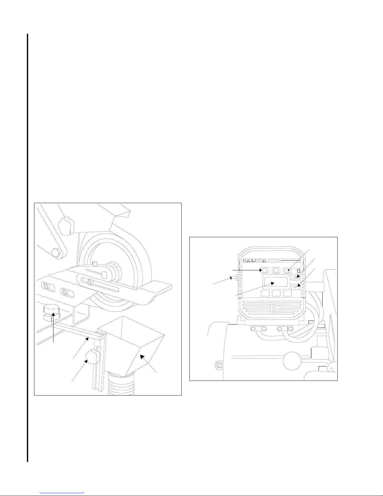
V acuum Connection
Operating Controls
NOTE: A variety of vacuum system options
are available. (Refer to Accessories section.)
The grinder uses a front mounted vacuum system.
Refer to Fgure 3. Install the vacuum system
components as follows:
1. Slide the support bracket into the channel
secured to belt grinder base. Install one knob
in the belt grinder base to secure the support
bracket.
NOTE: Refer to vacuum scoop exploded view,
Figure 11 when installing channel.
2. Slide the ducted scoop onto the support
bracket. Install remaining knob in the support
bracket to secure the scoop.
3. Connect hose to exhaust duct and secure with
a clamp.
Model J-4103
The ON/OFF switch for the Model J-4103 grinder is
located in a switch box mounted on the drive motor.
Model 4126AC
NOTE: Refer to Figure 4. Use only the inverter
controls defined in the following procedures. The
inverter is pre-programmed at the factory and
requires no further programming.The controls for
the Model 4126AC grinder are located on the
inverter. The ON/OFF switch is located on the left
side of the inverter. Start the grinder by setting the
ON/OFF switch to ON.
Press the FWD RUN pushbutton on the inverter
and set the speed using the up/down arrow keys
(to the right of the speed display). Press the up
arrow to increase speed; press the down arrow to
reduce speed. The display on the inverter shows
drive motor speed in revolutions per minute. Press
the STOP button on the inverter to stop the grinder.
Then set the ON/OFF switch to OFF.
STOP
Button
Up
FWD (Forward) Button
On/Off
Switch
Speed Display
(RPM)
Down
8
Clamping
Knob
Support
Bracket
Scoop
Clamping
Knob
Figure 3: V acuum Connection
Figure 4: Operating Controls
(Model 4126AC)
Electrical Connection
Refer to the Wiring Diagram section for wiring
information. Connection to electrical power should
be made by a qualified electrician. Observe local
electrical codes when connecting the machine.

Typical Uses for the Square Wheel Belt Grinder
Flat or angular
stock — Platen
setting is the perfect
angle for high speed,
precision, flat and
level grinding of
tools, knives, plastics, and other
materials. The platen
allows working to
very close tolerances. An adjustable
work rest is standard
on all models.
OPTIONAL FEA TURES
Shaping — For
grinding and finishing cylindrical
shapes. The yoke
surface conforms to
the shape of the
surface to produce
an even, smooth
finish without the
danger of scarring.
Excellent for tool
post applications.
Roughing — Serrated contact wheel is
used for removing
heavy stock, cleaning
up a weld or snagging a casting. This
durable 8-inch
diameter wheel is
used extensively for
hollow grinding and
profiling knives and
other culinary tools.
It is standard equipment on all models.
Contouring — Grind
difficult, hard to
reach areas with the
3-inch by 2-inch or 11/2 inch by 2-inch
diameter contact
wheels. Contours
and shapes unique
parts like propellers
and metal furniture.
Internal contouring
— The air-cushioned
dead head is for use
on very small radius
grinding. When
connected to a
source of shop air
(80-90 psi), the belt
rides on a cushion of
air to decrease head
and belt wear. The
dead head is easy to
use, and adapts to
any of the available
radius tips.
Internal contouring with
small wheel — This small
wheel accessory is
designed for hard to reach
places. Includes 5/8-inch,
70 durometer contact
wheel. Available contact
wheels are 1/2-inch, 3/4inch, and 1-inch.
Polishing — The
buffing pad is perfect
for satin finish or high
gloss polishing. The
fine, close stitched
burring pads are ideal
for metal and plastic
9
Finishing — The nylon
reinforced, silicone
carbide wheel is
perfect for polishing
and deburring. It
applies a high luster
finish on rough surfaces and is excellent
for steel, iron, or
aluminum.

10
Maintenance
Cleaning
Shutoff the machine before cleaning. Keep the exterior
of the machine clean and free of chips. Use a brush for
cleaning. Periodically empty grinding dust and particles
from the dust collection system.
Lubrication
Lubrication of the grinder is not required. The drive
motor and contact wheel are fitted with sealed bearings.
Replacement of Contact Wheel
WARNING: BE SURE TO SET ON/OFF SWITCH TO
OFF TO A VOID PERSONAL INJURY.
1. Refer to Figure 5. Lower the tension lever to release
belt tension.
2. Loosen upper guard knob and swing guard back for
clearance.
3. Loosen the contact wheel shaft clamping screw on
the head casting.
4. Remove the contact wheel assembly .
5. Remove retaining rings from wheel shaft.
6. Remove shaft and wheel bearings.
7. Install bearings in replacement contact wheel.
8. Install shaft and secure with retaining rings.
9. Install contact wheel shaft in head casting.
10. Tighten clamping screw .
1 1. Lift tension lever to set belt tension.
12. Lower and adjust position of upper guard. Tighten
the upper guard knob.
Tension
Lever
Upper Guard
Installation of Platen
WARNING: BE SURE TO SET ON/OFF SWITCH
OFF TO A VOID PERSONAL INJURY.
1. Refer to Figure 6. Lower the tension lever to
release belt tension.
2. Loosen upper guard knob and swing guard
back for clearance.
3. Loosen the contact wheel shaft clamping screw
on the head casting.
4. Remove contact wheel (see Replacement of
Contact Wheel).
5. Install pivot shaft of platen in head casting.
Position platen as desired.
A. For grinding flat or angular work
pieces, position the platen with the platen
surface facing outward.
B. For grinding of cylindrical work pieces,
position the platen with the “yoke” side
facing outward.
C. Set at desired angle.
6. Tighten clamping screw .
7. Lift tension lever to set belt tension.
8. Lower and adjust position of upper guard.
Tighten the upper guard knob.
Platen
Clamping
Screw
Pivot
Shaft
Upper Guard Knob
Figure 5: Replacement of Contact Wheel
Clamping
Screw
Contact
Wheel
Head
Casting
Work
Rest
Figure 6: Installation of Platen

Replacement of Grinding Belt
WARNING: DO NOT OPERA TE THE MACHINE WITH
THE SIDE P ANEL OPEN. DISCONNECT ELECTRICAL POWER TO THE MACHINE BEFORE PERFORMING ANY MAINTENANCE.
1. Refer to Figure 7. Lower the belt tension lever to
release tension on the belt.
2. Loosen the knob on the left side of the machine
and raise upper guard. Turn the knob on the side
panel and lower the side panel.
3. If required, loosen work rest to provide clearance
for belt removal.
4. Remove the belt from the drive wheel, idler
wheel, and contact wheel. Install the replacement belt over the drive wheel, idler wheel, and
contact wheel.
5. Raise the belt tension lever to tighten the belt
against the wheels. Tighten the belt until it is just
taut. A moderate tension will provide faster
cutting, longer belt life, and better tracking. Do
not over-tension the belt.
6. Check belt tracking by spinning the drive wheel
by hand. Adjust tracking if required. (Refer to
Checking Belt Tracking.)
2. Spin the drive wheel by hand and check tracking of the belt. If the belt tracks either right or
left, adjustment is required.
3. Use an Allen wrench to change the alignment
of the idler wheel. Turn the idler adjustment
screw clockwise to cause the belt to track right.
Turn the idler adjustment screw counterclockwise to cause the belt to track left.
4. Close side panel and secure by turning the
knob on the panel. Lower the upper belt guard
and secure with the knob on the left side of the
grinder.
5. Connect electrical power and start the grinder.
Check belt tracking (the belt should be centered on the contact wheel.
6. If required, adjust belt tracking to center the
belt on the contact wheel. Turn the idler
adjustment screw clockwise to move the belt to
the right. Turn the idler adjustment screw
counterclockwise to move the belt to the left.
7. If the belt does not track properly, increase belt
tension. Repeat steps 1 through 6.
Upper
Idler Wheel
Grinding
Belt
Contact
Wheel
Figure 7: Replacement of Grinding Belt
Guard
Drive
Wheel
Side
Panel
Checking Belt Tracking
WARNING: DO NOT OPERATE THE MACHINE WITH
THE SIDE P ANEL OPEN. DISCONNECT ELECTRICAL POWER TO THE MACHINE BEFORE PERFORMING ANY MAINTENANCE.
1. Loosen the knob on the left side of the machine
and raise upper guard. Turn the knob on the side
panel and lower the side panel.
Replacement of Inverter
WARNING: DISCONNECT ELECTRICAL POWER
TO THE MACHINE BEFORE PERFORMING ANY
MAINTENANCE.
1. Disconnect electrical power.
2. Remove access panel on front of inverter.
Disconnect inverter wiring.
3. Remove four screws (1) and four nuts (6) from
inverter (2). Separate inverter (2) from mount
(4).
4. Install replacement inverter (2) and secure with
four screws (1) and four nuts (6).
5. Connect electrical wiring (refer to Wiring
Diagram section for connections).
6. Start belt grinder and check for proper operation.
NOTE: Inverter is pre-programmed at the factory,
further programming is not required.
11

Wiring Diagrams
Model J-4103
12
Model 4126AC

T roubleshooting
Problem Probable Cause Suggested Remedy
Poor Tracking 1. Improper belt splice. 1. Check belt for irregular seam or shape.
2. Excessive belt tension. 2. Set tension so belt is just taut.
3. Insufficient belt tension. 3. Set tension so belt is just taut.
4. Worn contact surfaces. 4. Check elastomer on contact wheels.
Replace worn wheels.
5. Misaligned contact surfaces. 5. Check alignment of drive wheel and
contact wheels. The drive pulley and
contact wheel must be aligned. To
adjust drive wheel, loosen set screws
and move drive wheel in or out on
motor shaft as required. To adjust
contact wheel, loosen shaft clamping
screw and move contact wheel in or out
as required.
6. Lack of crown on drive wheel. 6. Check for 1/16-inch crown. Replace
drive wheel if crown is not present.
7. Worn bearings. 7. Check all bearings for overheating or
damage. Replace worn or damaged
bearings.
Slack Belt 1. Insufficient belt tension. 1. Set tension so belt is just taut.
Contact Wheel Wear 1. Excessive belt tension. 1. Set tension so belt is just taut.
2. Grinding in one area on belt. 2. Use entire work surface of belt when
ever possible.
3. Excessive grinding deposits 3. Periodically clean interior of grinder.
on belt and debris in machine.
Short Belt Life 1. Excessive grinding pressure. 1. Allow the belt to do the cutting.
Excessive pressure dulls the belt and
removes the grit from the belt.
Replacement Parts
This section provides exploded view illustrations that show the replacement parts for the JET Models J-4103 and
J-4126AC Square Wheel Belt Grinder. Also provided are part s listings that show part number , description and
quantity . The item numbers on the illustration relate to the item number in the facing page of the p arts listing.
Order replacement parts from:
WAL TER MEIER (Manufacturing) Inc.
427 New Sanford Road
LaVergne, Tennessee 37086
Phone: 800-274-6848
13
Identify the replacement part by the part number shown in the parts listing. Be sure to include the model
number and serial number of your machine when ordering replacement parts to assure that you will receive the
correct part.

14
5
4
Exploded View - Square Wheel Belt Grinder

Ref. Part
5508076 Motor, 1 HP, 3-Phase (J-4126AC only) 1
No. Number Description Qty.
31 9066821 Motor & Switch, 1 HP , 1-Phase (J-4103) 1
30 5541241 Switch (Model 4103 only) 1
34 9128671 Bolt, Hex Head, w/Nylock 3/8-16 x 3/4 4
33 9070781 Nut, Allen, 5/16-18 1
32 9070361 Knob, Hand 1
37 9054541 Set Screw, Socket Head 5/16-18 x 1/2 2
36 504451 1 Pulley, Drive 1
35 91 14320 Key, 3/16 x 3/16 x 1-1/4 1
40 9070381 Latch, Cam 1
39 5077041 Lock Washer , 5/16 2
38 5630451 Screw, Socket Head Hex 5/16-18 x 1-1/2 1
43 505531 1 Door 1
42 5507583 Washer, Nylon 5/16 2
41 5630061 Nut, Hex, 5/16-18 1
46 9057461 Washer, Flat 0.26 x 0.63 x 0.06 1
45 J-5044630 Guard Flap Assembly 1
44 9070371 Knob, Hand 1
49 J-5541030 Main Frame Assembly 1
48 J-5046540 Casting, Idler Housing 1
47 5046600 Tracking Leader Assembly 1
15
5510943 Contact Wheel Assy, 8 x 2 Smooth, 50 Duro 1
5510942 Contact Wheel Assy, 8 x 2 Serrated, 50 Duro 1
1 5510944 Contact Wheel Assy, 10 x 2 Serrat, 90 Duro 1
No. Number Description Qty.
Ref. Part
Parts List - Square Wheel Belt Grinder
2 5044590 Contact Wheel Assy, 1-1/2 x 2 1
3 5044610 Contact Wheel Assy, 3 x 2 1
3A 9049821 Screw, Flat Head Cap 2
4 5507582 Idler Wheel 1
optional grit below) (10 piece minimum order) 1
5510947 Contact Wheel, 8 x 2 Smooth, 50 Duro 1
5510948 Contact Wheel, 10 x 2 Serrated, 90 Duro 1
5 9100331 Bearing 2
6 907401 1 Retaining Ring, Internal 2
7 9074081 Retaining Ring, External 2
8 5510946 Contact Wheel, 8 x 2 Serrated, 50 Duro 1
9 5053231 Shaft, 8 x 10 Wheel 1
10 9074381 Retaining Ring, External 1
1 1 911281 1 Abrasive Belt, 2 x 72, 50 Grit (Standard -
12 J-5044400 Platen Casting 1
13 J-5044410 Work Rest Casting 1
14 J-5044370 Head Casting 1
15 9128441 Screw, Socket Head Cap 3/8-16 x 1 1
16 5049990 Screw, Work Rest Machine 1
17 9129881 Screw, Socket Head Cap 3/8-16 x 5/8 2
18 9055361 Flat Washer, Nylon 1/2 I.D. x 1 O.D. 1
19 9129861 Scr, Socket Head Cap, Fll Thrd, 3/8-24 x 3 1
20 5046571 Bearing, Idler Housing 1
21 9055381 Flat Washer , Nylon, 3/8 2
22 9010271 O-Ring, 1/2 1
23 5044651 Cap, Idler Housing Pin 1
24 9133041 Set Screw, Socket Head 1/4-20 x 1/4 1
25 5046560 Lever, T ension 1
26 9133191 Set Screw, Nylon Tipped 5/16-18 x 3/4 1
27 9129561 Locknut, Hex, 3/8-24 1
28 905981 1 Roll Pin, 3/16 x 1-1/2 1
29 5053301 Shaft, Idler Pulley 1

Parts List - Inverter
16
Ref. Part
No. Number Description Qty.
1 5550874 Screw, Socket head 7
Cap, 10-32NF x 3/8
2 5507817 inverter (1ph, 120V, 50/60Hz) 1
5507818 Inverter (3ph, 220V , 50/60Hz)
5511447 Inverter (3ph, 440V , 50/60Hz)
3 9128571 Screw, Hex Head 1/2-13 x 1 1
4 5515215 Mount, Inverter 1
5 9119481 Terminal, Full Closed 1
Ref. Part
No. Number Description Qty.
6 5508073 Nut, Lock, 10-32 Nylock 4
7 5507934 Box, Switch 1
9 9119721 Spade, Female 16-14AWG 4
10 91 17401 Switch, T oggle 1
12 9085061 Dial, ON-OFF 1
13 9119071 Grip, Cord 2
14 5628371 Lock Washer, 1/2 1
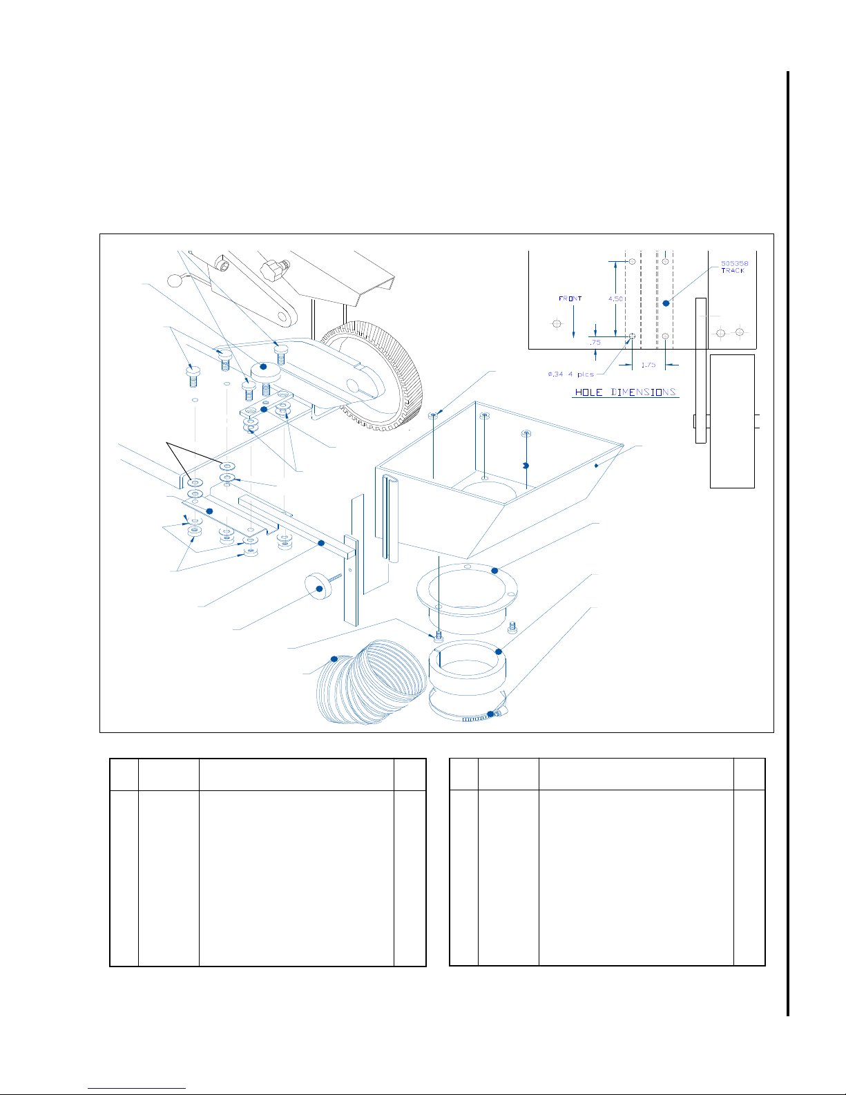
Accessories
Exploded View - Vacuum Scoop
A vacuum scoop connects the machine to the vacuum system. The mounting provisions for the scoop are
shown in the exploded view below.
15
7
14
13
10
11
10
9
8
7
Ref. Part
No. Number Description Qty.
1 5053531 Scoop Assembly 1
2 5052471 Adapter, Hose 1
3 5053601 Reducer, 4 x 3 in. 1
(Woodworkers)
505361 1 Reducer , 4 x 3 in. 1
(Metal Workers)
4 5507534 Clamp, Hose 3 in. 1
5 5507533 Hose, 3 x 5 in. 1
6 9128241 Screw, HH Cap 3
7 9070361 Knob 2
12
6
5
12
10
1
2
3
4
17
V acuum Scoop Exploded View
Ref. Part
No. Number Description Qty.
8 5053571 Rail 1
9 9032961 Lock Nut, Nylon Insert 4
10 905541 1 Washer , Nylon 8
1 1 5053581 Channel 1
12 9057391 Washer , Flat 2
13 905641 1 Nut, Hex Jam 3
14 9062111 Screw, SHCS (5/16-18 X 3/4) 2
15 9146801 Screw, SHCS Low Head 2
(5/16-18 X 1 1/2)

Accessories
Belt Grinder Pedestal
The optional pedestal enables the Square Wheel Belt
Grinder to be mounted in a free standing configuration
rather than on a work bench. The grinder is secured
to the pedestal using the four holes in the base of the
grinder - follow the below instructions.
Assembly of Pedestal
Unpacking
The grinding machine pedestal is shipped separately
from the grinding machine. Transport the shipping
containers to the installation site before unpacking.
Unpack the pedestal and grinding machine. Locate and
open the plastic bag containing four 5/16-18 socket
head cap screws. Verify that that there are two screws
1-inch long and two screws 1-3/4 inches long (Figure
16, View A).
Figure 15: Contouring Using Small
Diameter Contact Wheel
18
Securing the Pedestal
WARNING: BOLTING THE PEDESTAL TO THE
FLOOR IS STRONGL Y RECOMMENDED. THE
PEDESTAL IS BOLTED TO THE FLOOR TO
ELIMINA TE THE POSSIBILITY OF TIP-OVER
WHILE THE MACHINE IS BEING OPERA TED.
FAILURE T O DO SO CAN RESULT IN INJURY
TO THE OPERA T OR AND/OR OTHER NEARBY
PERSONNEL.
The pedestal has four mounting holes in its base.
Use these mounting holes to secure the pedestal to
the floor before installing the grinder. Shims should
be used to level the pedestal before the attaching
bolts are tightened.
Assembly
WARNING: THE MACHINE MOUNTING PLA TE IS
NOT CENTERED ON THE LEG OF THE PEDEST AL. THIS OFFSET EVENL Y DISTRIBUTES
THE WEIGHT OF THE GRINDING MACHINE.
MAKE SURE THE GRINDING MACHINE IS
CORRECTL Y POSITIONED AND SECURED T O
THE PEDEST AL BEFORE LEA VING THE MACHINE UNA TTENDED. FAILURE TO CORRECTL Y
POSITION AND SECURE THE MACHINE COULD
RESUL T IN THE MACHINE TIPPING OVER,
CAUSING INJURY TO PERSONNEL.
There are four mounting holes in the mounting plate on
the pedestal. The holes on the motor side of the machine
are approximately 20 inches apart. The holes on the
belt-guard side of the machine are located approximately
½-inch from the corners of the plate. When correctly
installed, all four screw holes in the machine base plate
and belt guard will align with the holes in the mounting
plate of the pedestal.
Mounting Procedure
A. Using two people or a hoisting device, lift the grind-
ing machine and set it on the pedestal. Align all
four screw holes in the machine base plate and
belt guard with the holes in the mounting plate of
the pedestal (Figure 16, View B).
B. Open the grinding belt guard door (Figure 16, View
C). Install two 5/16-18 x 1-inch long screws in the
base of the grinding belt guard. Install screws
finger-tight.
C. Install the two 5/16-18 x 1-3/4-inch long screws in
the screw holes on the motor side of the machine
base (Figure 16, View D). Tighten all four screws.

A
B
Belt Guard Holes
Approximately
2
3
Motor Side
Holes
20 inches
apart
1/2-inch from
corners
1
C
Install two 1inch long
screws
2
Ref. No. Part Number Description Qty.
1 J-524808 Pedestal 1
2 9062121 Socket Head Cap Screw (5/16-18 x 1) 2
3 5511051 Socket Head Cap Screw (5/16-18 x 1 3/4) 2
D
3
Install two
1 3/4-inch
screws
19
Figure 16: Assembly of Grinding Machine and Pedestal

WA LTER MEIER (Manufacturing) Inc.
427 New Sanford Road
LaVergne, T ennessee 37086
Ph.: 800-274-6848
www.waltermeier.com
 Loading...