

This .pdf document is bookmarked
Operating Instructions and Parts Manual
Belt (2x42”) and Disc (8”) Sander
Model J-41002
JET
427 New Sanford Road
LaVergne, Tennessee 37086 Part No. M-577004
Ph.: 800-274-6848 Revision C1 10/2018
www.jettools.com Copyright © 2014 JET

Warranty and Service
JET warrants every product it sells against manufacturers’ defects. If one of our tools needs service or repair, please
contact Technical Service by calling 1-800-274-6846, 8AM to 5PM CST, Monday through Friday.
Warranty Period
The general warranty lasts for the time period specified in the literature included with your product or on the official
JET branded website.
• JET products carry a limited warranty which varies in duration based upon the product. (See chart below)
• Accessories carry a limited warranty of one year from the date of receipt.
• Consumable items are defined as expendable parts or accessories expected to become inoperable within a
reasonable amount of use and are covered by a 90 day limited warranty against manufacturer’s defects.
Who is Covered
This warranty covers only the initial purchaser of the product from the date of delivery.
What is Covered
This warranty covers any defects in workmanship or materials subject to the limitations stated below. This warranty
does not cover failures due directly or indirectly to misuse, abuse, negligence or accidents, normal wear-and-tear,
improper repair, alterations or lack of maintenance. JET woodworking machinery is designed to be used with Wood.
Use of these machines in the processing of metal, plastics, or other materials outside recommended guidelines may
void the warranty. The exceptions are acrylics and other natural items that are made specifically for wood turning.
Warranty Limitations
Woodworking products with a Five Year Warranty that are used for commercial or industrial purposes default to a
Two Year Warranty. Please contact Technical Service at 1-800-274-6846 for further clarification.
How to Get Technical Support
Please contact Technical Service by calling 1-800-274-6846. Please note that you will be asked to provide proof
of initial purchase when calling. If a product requires further inspection, the Technical Service representative will
explain and assist with any additional action needed. JET has Authorized Service Centers located throughout the
United States. For the name of an Authorized Service Center in your area call 1-800-274-6846 or use the Service
Center Locator on the JET website.
More Information
JET is constantly adding new products. For complete, up-to-date product information, check with your local distributor
or visit the JET website.
How State Law Applies
This warranty gives you specific legal rights, subject to applicable state law.
Limitations on This Warranty
JET LIMITS ALL IMPLIED WARRANTIES TO THE PERIOD OF THE LIMITED WARRANTY FOR EACH PRODUCT.
EXCEPT AS STATED HEREIN, ANY IMPLIED WARRANTIES OF MERCHANTABILITY AND FITNESS FOR A
PARTICULAR PURPOSE ARE EXCLUDED. SOME STATES DO NOT ALLOW LIMITATIONS ON HOW LONG AN
IMPLIED WARRANTY LASTS, SO THE ABOVE LIMITATION MAY NOT APPLY TO YOU.
JET SHALL IN NO EVENT BE LIABLE FOR DEATH, INJURIES TO PERSONS OR PROPERTY, OR FOR
INCIDENTAL, CONTINGENT, SPECIAL, OR CONSEQUENTIAL DAMAGES ARISING FROM THE USE OF OUR
PRODUCTS. SOME STATES DO NOT ALLOW THE EXCLUSION OR LIMITATION OF INCIDENTAL OR
CONSEQUENTIAL DAMAGES, SO THE ABOVE LIMITATION OR EXCLUSION MAY NOT APPLY TO YOU.
JET sells through distributors only. The specifications listed in JET printed materials and on official JET website are
given as general information and are not binding. JET reserves the right to effect at any time, without prior notice,
those alterations to parts, fittings, and accessory equipment which they may deem necessary for any reason
whatsoever. JET
Product Listing with Warranty Period
90 Days – Parts; Consumable items
1 Year – Motors; Machine Accessories
2 Year – Metalworking Machinery; Electric Hoists, Electric Hoist Accessories; Woodworking Machinery used
for industrial or commercial purposes
5 Year – Woodworking Machinery
Limited Lifetime – JET Parallel clamps; VOLT Series Electric Hoists; Manual Hoists; Manual Hoist
Accessories; Shop Tools; Warehouse & Dock products; Hand Tools; Air Tools
NOTE: JET is a division of JPW Industries, Inc. References in this document to JET also apply to JPW Industries,
Inc., or any of its successors in interest to the JET brand.
®
branded products are not sold in Canada by JPW Industries, Inc.
2

Table of Contents
Warranty and Service .................................................................................................................................... 2
Table of Contents .......................................................................................................................................... 3
Warning ......................................................................................................................................................... 4
Introduction.................................................................................................................................................... 6
Specifications ................................................................................................................................................ 6
Features and Terminology ............................................................................................................................ 7
Unpacking ..................................................................................................................................................... 8
Contents of the Shipping Container .......................................................................................................... 8
Assembly ....................................................................................................................................................... 9
Installing Belt Table ................................................................................................................................... 9
Installing Dust Chute ................................................................................................................................. 9
Installing Disc Table ................................................................................................................................ 10
Installing Miter Gauge.............................................................................................................................. 10
Installing Tension Handle ........................................................................................................................ 10
Grounding Instructions ................................................................................................................................ 11
115 Volt Operation ................................................................................................................................... 11
Adjustments ................................................................................................................................................ 12
Tilting the Belt Table ................................................................................................................................ 12
Tilting the Disc Table ............................................................................................................................... 12
Use of the Miter Gauge ........................................................................................................................... 13
Belt Platen ............................................................................................................................................... 13
Abrasive Belt Replacement ..................................................................................................................... 14
Tracking the Abrasive Belt ...................................................................................................................... 14
Abrasive Disc Replacement .................................................................................................................... 15
Aluminum Disc Removal ......................................................................................................................... 15
Operation..................................................................................................................................................... 16
Starting and Stopping the Sander ........................................................................................................... 16
Belt and Disc Movement.......................................................................................................................... 16
Typical Operations ................................................................................................................................... 16
Extension Cords ...................................................................................................................................... 11
Maintenance ................................................................................................................................................ 18
Replacement Parts ...................................................................................................................................... 18
Troubleshooting .......................................................................................................................................... 19
Assembly Drawing ................................................................................................................................... 20
Parts List .................................................................................................................................................. 21
3

Warning
1. Read and understand the entire owner’s manual before attempting assembly or operation.
2. Read and understand the war nings p osted on the m achine an d in t his m anua l. F ailure t o com pl y with
all of these warnings may cause serious injury.
3. Replace the warning labels if they become obscured or removed.
4. This sander is designed and inten ded for use b y properly trained and experienc ed personnel o nly. If
you are not familiar with the proper and safe operat ion of a sander, do not use unti l proper training
and knowledge have been obtained.
5. Do not use this sander for other than its i ntended use. If used for other purpos es, JET dis claims any
real or implied warranty and holds itself harmless from any injury that may result from that use.
6. Always wear approved safe ty glass es/f ace s hields while usin g this san der. Ever yday e yeglas ses onl y
have impact resistant lenses; they are not safety glasses.
7. Before operating th is sander, rem ove tie, rings, watc hes and other jewelr y, and roll sleeves up past
the elbows. Remove al l loo se clothi ng and c onfin e lon g hair. N on-sl ip foot wear or anti-sk id f loor str ips
are recommended. Do not wear glo ves.
8. Wear ear protectors (plugs or muffs) during extended periods of operation.
9. Do not operate this machine while tired or under the influence of drugs, alcohol or any medication.
10. Make certain the switch is in the OFF position before connecting the machine to the power supply.
11. Make certain the machine is properly grounded.
12. Make all machine adjustments or maintenance with the machine unplugged from the power source.
13. Remove adjusting keys and wrenches. Form a habit of checking to see that keys and adjusting
wrenches are removed from the machine before turning it on.
14. Keep safety guards in place at all times when the machine is in use. If rem oved for maintenance
purposes, use extreme caution and replace the guards immediately.
15. If there is a tendency for the m achine to tip over or move during operation, su ch as when sanding
long or heavy boards, the machine must be securely fastened to a supporting surface.
16. Check damaged parts. Before further use of the machine, a guard or other part that is damaged
should be carefully checked to determine that it will operate properly and perform its intended
function. Check f or alignment of m oving parts, bindin g of moving parts , breakage of parts, m ounting
and any other conditions that may affect its oper ation. A guard or other part th at is damaged shoul d
be properly repaired or replaced.
17. Provide for adequate space surrounding work area and non-glare, overhead lighting.
18. Keep the floor around the machine clean and free of scrap material, oil and grease.
19. Keep visitors a safe distance from the work area. Keep children away.
20. Make your workshop child proof with padlocks, master switches or by removing starter keys.
21. Give your work undivided a ttention. Look ing around, c arrying o n a conversati on and “hors e-pla y” are
careless acts that can result in serious injury.
22. Maintain a balanced stanc e at all tim es so that you d o not fall or lean against the abrasives or oth er
moving parts. Do not overreach or use excessive force to perform any machine operation.
23. Use the r ight to ol at the c orr ect spee d and feed rate. Do n ot for ce a t ool or att achm ent to d o a j ob f or
which it was not designed. The right tool will do the job better and safer.
24. Make sure the abrasive belt is running in the proper direction. When disc sanding, place the
workpiece against the downward rotating part of the abrasive disc.
4

25. This machine can be use d for sanding wood or m etal products. Howev er, combining wood dus t and
metal filings can create a fire hazard. Make sure your dust collector is free of wood dust deposits
before processing metal products.
26. Use recommended accessories; improper accessories may be hazardous.
27. Maintain tools with care. Follow instructions for lubricating the machine and changing accessories.
28. Abrasive discs must be stored in a controlled environment. Relative humidity should be 35% to 50%
and the temperature should be between 60° and 80° Fahrenheit. Failure to do this could cause
premature disc failure.
29. Examine the f ace of the abrasive disc or belt c arefully. Excessive sanding that wears down to the
backing material c an te ar the disc /belt. Never use an abras ive which s ho ws back ing, n ick s or c uts on
the surface or edge, or damage due to creasing or poor handling.
30. T ur n of f the machine before clea n ing. Us e a br ush or compres sed air to remove c hips or d ebr is — do
not use your hands.
31. Never leave the machine running unattended. Turn the power off and do not leave the machine until it
comes to a complete stop.
32. Do not use the sander in wet or damp locations.
33. Remove loose items and unnecessary work pieces from the area before starting the machine.
WARNING: This product can expose you to chemicals including lead and cadmium which are
known to the State of California to cause cancer and birth defects or other reproductive harm, and
phthalates which ar e known to the St ate of Ca lifornia to cause b irt h def ec ts or other reproduc ti ve h ar m .
For more information go to http://www.p65warnings.ca.gov.
WARNING: Some dust, fumes and gases created by power sanding, sawing, grinding, drilling,
welding and other constru ction activities contain chem icals known to the State of California to cause
cancer and birth defects or other reproductive harm. Some examples of these chemicals are:
• lead from lead based paint
• crystalline silica from bricks, cement and other masonry products
• arsenic and chromium from chemically treated lumber
Your risk of exposure varies, depending on how often you do this type of work. To reduce your
exposure to these chem icals, work in a well-venti lated area and wor k with approv ed safety equipm ent,
such as dust masks that are specifically designed to filter out microscopic particles. For more
information go to http://www.p65warnings.ca.gov/ and http://www.p65warnings.ca.gov/wood.
Familiarize yourself with the following safety notices used in this manual:
This means that if precautions are not heeded, it may result in minor injury and/or
possible machine damage.
This means that if precautions are not heeded, it may result in serious injury or possibly
even death.
- - SAVE THESE INSTRUCTIONS - -
5

Introduction
This manual is provided by JET covering the safe operation and maintenance procedures for a JET
2x42x8 Belt and Disc Sander. This manual contains instructions on installation, safety precautions,
general operating procedures, maintenance instructions and parts breakdown. This machine has been
designed and constructed to provide consistent, long-term operation if used in accordance with
instructions set f orth in this manual. If there are a ny questions or comm ents, please contact either your
local supplier or JET. JET can also be reached at our web site: www.jettools.com.
Specifications
Model Number .................................................................................................................................... J-41002
Stock Number ..................................................................................................................................... 577004
Belt Size (in.)(LxW) ............................................................................................................................... 42 x 2
Belt Speed (SFPM) ................................................................................................................................. 3100
Disc Size (in.) ................................................................................................................................. 8 diameter
Disc Speed (RPM) .................................................................................................................................. 3450
Motor ......................................................................................................................... 3/4HP, 1Ph, 115V, 6.2A
Belt Table Size (in.)(LxW) ..................................................................................................................... 10 x 6
Disc Table Size (in.)(LxW) ........................................................................................................ 10-3/4 x 7-1/2
Disc Table Tilt (deg.) ............................................................................................................................ 0 to 45
Dust Chutes (in.) .......................................................................................................... two @ 1-1/2 diameter
Overall Size (in.)(WxDxH) ............................................................................................... 20-1/2 x 22-3/4 x 20
Approximate Net Weight (lbs.) .................................................................................................................... 58
Approximate Shipping Weight (lbs.) ............................................................................................................ 64
The above specif ic atio ns were c ur rent at the time this manual was publishe d, but bec ause of our policy of
continuous improvem ent, JET reserves the right to change specif ications at any time and without prior
notice, without incurring obligations.
6

Features and Terminology
7

Unpacking
Open shipping container and check for shipping
damage. Report any damage immediately to
your distributor and shipping agent. Do not
discard any sh ipping material u ntil the sander is
assembled and running properly.
Compare the contents of your container with t he
following parts list to make sure all parts are
intact. Missing part s, if any, should be reported
to your distributor. Read the instruction manual
thoroughly for assembly, maintenance and
safety instructions.
Contents of the Shipping Container
1 Belt and Disc Sander
1 Belt Table
1 Disc Table with trunnions
1 Miter Gauge
1 Dust Chute
6 Phillips Pan Hd. Machine Screws, 3/16x3/8”
3 Handles
3 Flat Washers, 3/8”
1 Tension Handle
1 Hex Nut, 1/4”
3 Hex Wrenches, 3, 4 and 6mm
1 Owner's Manual
1 Warranty Card
Read and understand the entire contents of this manual before attempting set-up
or operation! Failure to comply may cause serious injury.
8

Assembly
Tools needed for assembly:
• 10mm open-end wrench
• Cross-point (Phillips) screwdriver
• Combination square, or similar angle
measuring device.
Sander must be unplugged
from power source during assembly.
Remove the protecti ve c oat ing f r om the s urfaces
of the sander and from any loose parts. This
coating may be removed with a soft cloth
moistened with kerosene (do not use acetone,
gasoline or lacquer thinner for this purpose).
After cleaning, cover the table surfaces with a
good quality paste wax.
Leave enough space aro und the sander f or long
workpieces and for general maintenance.
If needed, the sander can be bo lted to a table or
workbench using the holes in the base. If the
sander has a tendency to walk or slide during
operation, it must be bolted to a supporting
surface.
Installing Belt Table
1. Unscrew the stud. See Figure 1.
2. Position the bracket of the belt table over the
holes in the cas ting as shown, and re-instal l
the stud into its hole.
3. Plac e a flat washer onto a handle, and insert
the handle through the table bracket and
into the hole. Scre w the handle all the way
into the hole.
NOTE: The handle is spring loaded; screw
the handle in by rotatin g clock wise, then pu ll
outward on the handle. Rotate the handle
back to position, then release it, making sure
it seats itself upon the pin. Continue the
process until the handle is tightened in the
hole.
Installing Dust Chute
The sander has two 1- 1/2” diameter dust chutes.
The dust chute for the belt is located on the belt
cover. The dust chute for the disc should be
installed as shown in F igure 2, using the six (6)
pan head machine screws that are provided.
Figure 1
The dust chutes can b e connected to a vac uum
system to collect dust particles.
Figure 2
9
Installing Disc Table
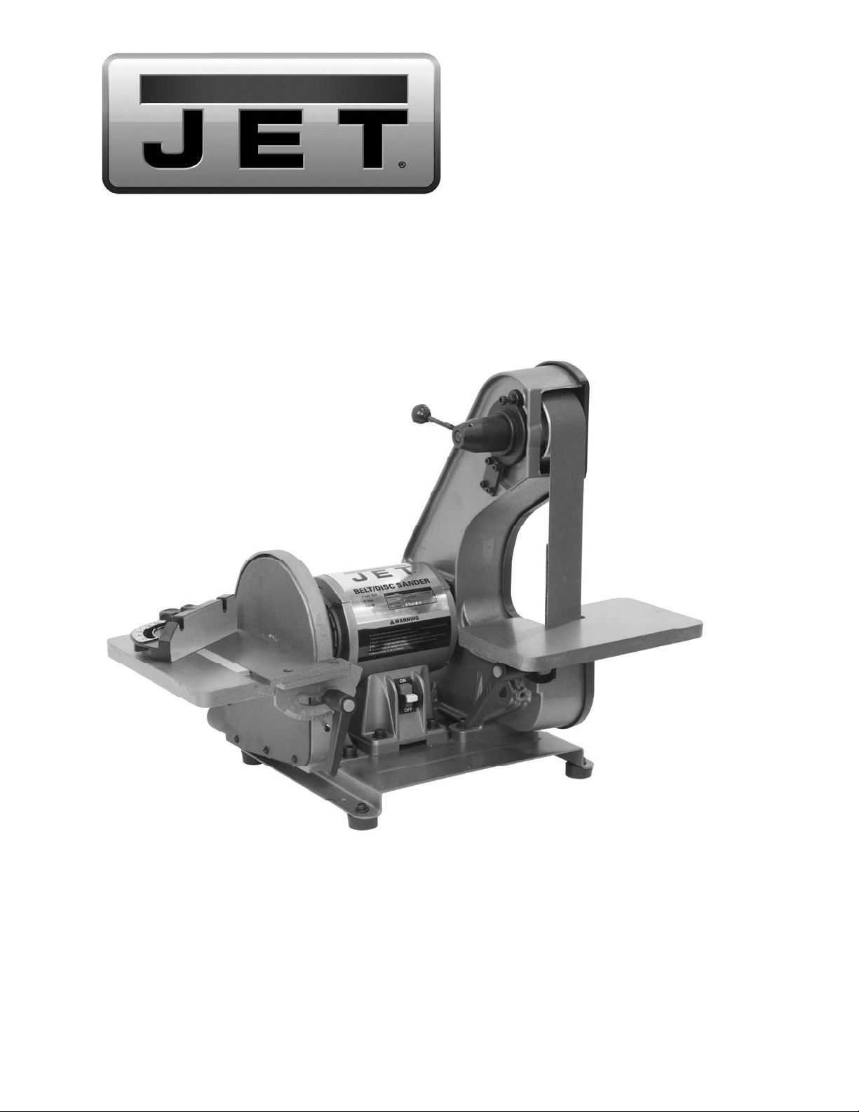
1. Position the disc table at an angl e, as s ho wn
in Figure 3, and slide the t a ble o n s o that th e
trunnion slots fit over the raised tracks on
the disc guard.
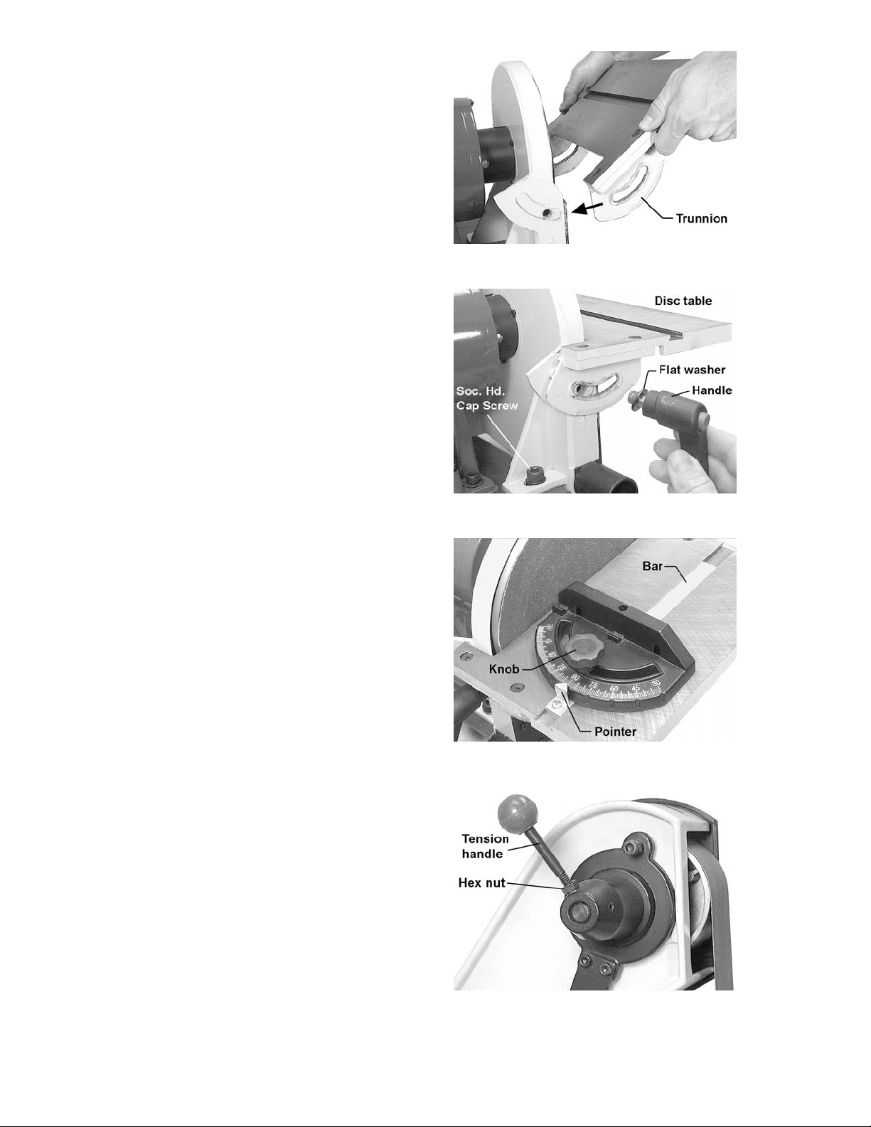
2. Install a flat washer onto each of the two
remaining handles. I ns ert the handle into the
holes through the left and right trunnions.
See Figure 4.
3. The gap between the sandin g disc and the
disc table should be a m aximum of 1/16”. If
it is larger than this, loosen the two socket
head cap screws on th e disc guard (one is
shown in Figure 4) and sli de the disc guard
to achieve this gap measurement.
4. When finished, tighten the t wo socket head
cap screws securely.
Figure 3
Figure 4
Installing Miter Gauge
Insert the miter gauge bar into one end of the
miter slot in the disc table. See Figure 5.
The miter gauge can be used in either d irection
in the slot to achieve the most effective
positioning of the workpiece against the abrasive
disc.
Installing Tension Handle
1. Place the 1/4” hex nut onto the threads of
the tension handle.
2. Screw the tension handle into the hole on
the hub, then tighten the h ex nut aga inst the
hub. See Figure 6.
Figure 5
Figure 6
10

Grounding Instructions
This machine must be
grounded while in use to protect the operator
from electric shock.
In the event of a malfunction or breakdown,
grounding provides a path of least res istance f or
electric current to reduce the risk of electric
shock. This tool is equip pe d with an elec tric cor d
having an equipment-grounding conduc tor and a
grounding plug. The plug must b e ins er te d int o a
matching receptacle that is properly installed
and grounded in accordanc e with all loc al codes
and ordinances.
Do not modify the plug pr ovided. If it will not fit
the outlet, have t he proper outlet installed b y a
qualified electrician.
Improper connection of the equipmentgrounding conductor can result in a risk of
electric shock. The conductor, with insulation
having an outer surface that is green with or
without yellow stripes, is the equipmentgrounding conductor. If repair or replacement of
the electric cord or plug is necessary, do not
connect the equipment-gr ounding conductor to a
live terminal.
Check with a qualified electrician or service
personnel if the grounding instructions are not
completely understood, or if in doubt as to
whether the tool is proper ly grounded. Use only
three wire extension cords that ha ve three- prong
grounding plugs and three-pole receptacles t hat
accept the tool’s plug.
115 Volt Operation
As received from the factory, your sander is
ready to run at 115 volt ope ration . T his s an der is
intended for use on a circuit that has an outlet
and a plug that looks like the one illustrated in
Figure 7.
A temporary adapter, l ike the adapter in Figure
8, may be used to connect this plug to a twopole receptacle, as shown in Figure 8, if a
properly grounded outlet is not available. The
temporary adapter should only be used until a
properly grounded outlet can be installed by a
qualified electrician. This adapter is not
applicable in Canada. The green color ed rigid
ear, lug, or tab, extending from the adapter,
must be connected to a perm anent ground such
as a properly ground ed outlet box, as shown in
Figure 8.
Figure 8
Extension Cords
Use proper extension c ords . Make sur e the cord
rating is suitable for the amperage of the
machine’s motor. An un dersized cord will cause
a drop in line volt age resulting in loss of power
and overheating.
Use the chart in Figure 9 as a general guide in
choosing the correc t size cord. The sm aller the
gauge number, the heavier the cord.
Recommended Gauges (AWG) of Extension Cords
Extension Cord Length *
25
50
75
100
150
200
Amps
< 5 16 16 16 14 12 12
5 to 8 16 16 14 12 10 NR
feet
feet
feet
feet
feet
feet
8 to 12 14 14 12 10 NR NR
12 to 15 12 12 10 10 NR NR
15 to 20 10 10 10 NR NR NR
21 to 30 10 NR NR NR NR NR
*based on limiting the line voltage drop to 5V at 150% of the
rated amperes.
NR: Not Recommended.
Figure 7
11
Figure 9
Adjustments
Tilting the Belt Table
The belt table tilts from zero (hor izonta l) do wn to
45°.
1. Loosen the handle and adjust the table into
desired position.
2. Check the angle with a machinist’s
protractor or similar measuring device that
has the required angle. Figure 10 shows a
square being used to confirm the zero, or
horizontal, position . Place the square flat on
the table and against the belt. Push against
the belt until the square is against the
platen.
3. Make any adjustm ents to the table angl e as
necessary until it is square with the belt.
4. Tighten the handle securely.
To avoid trapping the
workpiece or fingers between the table and
abrasive belt, the table edge should be
positioned a maximum of 1/16” from the
abrasive belt.
Tilting the Disc Table
The disc table tilts from zero (horizontal) down to
45°.
1. Loosen both handles and adjust the table
until the indicator lines up with the desired
angle on the scale. It is a good idea to
confirm this angle using your angle
measuring device placed flat upon the tab le
and against the abrasive disc.
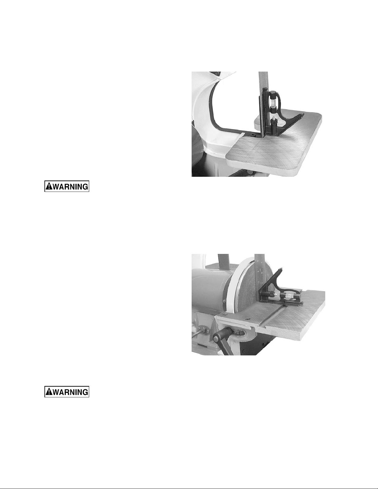
2. Figure 11 shows a square being used to
confirm the zero, or hor izo n tal p os it ion of the
disc table.
3. Make any necessary adjustments to the
table angle. If the table is square with the
disc but the angle indicator needs slight
adjustment, loosen the screw on the
indicator and shift the indicator as needed.
Re-tighten the screw.
4. Tighten both handles securely.
To avoid trapping the
workpiece or fingers between the table and
abrasive disc, the table edge should be
positioned a maximum of 1/16” from the
abrasive disc.
Figure 10
Figure 11
12
Use of the Miter Gauge
The miter gauge is used to sand accurate
angles on workpieces. When using the miter
gauge on the horizonta l table position, you can
sand a single angle. By tilting the disc table and
using the miter gauge in combination with the
table tilted, it is possible to sand compound
angles as well.
The miter gauge rotates to 30° for bevel
sanding. Loosen the k nob and rotate the gauge
body until the pointer lines up with the desired
angle on the scale.
Use a square to confirm that the m iter gauge is
set at 90° (perpendicul ar to the d isc ). See Figure
12. If slight adjustment is needed:
1. Loosen the knob.
2. Adjust the miter gauge body unt il it is flush
with the square, and the sq uare is flush with
the disc.
3. Tighten the knob.
4. Loosen the screw on the p ointer and adjust
the pointer until it aligns with 90° on the
scale.
5. Tighten the screw on the pointer.
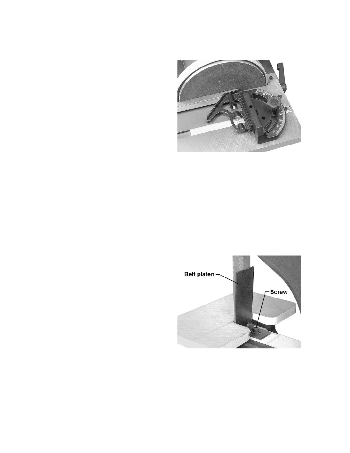
Belt Platen
The belt platen (Figure 13) is used to properly
support the workpiece while sandi ng. The plate n
is constructed of heavy steel to provide
adequate support.
The platen should be adjusted so it is almost
touching the back of the abrasive belt. Loosen
the socket head cap sc rew and adjus t the p laten
to the desired position. Tighten the screw to
secure the platen.
Figure 12
The platen can be rem oved for operations such
as stripping, cont our sanding, polishing or ot her
special operations. To remove the platen,
remove the socket head cap screw and washer.
Be sure to re-install the platen to perform
operations where support of the belt is required.
13
Figure 13

Abrasive Belt Replacement
1. Unplug the Sander from the power source.
2. Unscrew and remove the two k nobs on the
belt cover.
3. Remove the belt cover.
4. Rotate the tension handle (Figure 6) to
loosen the belt, and remove the old belt from
around the wheels.
5. Install the new belt around the wheels.
IMPORTANT: Some sanding belts have a
directional arrow printed on the inside of the belt.
In these cases, the be lt must be instal led so the
directional arro w is in the s am e direction that t he
machine is running. Refer to the rotation arrow
on top of the belt cover.
6. Install the belt cover and the two knobs.
7. Start the sander and check the belt trac king
before sanding operations (See “Tracking
the Abrasive Belt”).
Tracking the Abrasive Belt
“Tracking” refers to the manner in which the
abrasive belt is pos itioned on the wheels during
operation. The belt should remain in vertical
position without s hifting to one s ide or the other
of the wheel. If any shifting occurs, the belt
needs to be tracked properly, as follows:
1. Disconnect sander from power source.
2. Remove the side cover, and m ake sure the
belt is placed evenly over the center of the
wheels. Loosen the tension and re-position
the belt if necessary. Re-install the side
cover.
3. Move the belt by rotating the dis c with your
hand (do not turn on the power yet).
Observe the movement of the belt on the top
wheel.
4. If the belt slips to one side or the other,
loosen the hex nut (Figure 14) with a 10mm
open-end wrench.
5. Rotate the trac king screw ( Figure 14) with a
5mm hex wrench. If the belt is slid ing toward
the right, rotate the screw clockwise. If the
belt is sliding toward the left, rotate the
screw counterclockwise.
6. Continue this pr ocedure in small inc rements
until the belt is tracking properly when
moved by hand.
7. Re-connect the sander to power, and c ycle
the on/off switch quick ly to doub le chec k the
tracking.
Figure 14
8. Re-connect the sander to power, and c ycle
the on/off switch quick ly to doub le chec k the
tracking.
9. Make further adjustments as needed.
10. Tighten the hex nut to secure the setting.
14

Abrasive Disc Replacement
1. Unplug the sander from the power source.
2. Remove the dust cover and the disc table.
To remove the disc table, remove the
handles then tilt t he disc table upward while
pulling it away from the disc.
3. Peel off the old abrasive disc.
4. Thoroughl y clean the alum inum dis c surface
using naptha or a similar non-flammable
solvent that will dry film- free.
5. Pull the protective backing half-way off the
new abrasive disc.
6. Car efull y positio n the ne w abrasi ve disc so it
is centered accurately on the aluminum disc.
7. When accur ately centered, remove the rest
of the protective backing and press the
abrasive disc firmly against the aluminum
disc so complete adhesive contact is made.
8. Re-install dust cover and table.
9. Reconnect sander to power source.
Aluminum Disc Removal
The aluminum disc can be easily removed if
needed; for example, to facilitate cleaning the
aluminum disc when replacing abrasive discs.
1. Unplug sander from the power source.
2. Remove the disc table and the dust chute.
3. Rotate the disc until the set screw is
accessible through the opening behind the
disc guard. See Figur e 15. You m ay need to
loosen the socket head cap screws (see
Figure 4) on the guard and shift it forward i n
order to clear the set screw.
4. Loosen the set screw with a 3mm hex
wrench, and pull the aluminum disc off the
motor shaft.
5. W hen re-mounting the al uminum disc, make
sure the key is properly seated in the
keyway on the m otor shaft. Tighten the set
screw firmly when the disc has been
mounted.
Figure 15
15

Operation
This sander is intended for dry sanding of
metals. Do not use lubricants.
Do not sand or polish
magnesium; it may creat e a fire haza rd. Also,
do not sand very small or very thin
workpieces that cannot be safely controlled.
Starting and Stopping the Sander
The on/off switch is located on the side of the
motor housing. Move the switch upward to the
ON position to s tart the s ander. Move the switch
downward to the OFF position to stop the
sander.
When the sander is not being used, the switch
can be locked in OFF position to prevent
unauthorized use. Pull out the locking tab and
store in a safe place. See Figure 16. T he switch
will not operate with the locking tab removed.
To use the sander, re-insert the locking tab.
Belt and Disc Movement
When the machine is turned on, the abrasive
belt should be moving downward and the disc
rotating clockwise. The motor is wired at the
factory for correct rotation.
The workpiece should not contact the disc or
belt during start-up. Before sanding, always
allow the motor to com e up to operating speed,
then observe the disc for wobble, runout , or any
unbalanced conditi on. If th e disc is not op erating
accurately and smoothly, stop the motor and
make repairs before attempting any sanding
operations.
Always sand on the side of the abrasive disc
that rotates downward. Sanding on the upward
rotation side can cause the workpiece to catch
and fly out of your hands.
The table must be a maximum of 1/16” away
from the abrasive disc or belt.
Typical Operations
Figure 16
When sanding a compound angle you should
check the accurac y of your setup by sanding a
piece of scrap material before doing any finish
sanding on the actual workpiece.
Figure 17 demonstrates a basic method of
operation using the miter gauge and disc table:
1. Set the angle you wish to sand using the
scale on the miter gauge.
16
Figure 17
2. Tighten the miter gauge securely so the
miter reference an gle will n ot shift wh ile you
are sanding.
3. Place the workpiece against the miter
reference surfac e and s lid e it al ong the miter
reference surface and into the sanding disc.
The following are just some of the many
operations that ca n be perform ed with your JET
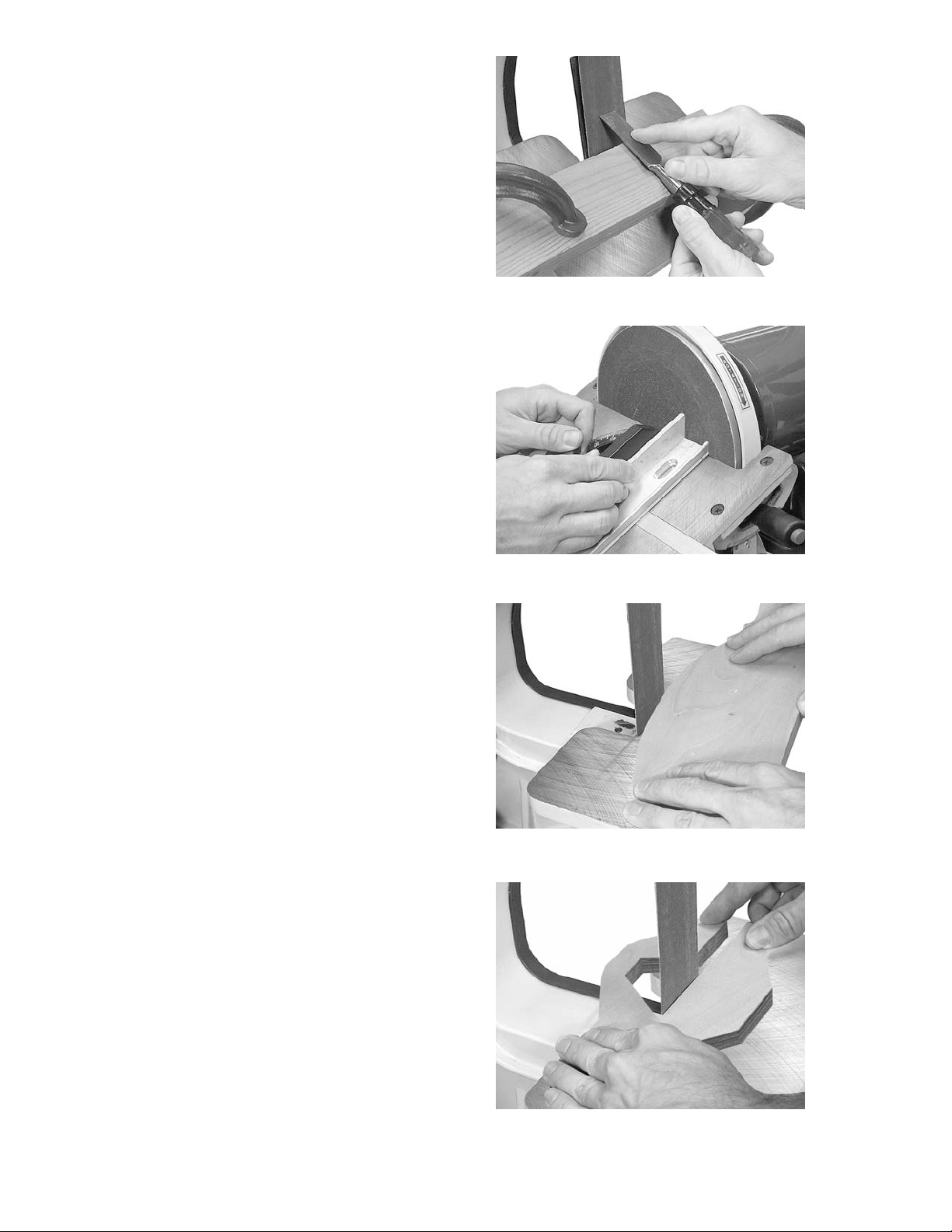
Sander.
• Sharpening a wood chisel on the sanding
belt using a block of wood. Use t he block of
wood to support the chisel and provide
clearance for the chise l handle. See Figure
18. Sand a bevel in the block of wood in
order to position the block as close as
possible to the sanding belt and clamp the
block to the table.
• A cold chisel can also be sharpened on the
belt table with the table tilted.
• Sanding aluminum on the disc unit with the
table tilted and using the miter gauge as a
guide. See Figure 19.
Figure 18
• Sanding outsid e curves on the be lt unit with
the platen removed. See Figure 20.
• Polishing using a felt belt (not provided) in
place of the sanding belt.
Note: Most polishing operations are
performed with the platen removed.
• Sanding in tight areas with the sandi ng belt.
See Figure 21.
Figure 19
Figure 20
17
Figure 21

Maintenance
Before performing any
maintenance on the machine, disconnect it
from the electrical supply by pulling out the
plug or switching off the main switch.
Failure to comply may cause serious injury.
Keep the table surfaces clean and f ree of rus t. If
rust appears on th e tables, use 000 steel wool
with a paste m ixture of hou sehold amm onia and
good commercial detergent (or use a
commercial rust remover available from most
hardware stores.)
A light coat of paste wax o n the tables will help
protect them from tarnish and reduce friction
between table and workpiece.
Note: Do not get paste wax on the abras ive be lt
or disc.
Check all fasteners for tightness.
Inspect the power cord ; if worn, cut, or d am aged
in any way, have it replaced immediately.
Inspect the abrasive belt and disc. If either is
worn, replace it.
Occasionally remove the belt cover and brush
out any shavings or debris from around the
wheels.
Lubrication
All of the ball bearings are packed with grease
and sealed at the factory. They require no
further lubrication.
Replacement Parts
Replacement parts are lis ted on the fol lowing pag es. To order parts or reach our service de partm ent, call
1-800-274-6848 Monday through Friday, 8:00 a.m. to 5:00 p.m. CST. Having the Model Number and
Serial Number of your machine available when you call will allow us to serve you quickly and accurately.
Non-proprietary parts , such as fas teners, can be foun d at local hard ware stores, or may be ordered f rom
JET. Some parts are shown for reference only, and may not be available individually.
18

Troubleshooting
Trouble Probable Cause Remedy
Not connected to power source. Connect to power source.
Determine reason for blown fuse/
Branch circuit fuse is blown or the
circuit breaker is tripped.
Sander will not start.
tripped breaker (such as short circuit
or motor overload). Correct reason for
fault. Replace fuse/ reset circuit
breaker.
Voltage is too low.
Switch is defective. Replace switch.
Motor failure. Replace motor.
Motor stalls easily. Low voltage.
Abrasive disc
separates from
aluminum disc.
Abrasive belt will not
track correctly.
Improper bond.
Belt not centered on wheels. Readjust tracking. See page 14.
Belt stretched unevenly. Replace abrasive belt.
Belt is jointed improperly.
Wheel is worn. Replace affected wheel.
Worn bearings.
Check power source for proper
voltage.
Check power source for proper
voltage and correct if necessary.
Clean residual adhesive from
aluminum disc, and re-apply
adhesive-backed abrasive disc.
Check the belt for an irregular seam
or shape. Replace if needed.
Check all the bearings for excessive
heat or loose shafts. Replace if
necessary.
Abrasive belt slips or
stalls when pressure
is applied.
Frequent
replacement of
abrasive belt or disc.
Abrasive belt tension inadequate;
spring in tension mechanism is worn.
Excessive pressure being applied to
platen.
Too much pressure being applied to
workpiece.
Full width of belt or disc not being
used.
Incorrect abrasive material or grit
size.
19
Replace spring.
Reduce pressure on abrasive belt
(and platen).
Allow the belt to do the cutting.
Excessive pressure only dulls the grit
and removes it from the cloth.
Stroke across abrasive belt using full
width of belt surface.
Check with your abrasives supplier for
recommendations on the type and
coarseness of the abrasive required
for your particular workpieces .

Assembly Drawing
20

Parts List
Index No. Part No. Description Size Qty
1 ............... J-41002-01G ............ Base ..................................................................... ........ ............................ 1
2 ............... TS-0680042 ............. Flat Washer .......................................................... 3/8” .............................. 2
3 ............... TS-1551031 ............. Lock Washer ........................................................ M5 ............ ................... 4
4 ............... TS-1515041 ............. Socket Head Cap Screw ...................................... M8x30 ......................... 4
5 ............... TS-0050021 ............. Hex Cap Screw .................................................... 1/4-20x5/8” .................. 4
6 ............... TS-0720081 ............. Lock Washer ........................................................ 5/16” ............................ 4
7 ............... 41002-07 .................. Rubber Foot ......................................................... .................................... 4
8 ............... TS-0680021 ............. Flat Washer .......................................................... 1/4” .............................. 4
9 ............... TS-0570011 ............. Hex Nut ................................................................ 1/4”-20......................... 4
10 ............. TS-1525021 ............. Socket Set Screw ................................................. M10x12 ....................... 1
11 ............. 41002-11 .................. Capacitor Cap ...................................................... .................................... 1
12 ............. 41002-12A ............... Capacitor .............................................................. 30uF, 300V ................. 1
13 ............. HBS814GH-166-5 .... Cross Head Flat Screw ........................................ 10-24x3/8” ................... 6
14 ............. 41002-14 .................. Capacitor Clamp ................................................. .................................... 1
15 ............. TS-0570011 ............. Hex Nut ................................................................ 1/4”-20......................... 4
16 ............. TS-0720071 ............. Lock Washer ........................................................ 1/4” .............................. 4
17 ............. TS-1504051 ............. Socket Head Cap Screw ...................................... M8x25 ......................... 4
18 ............. 41002-18 .................. Strain Relief Plate ................................................ .................................... 1
19 ............. 41002-19 .................. Strain Relief.......................................................... 6N-4 ............................ 1
20 ............. 41002-20 .................. Line Cord .............................................................. .................................... 1
22 ............. 41002-22 .................. Strain Relief Bushing ........................................... .................................... 1
23 ............. 41002-23 .................. Self Tapping Screw .............................................. 10-24X3/8” .................. 2
24 ............. J-41002-24G ............ Motor Housing Base ............................................ .................................... 1
24A ........... J-41002-24A1G ........ Motor Assembly ................................................... 115V, 1Ph ................... 1
25 ............. 41002-25 .................. Switch with Key .................................................... .................................... 1
26 ............. 41002-26 .................. Copper Washer .................................................... .................................... 1
27 ............. TS-081C022 ............. Phillips Pan Head Machine Screw ....................... 10-24x3/8” ................... 1
28 ............. TS-1540031 ............. Hex Nut ................................................................ M5 ............................... 4
29 ............. J-41002-29G ............ End Shield ............................................................ .................................... 2
30 ............. BB-6203ZZ ............... Bearing ................................................................. 6203ZZ........................ 2
31 ............. 41002-31 .................. Motor Fan ............................................................. .................................... 1
32 ............. 41002-32 .................. Armature .............................................................. .................................... 1
33 ............. 41002-33 .................. Stator .................................................................... .................................... 1
34 ............. 41002-34 .................. Pan Head Screw .................................................. 1/4-20x7/8” .................. 4
35 ............. J-41002-35G ............ Motor Housing ...................................................... ............... ..................... 1
36 ............. 41002-36 .................. Pan Head Screw .................................................. M5x0.8x163 ................ 4
37 ............. 41002-37 .................. Bar ........................................................................ .................................... 1
38 ............. 41002-38 .................. Pointer .................................................................. .................................... 1
39 ............. HBS814GH-200 ....... Phillips Pan Head Machine Screw ....................... 1/4x3/8” ....................... 1
40 ............. 41002-40 .................. Miter Body ............................................................ .................................... 1
41 ............. 41002-41 .................. Knob ..................................................................... .................................... 1
42 ............. TS-2361081 ............. Lock Washer ........................................................ M8 ............................... 2
43 ............. 41002-43 .................. Miter Gauge Assembly (includes index 37 thru 41, 99, 100) .................... 1
44 ............. TS-1534052 ............. Phillips Pan Head Machine Screw ....................... M6x15 ......................... 4
45 ............. J-41002-45G ............ Disc Table ............................................................ .................................... 1
46 ............. 41002-46 .................. Armature Guard ................................................... .................................... 1
47 ............. 41002-47 .................. Handle .................................................................. .................................... 3
48 ............. J-41002-48G ............ Right Trunnion ..................................................... .................................... 1
49 ............. J-41002-49G ............ Disc Guard ........................................................... .................................... 1
50 ............. TS-1540061 ............. Hex Nut ................................................................ M8 ............................... 4
51 ............. 41002-51 .................. Aluminum Disc ..................................................... 8" ................................. 1
52 ............. 6291479 ................... Key ....................................................................... 5x5x30mm .................. 1
53 ............. 5640211 ................... Abrasive Disc, 100 grit ......................................... 8” ................................. 1
54 ............. 41002-54 .................. Dust Chute. .......................................................... .................................... 1
55 ............. J-41002-55G ............ Left Trunnion ........................................................ .................................... 1
56 ............. TS-1523011 ............. Socket Set Screw ................................................. M6x6 ............. .............. 1
21

Parts List
57 ............. TS-1505021 ............. Socket Head Cap Screw ...................................... M10x20 ....................... 2
58 ............. J-41002-58G ............ Belt Housing ......................................................... ............. ....................... 1
59 ............. TS-0680031 ............. Flat Washer .......................................................... 5/16” ............................ 4
60 ............. TS-0570011 ............. Hex Nut ................................................................ 1/4”-20......................... 1
61 ............. TS-1490021 ............. Hex Cap Screw ................................................... M8x16 ......................... 2
62 ............. TS-0680031 ............. Flat Washer .......................................................... 5/16” ............................ 3
63 ............. 41002-63 .................. Belt Table Bracket ................................................ .................................... 1
64 ............. J-41002-64G ............ Belt Table ............................................................. .................................... 1
65 ............. TS-1524031 ............. Socket Set Screw ................................................. M8x12 ............ ............. 1
66 ............. 41002-66 .................. Shaft ..................................................................... .................................... 1
67 ............. BB-6202ZZ ............... Bearing ................................................................. 6202ZZ........................ 4
68 ............. 41002-68 .................. Idler Wheel ........................................................... .................................... 2
69 ............. 5640491 ................... Retaining Ring ..................................................... S-15 ............................ 2
70 ............. 41002-70 .................. Abrasive Belt ........................................................ 100 Grit 2”x42” ............ 1
71 ............. 41002-71 .................. Stand Off .............................................................. .................................... 2
72 ............. 41002-72 .................. Drive Wheel.......................................................... .................................... 1
73 ............. TS-1523031 ............. Socket Set Screw ................................................. M6x10 ............ ............. 1
74 ............. 41002-74 .................. Belt Cover ............................................................ .................................... 1
75 ............. 41002-75 .................. Knob ..................................................................... .................................... 2
76 ............. 41002-76 .................. Tracking Wheel Cam Shaft .................................. .................................... 1
77 ............. 5513018 ................... Retaining Ring ..................................................... S-17 ............................ 1
78 ............. 41002-78 .................. Tension Spring ..................................................... .................................... 1
79 ............. 41002-79 .................. Spring Cap ........................................................... .................................... 1
80 ............. 41002-80 .................. Handle with Knob ................................................. .................................... 1
81 ............. 41002-81 .................. Tracking Bracket .................................................. .................................... 1
82 ............. TS-1540041 ............. Hex Nut ................................................................ M6 ............................... 1
83 ............. TS-1503051 ............. Socket Head Cap Screw ...................................... M6x20 ......................... 1
84 ............. 41002-84 .................. Spring Plate.......................................................... .................................... 2
85 ............. TS-1502021 ............. Socket Head Cap Screw ...................................... M5x10 ......................... 2
86 ............. TS-1502031 ............. Socket Head Cap Screw ...................................... M5x12 ......................... 2
87 ............. 41002-87 .................. Belt Platen ............................................................ .................................... 1
88 ............. TS-1504031 ............. Socket Head Cap Screw ...................................... M8x16 ......................... 1
89 ............. TS-152707 ............... Hex Wrench ......................................................... M6 ............................... 1
90 ............. TS-152705 ............... Hex Wrench ......................................................... M4 ............................... 1
91 ............. TS-152704 ............... Hex Wrench ......................................................... 3mmx140L ...... ............ 1
92 ............. TS-0680031 ............. Flat Washer .......................................................... 5/16” ............................ 4
93 ............. 41002-93 .................. Pan Head Screw .................................................. 10-24x1/4” ................... 3
94 ............. 41002-94 .................. Serrated Washer ................................................. M5 ............................... 1
95 ............. 41002-95 .................. Cable .................................................................... 18# 100m/m ................ 1
96 ............. 41002-96 .................. Terminal ............................................................... A-3 .............................. 1
97 ............. 41002-97 .................. Cable .................................................................... 22# 200m/m ................ 1
98 ............. TS-0267041 ............. Socket Set Screw ................................................. 1/4-20x3/8” .................. 1
99 ............. TS-1550031 ............. Flat Washer .......................................................... M5 ............................... 1
100 ........... TS-0680022 ............. Flat Washer .......................................................... 1/4” .............................. 1
101 ........... 41002-101 ................ Indicator ............................................................... .................................... 1
102 ........... 41002-93 .................. Pan Head Screw .................................................. 10-24x1/4” ................... 1
22

Notes
23

427 New Sanford Road
LaVergne, Tennessee 37086
Ph.: 800-274-6848
www.jettools.com
24
 Loading...