


Operating Instructions and Parts Manual
Belt and Disc Sander
Model J-41002
–
2" x 42" Belt and 8" Disc Sander
WALTER MEIER (Manuf acturing) Inc.
427 New Sanford Road
LaVergne, Tennessee 37086 Part No. M- 577004
Ph.: 800-274-6848 Revision B 05/2011
www.walt er meier.c om Copyright © 2011 Walt er Meier (M anufacturi ng) Inc.

W arranty and Service
Walter Meier (Manufacturing) Inc., warrants every product it sells. If one of our tools needs service or repair, one of
our Authorized Service Centers located throughout the United States can give you quick service. In most cases, any
of these Walter Meier Authorized Service Centers can authorize warranty repair, assist you in obtaining parts, or
®
perform routine maintenance and major repair on your JET
your area call 1-800-274-6848.
MORE INFORMATION
Walter Meier is consistently adding new products to the line. For complete, up-to-date product information, check with
your local Walter Meier distributor, or visit waltermeier.com.
WARRANTY
JET products carry a limited warranty which varies in duratio n based upon the product (MW = Metalworking, WW =
Woodworking).
WHAT IS COVERED?
This warranty covers any defects in workmanship or materials subject to the e xceptions stated below. Cutting tools,
abrasives and other consumables are excluded from warranty coverage.
WHO IS COVERED?
This warranty covers only the initial purchaser of the product.
WHAT IS THE PERIOD OF COVERAGE?
The general JET warranty lasts for the time period specified in the product literature of each product.
WHAT IS NOT COVERED?
Five Year Warranties do not cover woodworking (WW) products used for commercial, industrial or educational
purposes. Woodworking products with Five Year Warranties that are used for commercial, industrial or education
purposes revert to a One Year Warranty. This warranty does not cover defects due directly or indirectly to misuse,
abuse, negligence or accidents, normal wear-and-tear, improper repair or alterations, or lack of maintenance.
HOW TO GET SERVICE
The product or part must be returned for examination, postage prepaid, to a location designated by us. For the name
of the location nearest you, please call 1-800-274-6848.
You must provide proof of initial purchase date and an explanation of the complaint must accompany the
merchandise. If our inspection discloses a defect, we will repair or replace the product, or refund the purchase price,
at our option. We will return the repaired product or replacement at our expense unless it is determined by us that
there is no defect, or that the defect resulted from causes not within the scope of our warranty in which case we will,
at your direction, dispose of or return the product. In the event you choose to have the product returned, you will be
responsible for the shipping and handling costs of the return.
HOW STATE LAW APPLIES
This warranty gives you specific legal rights; you may also have other rights which vary from state to state.
LIMITATIONS ON THIS WARRANTY
WALTER MEIER (MANUFACTURING) INC., LIMITS ALL IMPLIED WARRANTIES TO THE PERIOD OF THE
LIMITED WARRANTY FOR EACH PRODUCT. EXCEPT AS STATED HEREIN, ANY IMPLIED WARRANTIES OR
MERCHANTABILITY AND FITNESS ARE EXCLUDED. SOME ST ATES DO NOT ALLOW LIMITATIONS ON HOW
LONG THE IMPLIED WARRANTY LASTS, SO THE ABOVE LIMITATION MAY NOT APPLY TO YOU.
WALTER MEIER SHALL IN NO EVENT BE LIABLE FOR DEATH, INJURIES TO PERSONS OR PROPERTY, OR
FOR INCIDENTAL, CONTINGENT, SPECIAL, OR CONSEQUENTIAL DAMAGES ARISING FROM THE USE OF
OUR PRODUCTS. SOME STATES DO NOT ALLOW THE EXCLUSION OR LIMITATION OF INCIDENTAL OR
CONSEQUENTIAL DAMAGES, SO THE ABOVE LIMITATION OR EXCLUSION MAY NOT APPLY TO YOU.
Walter Meier sells through distributors only. The specifications in Walter Meier catalogs are given as general
information and are not binding. Members of Walter Meier reserve the right to effect at any time, without prior notice,
those alterations to parts, fittings, and accessory equipment which they may deem necessary for any reason
®
whatsoever. JET
branded products are not sold in Canada by Walter Meier.
tools. For the name of an Authorized Service Center in
2

Table of Contents
Warranty and Ser vice..........................................................................................................................2
Table of Contents ...............................................................................................................................3
Warn in g .............................................................................................................................................4
In trodu ction ........................................................................................................................................6
Spe cifi cation s .....................................................................................................................................6
Features and Terminology ...................................................................................................................7
Unpacking ..........................................................................................................................................8
Contents of the Shipping Container ..................................................................................................8
Ass embly ...........................................................................................................................................9
Installing Belt Table .........................................................................................................................9
Installing Dust Chute .......................................................................................................................9
Installing Disc Table ...................................................................................................................... 10
Installing Miter Gauge .................................................................................................................... 10
Installing Tension Handle ............................................................................................................... 10
Grounding I nstructions ...................................................................................................................... 11
115 Volt Operat ion ........................................................................................................................ 11
Adju s tmen ts ..................................................................................................................................... 12
Tilting the Belt Table ...................................................................................................................... 12
Tilting the Disc Table ..................................................................................................................... 12
Use of the Miter Gauge .................................................................................................................. 13
Belt Platen .................................................................................................................................... 13
Abrasive Belt Replacement ............................................................................................................ 14
Tracking the Abrasive Belt ............................................................................................................. 14
Abrasive Disc Replacement ........................................................................................................... 15
Aluminum Disc Removal ................................................................................................................ 15
Operation ......................................................................................................................................... 16
Start ing and Stopping the Sander ................................................................................................... 16
Belt and Disc Movement ................................................................................................................ 16
Typical Operations ........................................................................................................................ 16
Extension Cords ............................................................................................................................ 11
Mai nten ance .................................................................................................................................... 18
Replacement Parts ........................................................................................................................... 18
Troubleshooting ................................................................................................................................ 19
Assembly Drawing......................................................................................................................... 20
Parts List ...................................................................................................................................... 21
3

Warning
1. Read and understand t he entire owner’s manual befor e attempting assembly or operation.
2. Read and understand the war nings post ed on the machine and in this manual. Fa ilure t o comply with
all of these warnings may cause serio us injury.
3. Replace the warning labels if they become obscured or removed.
4. This sander is designed and intended f or use by properly tr ained and experienced perso nnel only. If
you are not fami liar wit h the proper and saf e operat ion of a sa nder, do not use until proper t raini ng
and knowledge have been obtained.
5. Do not use this sander for other t han its intended use. If used for other purposes, Walter Meier
(Manufacturing) Inc., disclaims any real or implied w arranty and holds itself harmless f rom any injury
that may result from that use.
6. Always wear appr oved safet y glasses/ face shields while usi ng this sa nder . Everyday eyeglasses only
have impact resistant lenses; t hey are not safety glasses.
7. Before operati ng this sander, remove tie, r ings, w atches and other jewelry, a nd roll sleeves up past
the elbows. Remove a ll loose clothing and confine long hair. Non-slip footw ear or anti-skid floor strips
are recommended. Do not w ear gloves.
8. Wear ear pr otect or s (plugs or muff s) during extended periods of operation.
9. Some dust created by power sanding, sawing, grinding, drilling and other construction activities
contain chemicals k nown to the State of California to c ause cancer, bir t h defects or other reproductive
harm. Some examples of these chemicals are:
• Lead from lead based paint.
• Crystalline silica from bricks, cement and ot her masonry products.
• Arsenic and chromium fr om chemically treated lumber.
Your risk of exposure varies, depending on how often you do this type of work. To reduce your
exposure to these chemicals, work in a well-ventilated area and work with approved safety
equipment, such as face or dust masks that are specifically designed to filter out microscopic
particles.
10. Do not operate this machine while tired or under the influence of drugs, alcohol or any medicat io n.
11. Make cer t ain the switch is in the OFF position before co nnecti ng the machine to the power supply.
12. Make cer t ain the machine is properly grounded.
13. Make all machine adjustme nts or maintenance with the machine unplugged from the power source.
14. Remove adjusting keys and wrenches. Form a habit of checking to see that keys and adjusting
wrenches are removed from the mac hine before tur ning it on.
15. Keep safety guards in place at all times when the machine is in use. If removed for maintenance
purposes, use extreme cautio n and replace t he guards immed iately.
16. If there is a tende ncy for the machi ne to t ip over or move d uring oper ation, such as when sandi ng
long or heavy boards, the machine must be securely f ast ened to a supporti ng surface.
17. Check damaged parts. Before further use of the machine, a guard or ot her part that is damaged
should be carefully checked to determine that it will operate properly and perform its intended
function. Check for alignme nt of moving part s, binding of moving part s, break age of part s, mounting
and any other condit ions t hat may affect its oper ation. A guard or other part that is damaged s hould
be properly repaired or r eplaced.
18. Provide for adequate space surrounding work area and non-glare, overhead lighti ng.
19. Keep the floor around t he machine clean and free of sc r ap material, oil and grease.
20. Keep visitors a saf e dist ance from the wor k ar ea. Keep children away.
4

21. Make your workshop child proof with padlocks, master switches or by removing star t er keys.
22. Give your work undivided att ention. Looking aro und, carrying on a conversat ion and “ horse-play” are
careless acts that can result in serio us injury.
23. Maintain a balanced s tance at all times so t hat you do not fall or lea n against the abrasives or other
moving parts. Do not overreac h or use excessive for c e t o perfor m any machine operation.
24. Use the right tool at t he correc t speed and feed rate. Do not force a tool or at t achment to do a jo b f or
which it was not designed. The r ight t o ol will do t he job b e tter a nd sa fer.
25. Make sure the abrasive belt is running in the proper direction. When disc sanding, place the
workpiece agai nst t he downward rotating part of the abrasive disc.
26. This machine can be used for sandi ng wood or meta l products. However, combini ng wood dust a nd
metal filings can create a f ire hazard. Make s ure yo ur d ust col lect or is free of w ood dust deposits
before pr ocess ing metal products.
27. Use recommended accessor ies; improper acc essor ies may be ha zardo us.
28. Maintain tools with care. Follow instructions for lubricating the mac hine a nd changing accessori es.
29. Abrasi ve discs must be stored in a controlled environment. Relative humidity should be 35% to 50%
and the temperature should be between 60° and 80° Fahrenheit. Failure to do this could cause
premature disc failure.
30. Exami ne t he face of the abrasi ve disc or belt caref ully. Excessive sandi ng t hat w ears down to t he
backing material can tear the disc/belt. Never use an abrasive which s hows backing, nicks or c uts on
the surface or edge, or damage due to creasing or poor handling.
31. Turn off t he mac hine bef or e cleaning. Use a brush or compressed air t o r emo ve chips or debr is — do
not use your hand s.
32. Never lea ve the machine r unni ng unattended. Turn the power off and do not leave the machine until it
comes to a complete stop.
33. Do not use the sander in wet or damp locations.
34. Remove loose items a nd unnecessary w or k pieces f r om the area befor e starting the machine.
Familiarize yours elf with the f ollow ing saf et y not ices used in t his manual:
This means that if precautions are not heeded, it may result i n minor injury and/or
possible machine damage.
This means that if precautions are not heeded, it may result i n serio us injury or possibly
even death.
- - SAVE THESE I NSTRUCTI ONS - -
5

Introduction
This manual is provided by Walter Meier (Manufacturing) Inc., covering the safe operation and
maintenance pr ocedures for a JET 2x42x8 Belt and Disc Sa nder. This manual contai ns instr uct io ns o n
installation, safety precautions, general operating procedures, maintenance instructions and parts
breakdown. T his mac hine has been designed and constructed to provide years of tr ouble fr ee oper ation if
used in accor dance with i nstr uctio ns set forth i n t his ma nual. I f there are any questio ns or co mments,
please contact eit her your local supplier or Walter Meier. Walter Meier can also be reached at our web
site: www.waltermeier.com.
Specifications
Model Number ..........................................................................................................................J-41002
Stock Number .......................................................................................................................... 577004
Belt Size (in.)(LxW) ......................................................................................................................42 x 2
Disc Size (in.) ....................................................................................................................... 8 diam eter
Motor ........................................................................................................................ 3/4HP, 1Ph, 115V
Belt Table Size (in.)(LxW).............................................................................................................10 x 6
Disc Table Size (in.)(LxW) ................................................................................................ 10-3/4 x 7-1/2
Table Tilt (deg. ) ......................................................................................................................... 0 to 45
Dust Chutes (in.)................................................................................................... two @ 1-1/2 diameter
Overall Size (in.)(WxDxH) ....................................................................................... 20-1/2 x 22-3/4 x 20
Approximate Net Weight (lbs.) ........................................................................................................... 58
Approximate Shipping Weight (lbs.) ................................................................................................... 64
The above specificati ons were current at the time t his manual w as publis hed, but beca use of our policy of
continuo us impro vement, Walt er M eier r eser ves the right to change s pecificat ions at any time and without
prior notice, without incurring obligations.
6

Features a nd Terminology
7

Unpacking
Open shipping co ntainer a nd check for s hipping
damage. Report any damage immediately to
your distributor and shipping agent. Do not
discard a ny shipping materia l until the sa nder is
assembled a nd running properly.
Compare the contents of your co ntainer w ith the
following parts list to make sure all parts are
intact. Missing par ts, if any, s hould be reported
to your dist ributor. Read the instruction ma nual
thoroughly for assembly, maintenance and
safety instructions.
Contents of the Shipping Container
1 Belt and Disc Sander
1 Belt Table
1 Disc Table with trunnions
1 Miter Gauge
1 Dust Chute
6 Phillips Pan Hd. Machine Screws, 3/ 16x3/8”
3 Handles
3 Flat Washers, 3/ 8”
1 Tension Handle
1 Hex Nut, 1/4”
3 Hex Wrenches, 3, 4 and 6mm
1 Owner's Manual
1 Warranty Card
Read and underst and the entire contents of this manual before at t empting set-up
or operation! Failure to comply may cause ser iou s inj ur y.
8

Assembly
Tools needed for assemb ly:
• 10mm ope n-e nd wr ench
• Cross- poi nt (Phillips) scr ewdriver
• Combination square, or similar angle
measuring device.
Sander must be unplugged
from power source duri ng assembly.
Remove the protect i ve coati ng from t he surfaces
of the sander and from any loose parts. This
coating may be removed with a soft cloth
moistened with kerosene (do not use acetone,
gasoline or lacquer thinner for this purpose).
After cleaning, cover the table surfaces with a
good quality paste w ax.
Leave enough space aro und the sander for long
workpieces and for general mai nte nance.
If needed, the s ander can be bo lted t o a t able or
workbench using the holes in the base. If the
sander has a tendency to walk or slide during
operation, it must be bolted to a supporting
surface.
Installing Belt Table
1. Unscrew t he stud. See Figure 1.
2. Position the bracket of the belt table over the
holes in the casti ng as shown, and re- insta ll
the stud into its hole.
3. Place a flat washer onto a handle, and i nsert
the handle through the table bracket and
into the hole. Scr ew the handle a ll the way
into the hole.
NOTE: The handle is spring loaded; screw
the handle in by rotating clockwise, then pull
outward on the handle. Rotate the handle
back to position, then release it, making s ure
it seats itself upon the pin. Continue the
process until the handle is tightened in the
hole.
Installing Dust Chute
The sander has two 1- 1/ 2” diameter dust chutes.
The dust chute for the belt is located on the belt
cover. The dust chute for the disc should be
installed as s how n in Figure 2, usi ng the si x (6)
pan head machine screw s that are pr ovided.
Figure 1
The dust chutes ca n be co nnected to a vac uum
system to collect dust particles.
Figure 2
9
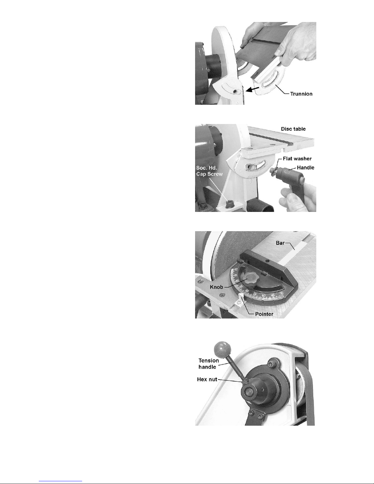
Installing Disc Table
1. Position t he disc table at an angle, as show n
in Figure 3, and slide t he table on so that the
trunnion slots fit over the raised tracks on
the disc guard.
2. Install a flat washer onto each of the two
remaining handles. Insert the handle into the
holes through the left and right trunnions.
See Figure 4.
3. The gap between t he sandi ng disc and the
disc table s hould be a ma ximum of 1/16” . If
it is larger than this, loosen the two socket
head cap screw s on the disc g uard (o ne is
shown i n Figure 4) and slide the disc guard
to achieve this gap measureme nt.
4. When fi nished, tighten the tw o socket head
cap screws securely.
Figure 3
Figure 4
Insta lling Miter Gau ge
Insert the miter gauge bar into one end of the
miter slot in the disc table. See Figure 5.
The miter ga uge ca n be used in either directio n
in the slot to achieve the most effective
positioning of the workpiece against the abrasive
disc.
Installing Tension Handle
1. Place the 1/4” hex nut onto t he threads of
t he t ension handle .
2. Screw the tension hand le into the hole o n
the hub, t hen ti ghte n the hex nut against the
hub. See Figure 6.
Figure 5
Figure 6
10

Grounding Instr uctions
This machine must be
grounded whi le in use to prot ect t he oper at or
from electric shock.
In the event of a malfunction or breakdown,
grounding pro vides a path of least r esist ance for
electric current to reduce the risk of electric
shock. This tool is eq uipped w ith an electric cor d
having an equipment-grounding conductor and a
grounding plug. The pl ug m ust be i nserted into a
matching receptacle that is properly installed
and gro unded i n ac cor dance with al l local codes
and ordinances.
Do not modify t he plug pro vided. I f it will not fit
the outlet, ha ve t he pr oper outlet insta lled by a
qualified ele c trician.
Improper connection of the equipmentgrounding conductor can result in a risk of
electric shock. The conductor, with insulation
having an outer surface that is green with or
without yellow stripes, is the equipmentgrounding conduc tor. If r epair or replaceme nt of
the electric cord or plug is necessary, do not
connect t he equipment-gr ounding conductor t o a
live terminal.
Check with a qualified electrician or service
personnel if the grounding instructions are not
completely understood, or if in doubt as to
whether the t ool is proper ly gr ounded. Use only
three wire exte nsion cor ds t hat have three-prong
grounding pl ugs and t hree-pole receptac les that
accept t he tool’s plug.
115 Volt Operation
As received from the factory, your sander is
ready to r un at 115 volt oper at ion. This sander is
intended for use on a circuit that has an outlet
and a plug t hat looks like the one illustrated in
Figure 7.
A temporary adapt er, like the adapt er in Figure
8, may be used to connect this plug to a twopole receptacle, as shown in Figure 8, if a
properly grounded outlet is not available. The
temporary adapter should only be used until a
properly gro unded outlet can be installed by a
qualified electrician. This adapter is not
applicable in Canada. The gree n co lored rigid
ear, lug, or tab, extending from the adapter,
must be connected to a permane nt ground such
as a properly grounded outlet bo x, as show n in
Figure 8.
Figure 8
Extension Cords
Use proper e xtensio n cor ds . M ake sure the cord
rating is suitable for the amperage of the
machine’s motor . An undersized cord w ill cause
a drop in li ne voltage res ulting in loss of power
and overheating.
Use the chart in Figure 9 as a ge neral guide i n
choos ing t he correct si ze cord. T he smaller the
gauge number, the heavier the cord.
Recommended Gauges (AWG) of Extension Cords
Extension Cord Length *
25
50
75
100
150
200
Amps
< 5 16 16 16 14 12 12
5 to 8 16 16 14 12 10 NR
feet
feet
feet
feet
feet
feet
Figure 7
8 to 12 14 14 12 10 NR NR
12 to 15 12 12 10 10 NR NR
15 to 20 10 10 10 NR NR NR
21 to 30 10 NR NR NR NR NR
*based on limit in g the line voltage drop to 5V at 150% of the
rated am per es.
NR: Not Recomme nded.
Figure 9
11

Adjustments
Tilting the Belt Table
The belt table ti lt s f rom zero (horizontal) down to
45°.
1. Loosen the ha ndle and adj ust t he table i nto
desired position.
2. Check the angle with a machinist’s
protractor or similar measuring device that
has the required angle. Figure 10 shows a
square being used to confirm the zero, or
horizontal, posit ion. Place the sq uare flat on
the table a nd against t he belt. Push agai nst
the belt until the square is against the
platen.
3. Make any ad justments t o the table a ngle as
necessary until it is square with the belt.
4. Tighten the handle secure ly.
To avoid trapping the
workpiece or fingers between the table and
abrasive belt, the table edge should be
positioned a maximum of 1/16” from the
abrasive belt.
Tilting the Disc Table
The disc table tilts f r om zero (horizonta l) down to
45°.
1. Loosen both handles and adjust the table
until the indicator lines up with the desired
angle on the scale. It is a good idea to
confirm this angle using your angle
measuring de vice placed f lat upon t he table
and against the abrasive disc.
2. Figure 11 shows a square being used to
confirm the zero, or horizontal pos ition of the
disc table.
3. Make any necessary adjustments to the
table angle. If the table is square with the
disc but the angle indicator needs slight
adjustment, loosen the screw on the
indicator and shift the indicator as needed.
Re-tighten t he screw .
4. Ti ghten bot h handle s secur ely .
To avoid trapping the
workpiece or fingers between the table and
abrasive disc, the table edge should be
positioned a maximum of 1/16” from the
abrasive disc.
Figure 10
Figure 11
12

Use of t he Miter G auge
The miter gauge is used to sand accurate
angles on workpieces. When using the miter
gauge on t he hor izontal table positio n, yo u can
sand a single angle. By tilti ng the disc table and
using the miter gauge in combination with the
table tilted, it is possible to sand compound
angles as well.
The miter gauge rotates to 30° for bevel
sanding. Loose n t he knob and r otat e the ga uge
body until the pointer lines up with the desired
angle on the scale.
Use a sq uare to co nfirm t hat the miter gauge is
set at 90° ( perpendicular to t he disc). See Fig ure
12. If slight adjustment is needed:
1. Loosen the knob.
2. Adj ust the miter gauge body unti l it is flus h
with t he squar e, and the square is flush with
the disc.
3. Tighte n the knob.
4. Loosen the screw o n t he poi nter and adj ust
the pointer until it aligns with 90° on the
scale.
5. Tighten the screw on the pointer.
Belt P l at en
The belt platen (Figure 13) is used to properly
support t he wor kpiece while sandi ng. T he platen
is constructed of heavy steel to provide
adequate support.
The platen should be adjusted so it is almost
touching the back of the abrasive belt. Loose n
the socket head cap sc r ew and adjust the platen
to the desired position. Tighten the screw to
secure the platen.
Figure 12
The platen c an be r emo ved for operatio ns s uch
as stripping, contour sa nding, polis hing or ot her
special operations. To remove the platen,
remove the socket head cap screw and washer.
Be sure to re-install the platen to perform
operations w here support of t he belt is required.
Figure 13
13
Abrasi ve Belt Rep lacemen t
1. Unplug the Sander from the power source.
2. Unscr ew and re move the two knobs on t he
belt cover.
3. Remove the belt cover.
4. Rotate the tension handle (Figure 6) to
loosen the belt, and remove the old belt fr om
around the wheels.
5. Install the new belt around the wheels.
IMPORTANT: Some sanding belts have a
directio nal arrow pr inted on the inside of t he belt.
In these cases, the belt m ust be installed so the
directio nal arrow is i n the same direct ion that the
machine is running. Refer to the rotation arrow
on top of the belt cover.
6. Install the belt cover and the two knobs.
7. Start the sander and c heck the belt track ing
before sanding operations (See “Tracking
the Abrasive Belt”).
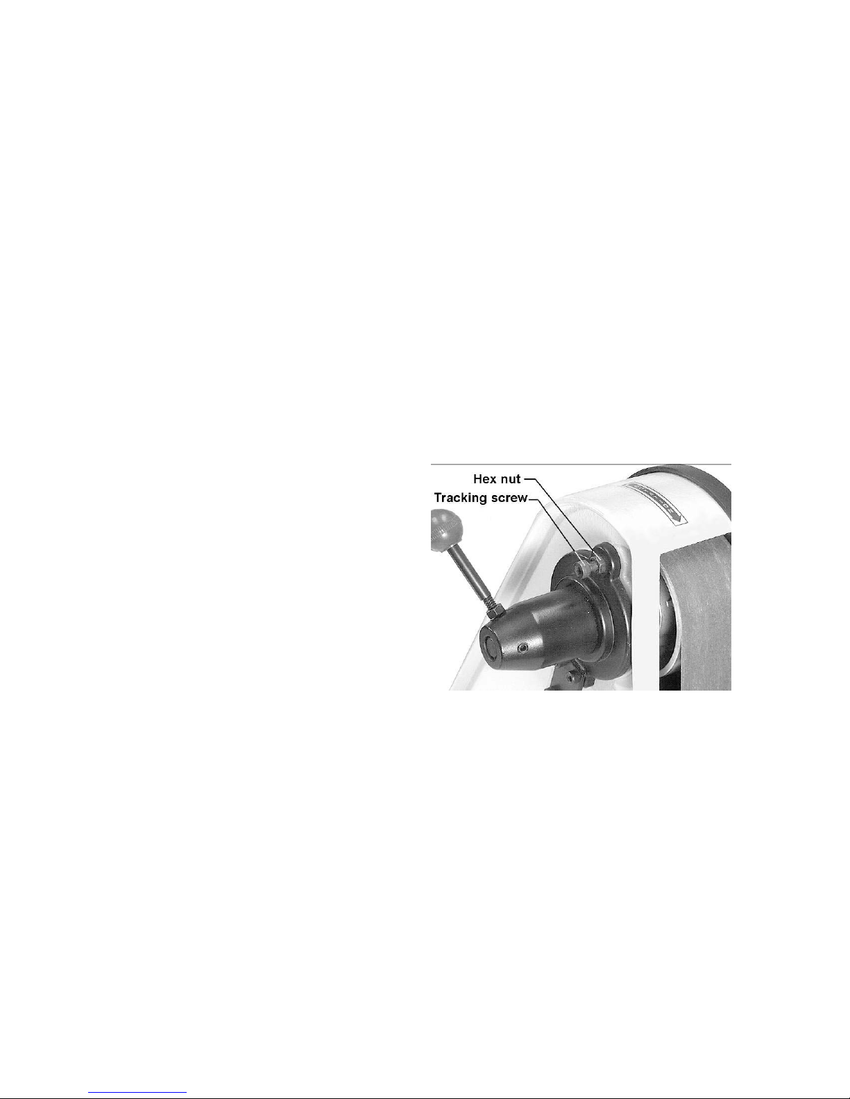
Tracki ng the Abrasive Belt
“Tracking” refers to the manner in which the
abrasive be lt is positio ned o n the wheels d uring
operation. The belt should remain in vertical
position wit hout shifti ng to o ne side or t he other
of the wheel. If any shifting occurs, the belt
needs to be tracked pr oper ly, as follows:
1. Disconnect sa nder fr om power source.
2. Remove t he side cover, and make s ure the
belt is placed e venly over t he ce nter of the
wheels. Loosen the tension and re-position
the belt if necessary. Re-install the side
cover.
3. M ove the belt by r otating the disc with yo ur
hand (do not turn on the power yet).
Observe the movement of t he belt on the top
wheel.
4. If the belt slips to one side or the other,
loosen the hex nut (Figure 14) wit h a 10mm
open-end wr ench.
5. Rotate the tracking screw (Fig ure 14) with a
5mm hex wrenc h. If t he belt is slidi ng towar d
the right, rotate the screw clockwise. If the
belt is sliding toward the left, rotate the
screw counterclockwise.
6. Continue this procedure i n small increments
until the belt is tracking properly when
moved by hand.
7. Re-connec t the sander to pow er, and cycle
the on/off switch quickly to double check the
tracking.
Figure 14
8. Re-connec t the sander to pow er, and cycle
the on/off switch quickly to double check the
tracking.
9. Make further adjustme nts as needed.
10. Tighten the hex nut to secure the setting.
14
Abrasi ve Di sc Repl acement
1. Unplug the sander fr om the power s ource.
2. Remove the dust cover and the disc table.
To remove the disc table, remove the
handles then tilt the disc table upward while
pulling it away from the disc.
3. Peel off the old abrasive disc.
4. Thoroughly clea n the al uminum d isc surface
using naptha or a similar non-flammable
solvent t hat will dry film-f ree.
5. Pull the protective backing half-way off the
new abrasive disc.
6. Carefully posit io n the new abr asive disc so it
is centered accurately on t he aluminum disc.
7. When ac curately centered, remove the rest
of the protective backing and press the
abrasive disc firmly against the aluminum
disc so complete adhesive contact is made.
8. Re-install dust cover and table.
9. Reconnect sander t o power source.
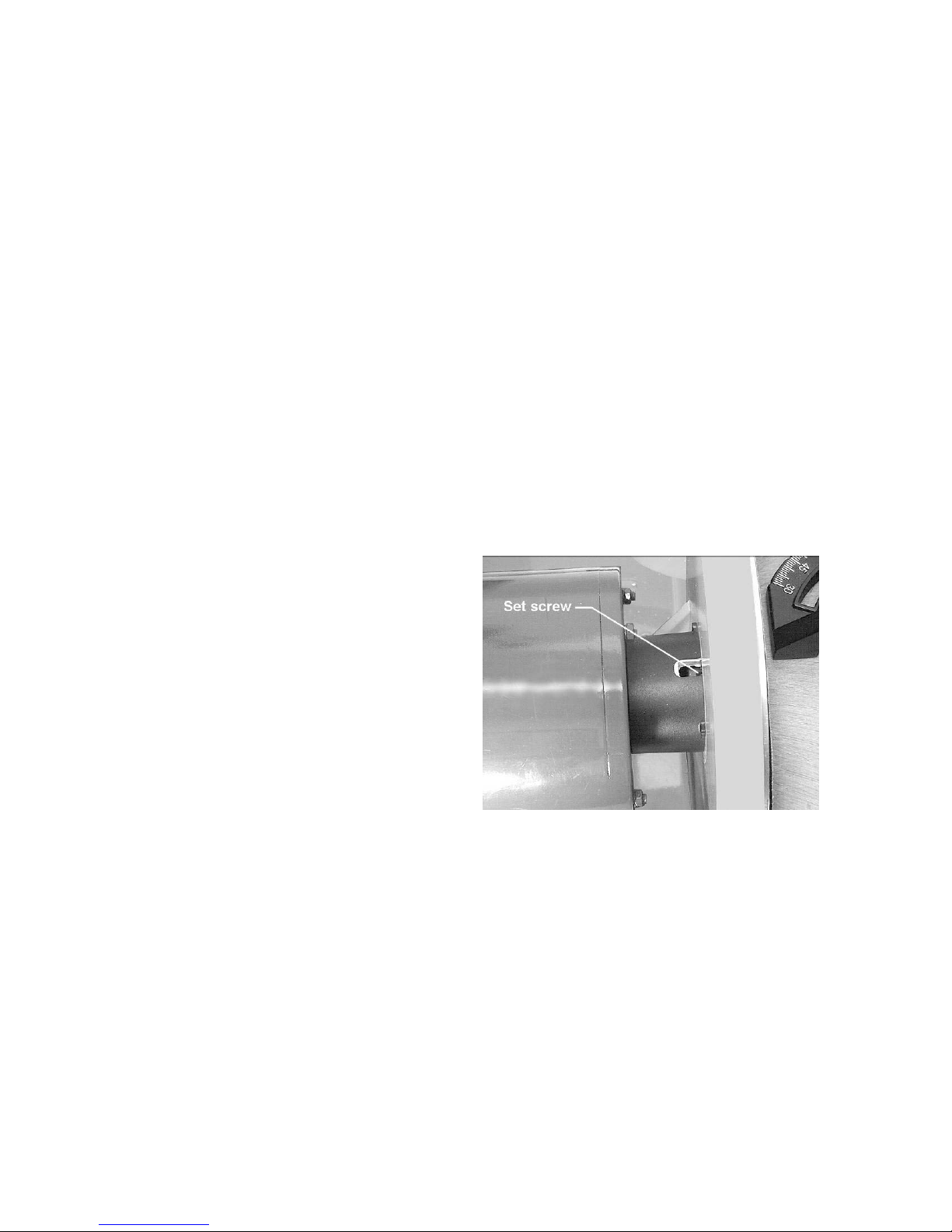
Alu mi num Disc Removal
The aluminum disc can be easily removed if
needed; for example, to facilitate cleaning the
aluminum disc when replacing abrasive discs.
1. Unplug sander from the power source.
2. Remove the disc table and the dust chute.
3. Rotate the disc until the set screw is
accessible through the opening behind the
disc guard. See F igure 15. Yo u may need to
loosen the socket head cap screws (see
Figure 4) o n the guard and shift it forwar d i n
order t o clear the set screw.
4. Loosen the set screw with a 3mm hex
wrench, and pull the aluminum disc off the
motor shaft.
5. When re-mo unting the aluminum disc, make
sure the key is properly seated in the
keyway on the motor shaft. Tighten the set
screw firmly when the disc has been
mounted.
Figure 15
15

Operation
This sander is intended for dry sanding of
metals. Do not use lubrica nt s.
Do not sand or polish
magnesium; it may create a fire haz ar d. Also,
do not sand very small or very thin
workpieces that cannot be saf ely contr olled.
Starting and Stopping the Sander
The on/off switch is located o n the side of the
motor housing. Move the switch upward to the
ON position to start the sander. Move the switch
downward to the OFF position to stop the
sander.
When the sa nder is not bei ng used, t he switc h
can be locked in OFF position to prevent
unauthorized use. Pull out the locking tab and
store in a safe place. See Fig ure 16. The switch
will n ot operate w it h the locking tab removed.
To use the sander, re - insert the locking tab.
Belt and Disc Movement
When the machine is turned on, the abrasive
belt should be moving dow nward and the disc
rotating clockwise. The motor is wired at the
factory for correct rotation.
The workpiece should not contact the disc or
belt during start-up. Before sanding, always
allow t he motor to co me up t o operat ing speed,
then observe the disc for wobble, r unout, or any
unbalanced conditio n. I f t he disc is not operating
accurately and smoothly, stop the motor and
make repairs before atempting any sanding
operations.
Always sand on the side of the abrasive disc
that rotates downward. Sanding on the upward
rotation side can cause the workpiece to catch
and fly out of your hands.
The table must be a maximum of 1/16” away
from the abrasive disc or belt.
Typ ical Operati ons
When sanding a compound angle you should
check the accuracy of your setup by sanding a
piece of scrap material before doing any finish
sanding on the actual workpiece.
Figure 16
Figure 17 demonstrates a basic method of
operation usi ng the miter gauge and disc table:
1. Set the angle you wish to sand using the
scale on the miter gauge.
Figure 17
16

2. Tighten the miter gauge securely so the
miter re fer ence a ngl e w ill not s hift w hile yo u
are sanding.
3. Place the workpiece against the miter
refer ence surface a nd slide it along the miter
refer ence surface and into the sanding disc.
The following are just some of the many
operations t hat can be perf ormed with yo ur JET
Sander.
• Sharpening a wood chisel on the sanding
belt using a block of wood. Use the block of
wood to support the chisel and provide
clearance for the chisel handle. See Figure
18. Sand a bevel in the block of wood in
order to position the block as close as
possible to the sanding belt and clamp t he
block to the table.
• A cold chisel can also be sharpened on t he
belt table wit h the table tilted.
• Sanding aluminum o n the disc unit with t he
table tilted and using the miter gauge as a
guide. See Figure 19.
Figure 18
• Sa nding outside cur ves on the belt unit with
the platen removed. See Figure 20.
• Polishing using a felt belt (not provided) in
place of the sanding belt.
Note: Most polishing operations are
perfor med wit h the platen removed.
• Sa nding in tight areas w ith the sanding belt.
See Figure 21.
Figure 19
Figure 20
Figure 21
17

Maintenance
Before performing any
maintenance on the machine, disconnect it
from the electri cal supply by p ulling out the
plug or switching off the main switch.
Failure to comply may cause ser ious injury.
Keep t he table surfaces clean and free of rust. If
rust appears on the tables, use 000 steel wool
with a paste mixture of household ammonia a nd
good commercial detergent (or use a
commercial rust remover available from most
hardware stores.)
A light coat of paste w a x on t he tables wil l help
protect them from tarnish and reduce friction
between table and workpiece.
Note: Do not get pas t e w ax on the abras i ve belt
or disc.
Check all fasteners for t ightness.
Inspect the pow er cor d; if worn, cut, or damaged
in any w ay, have it replaced immed iately.
Inspect the abrasive belt and disc. If either is
worn, replace it.
Occasionally remove the belt cover and brush
out any shavings or debris from around the
wheels.
Lubrication
All of the ba ll bearings are packed wit h grease
and sealed at the factory. They require no
further lubrication.
Replacement Parts
To order par ts or reach our ser vice depar tment, call 1- 800-274-6848, Mo nday t hrough Friday (see o ur
website for business hours: waltermeier.com). Having the Model Number and Serial Number of your
mac hi n e a vailab le when you call will allo w us to s e r ve y o u q u ic k ly and accurat ely .
18

Troubleshooting
Trouble Probable Cause Remedy
Not connected to power s ource. Connect to pow er source.
Determine reaso n for blown fuse/
Branch circuit f use is blown or the
circuit breaker is tripped.
Sa nder will not sta r t.
tripped breaker ( s uch as short c ircuit
or motor overload). Cor r ect reason for
fault. Replace f use/ reset circuit
breaker.
Voltage is too low.
Switch is defective. Replace switc h.
Motor fa ilure. Re p l a c e motor.
Motor stalls easily. Low voltage.
Abrasive disc
separates from
aluminum disc.
Abra s ive belt will not
track correctly.
Improper bond.
Belt not centered on wheels. Readjust tracking. See page 14.
Belt stret c hed unevenly. Replace abrasive belt.
Belt is jointed improperly.
Wheel is worn. Replace affected wheel.
Worn bearings.
Check power source for pr oper
voltage.
Check power source for pr oper
voltage and correct if necessary.
Clean residual adhesive from
aluminum disc, and re-apply
adhesive-backed abrasive disc.
Check the belt for an irregular seam
or shape. Replace if needed.
Check all the bearings for excessive
heat or loose shafts. Replace if
necessary.
Abrasive belt slips or
stalls when press ure
is app lied.
Frequent
replacement of
abrasive belt or disc.
Abrasive belt tensio n inadequat e;
spr i ng i n tens ion mechani sm i s w or n.
Excessive press ure bei ng applied to
platen.
Too much press ure being applied to
workpiece.
Full width of belt or disc not being
used.
Incorrect abr as ive material or gr it
size.
Replace spring.
Reduce press ure on abrasive belt
(and platen).
Allow the belt to do the cutting.
Excessive press ure only dulls t he grit
and removes it fr om the cloth.
Stroke acr oss abr as ive belt using full
width of belt surface.
Check with your abrasives supplier f or
recommendatio ns o n the type and
coarseness of the abrasive required
for your part icular workpieces.
19

Assemb ly Drawing
20

Parts L ist
Index No. Part No. Description Size Qty
1 .............. J-41002-01 ..............Base .................................................................................................. 1
2 .............. TS-0680042 ............Flat Washer ......................................................3/8” ............................ 2
3 .............. TS-1551031 ............Lock Washer ....................................................M5 ............................. 4
4 .............. TS-1515041 ............Socket Head Cap Screw ...................................M8x30........................ 4
5 .............. TS-0050021 ............Hex Cap Screw ................................................1/4-20x5/8” ................. 4
6 .............. TS-0720081 ............Lock Washer ....................................................5/16” .......................... 4
7 .............. 41002-07.................Rubber Foot ....................................................................................... 4
8 .............. TS-0680021 ............Flat Washer ......................................................1/4” ............................ 4
9 .............. TS-0570011 ............Hex Nut............................................................1/4”-20 ....................... 4
10 ............ TS-1525021 ............Socket Set Screw .............................................M10x12 ...................... 1
11 ............ 41002-11.................Capacitor Cap .................................................................................... 1
12 ............ 41002-12A ..............Capacitor .........................................................30uF, 300V ................ 1
13 ............ HBS814GH-166-5 ....Cross Head Flat Screw .....................................10-24x3/8”.................. 6
14 ............ 41002-14.................Capacitor Cla mp ................................................................................ 1
15 ............ TS-0570011 ............Hex Nut............................................................1/4”-20 ....................... 4
16 ............ TS-0720071 ............Lock Washer ....................................................1/4” ............................ 4
17 ............ TS-1504051 ............Socket Head Cap Screw ...................................M8x25........................ 4
18 ............ 41002-18.................Strain Relief Plate ............................................................................... 1
19 ............ 41002-19.................Strain Relief .....................................................6N-4 .......................... 1
20 ............ 41002-20.................Line Cord ........................................................................................... 1
22 ............ 41002-22.................Strain Relief Bushing .......................................................................... 1
23 ............ 41002-23.................Self Tapping Screw ...........................................10- 24X3/8 ” ................. 2
24 ............ J-41002-24 ..............Motor Housing Base ........................................................................... 1
24A.......... J- 41002-24A1 ..........Motor Assembly ................................................115V, 1Ph .................. 1
25 ............ 41002-25.................Switch with Key .................................................................................. 1
26 ............ 41002-26.................Copper Washer .................................................................................. 1
27 ............ TS-081C022 ............Phillips Pan Head Machi ne Screw......................10-24x3/8”.................. 1
28 ............ TS-1540031 ............Hex Nut............................................................M5 ............................. 4
29 ............ J-41002-29 ..............End Shield ......................................................................................... 2
30 ............ BB-6203ZZ ..............Bea ring ............................................................6203ZZ ...................... 2
31 ............ 41002-31.................Motor Fan .......................................................................................... 1
32 ............ 41002-32.................Armatu re ............................................................................................ 1
33 ............ 41002-33.................Stator ................................................................................................. 1
34 ............ 41002-34.................Pan Head Scr ew...............................................1/4-20x7/8” ................. 4
35 ............ J-41002-35 ..............Motor Housing .................................................................................... 1
36 ............ 41002-36.................Pan Head Scr ew...............................................M5x0.8x 1 6 3 ............... 4
37 ............ 41002-37.................Bar .................................................................................................... 1
38 ............ 41002-38.................Poin ter ............................................................................................... 1
39 ............ HBS814GH-200.......Phillips Pan Head Machine Screw......................1/4x3/8”...................... 1
40 ............ 41002-40.................Miter Body.......................................................................................... 1
41 ............ 41002-41.................Knob .................................................................................................. 1
42 ............ TS-2361081 ............Lock Washer ....................................................M8 ............................. 2
43 ............ 41002-43.................Miter Gauge Assembly (includes index 37 thru 41, 99, 100) ................... 1
44 ............ TS-1534052 ............Phillips Pan Head Machi ne Screw......................M6x15........................ 4
45 ............ J-41002-45 ..............Disc Table .......................................................................................... 1
46 ............ 41002-46.................Armature Guard .................................................................................. 1
47 ............ 41002-47.................Hand le ............................................................................................... 3
48 ............ J-41002-48 ..............Right Trunnion .................................................................................... 1
49 ............ J-41002-49 ..............Disc Guard ......................................................................................... 1
50 ............ TS-1540061 ............Hex Nut............................................................M8 ............................. 4
51 ............ 41002-51.................Aluminum Disc .................................................8"............................... 1
52 ............ 6291479 ..................Key ..................................................................5x5x30mm ................. 1
53 ............ 5640211 ..................Abrasive Disc, 100 grit ......................................8”............................... 1
54 ............ 41002-54.................Dust Chute. ........................................................................................ 1
55 ............ J-41002-55 ..............Left Trunnion ...................................................................................... 1
56 ............ TS-1523011 ............Socket Set Screw .............................................M6x6 ......................... 1
21

Parts L ist
57 ............ TS-1505021 ............Socket Head Cap Screw ...................................M10x20 ...................... 2
58 ............ J-41002-58 ..............Belt Housing ....................................................................................... 1
59 ............ TS-0680031 ............Flat Washer......................................................5/16” .......................... 4
60 ............ TS-0570011 ............Hex Nut............................................................1/4”-20 ....................... 1
61 ............ TS-1490021 ............Hex Cap Screw ................................................M8x16........................ 2
62 ............ TS-0680031 ............Flat Washer......................................................5/16” .......................... 3
63 ............ 41002-63.................Belt Table Bracket .............................................................................. 1
64 ............ J-41002-64 ..............Belt Table........................................................................................... 1
65 ............ TS-1524031 ............Socket Set Screw .............................................M8x12........................ 1
66 ............ 41002-66.................Shaft .................................................................................................. 1
67 ............ BB-6202ZZ ..............Bea ring ............................................................6202ZZ ...................... 4
68 ............ 41002-68.................Idler Wheel ......................................................................................... 2
69 ............ 5640491 ..................Retaining Ring ..................................................S-15........................... 2
70 ............ 41002-70.................Abrasive Belt ....................................................100 Gr it 2”x42” ........... 1
71 ............ 41002-71.................Stand Off............................................................................................ 2
72 ............ 41002-72.................Drive Wheel ....................................................................................... 1
73 ............ TS-1523031 ............Socket Set Screw .............................................M6x10........................ 1
74 ............ 41002-74.................Belt Cover .......................................................................................... 1
75 ............ 41002-75.................Knob .................................................................................................. 2
76 ............ 41002-76.................Tracking Wheel Cam Shaft .................................................................. 1
77 ............ 5513018 ..................Retaining Ring ..................................................S-17........................... 1
78 ............ 41002-78.................Tension Spring ................................................................................... 1
79 ............ 41002-79.................Spring Cap ......................................................................................... 1
80 ............ 41002-80.................Handle wit h Knob ............................................................................... 1
81 ............ 41002-81.................Tracking Bracket................................................................................. 1
82 ............ TS-1540041 ............Hex Nut............................................................M6 ............................. 1
83 ............ TS-1503051 ............Socket Head Cap Screw ...................................M6x20........................ 1
84 ............ 41002-84.................Spring Plate ....................................................................................... 2
85 ............ TS-1502021 ............Socket Head Cap Screw ...................................M5x10........................ 2
86 ............ TS-1502031 ............Socket Head Cap Screw ...................................M5x12........................ 2
87 ............ 41002-87.................Belt Platen ......................................................................................... 1
88 ............ TS-1504031 ............Socket Head Cap Screw ...................................M8x16........................ 1
89 ............ TS-152707 ..............Hex Wrench .....................................................M6 ............................. 1
90 ............ TS-152705 ..............Hex Wrench .....................................................M4 ............................. 1
91 ............ TS-152704 ..............Hex Wrench .....................................................3mmx140L ................. 1
92 ............ TS-0680031 ............Flat Washer......................................................5/16” .......................... 4
93 ............ 41002-93.................Pan Head Scr ew...............................................10-24x1/4”.................. 3
94 ............ 41002-94.................Serrated Washer .............................................M5 ............................. 1
95 ............ 41002-95.................Cable ...............................................................18# 100m/m ............... 1
96 ............ 41002-96.................Terminal...........................................................A-3 ............................ 1
97 ............ 41002-97.................Cable ...............................................................22# 200m/m ............... 1
98 ............ TS-0267041 ............Socket Set Screw .............................................1/4-20x3/8” ................. 1
99 ............ TS-1550031 ............Flat Washer......................................................M5 ............................. 1
100 .......... TS - 0680022 ............Flat Washer......................................................1/4” ............................ 1
101 .......... 41002-101 ...............Indicator ............................................................................................. 1
102 .......... 41002-93.................Pan Head Screw...............................................10-24x1/4”.................. 1
22

Notes
23

WALTER MEIER (Manuf acturing) Inc.
427 New Sanford Road
LaVergne, Tennessee 37086
Ph.: 800-274-6848
www.waltermeier.com
24
 Loading...