

Operating Instructions and Parts Manual
20-Inch Variable Speed Drill Press
Models: J-2221VS, J-2223VS, J-2232AC, J-2234AC
WHM TOOL GROUP, Inc.
427 New Sanford Road
LaVergne, Tennessee 30786 Part No. M-354221
Ph.: 800-274-6848 Revision A 03/09
www.wmhtoolgroup.com Copyright © 2009 WMH Tool Group, Inc.
Model J-2221VS shown
YEAR
DAY
WARRANTY
90
WARRANTY
YEAR
WARRANTY
LIFETIME
WARRANTY
LIFE
YEAR
WARRANTY
YEAR
WARRANTY
Warranty and Service
WMH Tool Group, Inc., warrants every product it sells. If one of our tools needs service or repair, one of our Authorized
Service Centers located throughout the United States can give you quick service. In most cases, any of these WMH Tool
Group Authorized Service Centers can authorize warranty repair, assist you in obtaining parts, or perform routine maintenance
and major repair on your JET® tools. For the name of an Authorized Service Center in your area call 1-800-274-6848.
MORE INFORMATION
WMH Tool Group is consistently adding new products to the line. For complete, up-to-date product information, check with
your local WMH Tool Group distributor, or visit jettools.com.
WARRANTY
JET products carry a limited warranty which varies in duration based upon the product (MW stands for Metalworking, WW
stands for Woodworking).
Body Repair Kits
Bottle Jacks
90
DAY
Lathe Accessories
Machine Accessories
Mobile Bases
Safety Equipment
Specialty Items
Vise Accessories
1
WARRANTY
YEAR
Air Tools Contractor
Air Tools-Industrial
Air Tools-Light
Industrial
Lubrication
Cable Pullers
Cold Saws
WARRANTY
Hoists-Air
Hoists-Electric
Metal forming
Mill/Drills
Milling Machines
MW Bandsaws
MW Drill Presses
MW Finishing
Equipment
MW Lathes
MW Precision Vises
2
WARRANTY
YEAR
Palet Trucks
Rigging Equip.
Service Jacks
Stackers
Surface Grinders
Tapping
Trolleys-Air
Trolleys-Electric
Web Slings
Winches-Electric
3
YEAR
WW Benchtop
Tools
Warranty reverts to 1 Year Warranty if woodworking (WW) products listed above are used for industrial or
educational purposes.
WHAT IS COVERED?
This warranty covers any defects in workmanship or materials subject to the exceptions stated below. Cutting tools,
abrasives and other consumables are excluded from warranty coverage.
WHO IS COVERED?
This warranty covers only the initial purchaser of the product.
WHAT IS THE PERIOD OF COVERAGE?
The general JET warranty lasts for the time period specified in the product literature of each product.
WHAT IS NOT COVERED?
Three Year, Five Year and Lifetime Warranties do not cover products used for industrial or educational purposes.
Products with Three Year, Five Year or Lifetime Warranties that are used for industrial or education purposes revert to a
One Year Warranty. This warranty does not cover defects due directly or indirectly to misuse, abuse, negligence or
accidents, normal wear-and-tear, improper repair or alterations, or lack of maintenance.
HOW TO GET SERVICE
The product or part must be returned for examination, postage prepaid, to a location designated by us. For the name of
the location nearest you, please call 1-800-274-6848.
You must provide proof of initial purchase date and an explanation of the complaint must accompany the merchandise.
If our inspection discloses a defect, we will repair or replace the product, or refund the purchase price, at our option. We
will return the repaired product or replacement at our expense unless it is determined by us that there is no defect, or that
the defect resulted from causes not within the scope of our warranty in which case we will, at your direction, dispose of
or return the product. In the event you choose to have the product returned, you will be responsible for the shipping and
handling costs of the return.
HOW STATE LAW APPLIES
This warranty gives you specific legal rights; you may also have other rights which vary from state to state.
LIMITATIONS ON THIS WARRANTY
WMH TOOL GROUP LIMITS ALL IMPLIED WARRANTIES TO THE PERIOD OF THE LIMITED WARRANTY FOR EACH
PRODUCT. EXCEPT AS STATED HEREIN, ANY IMPLIED WARRANTIES OR MERCHANTABILITY AND FITNESS ARE
EXCLUDED. SOME STATES DO NOT ALLOW LIMITATIONS ON HOW LONG THE IMPLIED WARRANTY LASTS, SO THE
ABOVE LIMITATION MAY NOT APPLY TO YOU.
WMH TOOL GROUP SHALL IN NO EVENT BE LIABLE FOR DEATH, INJURIES TO PERSONS OR PROPERTY, OR FOR
INCIDENTAL, CONTINGENT, SPECIAL, OR CONSEQUENTIAL DAMAGES ARISING FROM THE USE OF OUR PRODUCTS.
SOME STATES DO NOT ALLOW THE EXCLUSION OR LIMITATION OF INCIDENTAL OR CONSEQUENTIAL DAMAGES,
SO THE ABOVE LIMITATION OR EXCLUSION MAY NOT APPLY TO YOU.
WMH Tool Group sells through distributors only. The specifications in WMH catalogs are given as general information
and are not binding. Members of WMH Tool Group reserve the right to effect at any time, without prior notice, those
alterations to parts, fittings, and accessory equipment which they may deem necessary for any reason whatsoever. JET
branded products are not sold in Canada by WMH Tool Group.
Beam Clamps
Chain Hoist Manual
Lever Hoists
WARRANTY
Pullers-JCH Models
Scissor Lift Tables
Screw Jacks
Trolleys-Geared
Trolleys-Plain
Winches-Manual
WW Air Filtration
WW Bandsaws
WW Buffers
WW Drill Presses
WW Dust Collectors
WW Dust Filters
WW Dust Fittings
WW Jointers
WW Lathes
WW Planers
WW Sanders
5
WARRANTY
YEAR
WW Shapers
WW Tablesaws
LIFE
LIFETIME
Fastening Tools
Mechanics Hand Tools
Striking Tools
Vises (no -precision)
Clamps
WARRANTY
®

Table of Contents
Cover Page....................................................................................................... 1
General Specifications ...................................................................................... 4
Operating Precautions ...................................................................................... 5
Operation and Set-up ........................................................................................ 7
Operating Controls ............................................................................................ 8
Maintenance ................................................................................................... 10
Machine Adjustments ...................................................................................... 11
Wiring Diagram ............................................................................................... 13
Troubleshooting............................................................................................... 15
Accessories .................................................................................................... 16
Replacement Parts.......................................................................................... 17
3
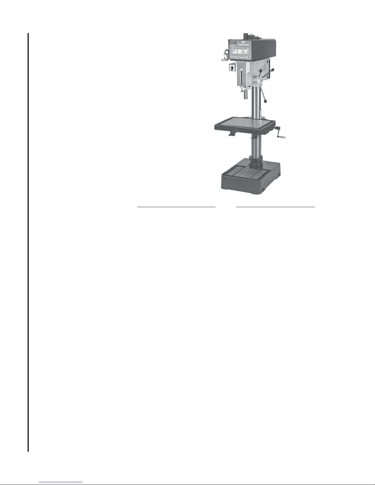
General
Specifications
The JET 20 Inch Variable Speed Drill presses
Models J-2221VS, J-2223VS, J-2232AC, and
J-2234AC are available in manual speed control
or inverter speed control configuration. Electrical
power options are single-phase, 115 and 220
volts, or 3-phase, 440 volts.
Specifications
Manual Speed Control Models Inverter Speed Control Models
Model J-2221VS J-2223VS J-2232AC J-2234AC
Stock Number .............................................354221 ................. 354223 ....................354214 ................. 354216
Drilling Capacity
Cast Iron ............................................. 1-1/4 In. ................ 1-1/4 In. ...................1-1/2 In. ................ 1-1/2 In.
Steel .................................................... 1 In. ....................... 1 In. ..........................1-3/8 In. ................. 1-3/8 In.
Spindle to Table (Max.) ................................. 32-3/8 In. ............... 32-3/8 In. .................. 32-3/8 In. ............... 32-3/8 In.
Spindle to Base (Max.) ................................ 44-1/2 In. ............... 44-1/2 In. .................. 44-1/2 In. ............... 44-1/2 In.
Spindle to Column (Max.) ............................ 10-7/16 In. ............. 10-7/16 In. ................ 10-7/16 In. ............. 10-7/16 In.
Motor
Rating .................................................. 2 hp, 1-Phase ........ 2 hp, 3-Phase .......... 2 hp, 3-Phase .......2 hp, 3-Phase
Voltage ................................................ 115/220 V .............. 220/440V .................. 220V...................... 440V
Pre-wired Voltage ................................ 115 V ..................... 220V ........................ 220V ...................... 440V
T-Slots (Table/Base)
Number ............................................... 2............................ 2 ..............................2 ............................ 2
Size ..................................................... 5/8 In. .................... 5/8 In. ....................... 5/8 In. .................... 5/8 In.
Column Diameter ........................................ 4-1/2 In. ................. 4-1/2 In. ....................4-1/2 In. ................. 4-1/2 In.
Spindle
4
Travel .................................................. 6 In. ....................... 6 In. .......................... 6 In. ....................... 6 In.
Taper ................................................... MT-3 ...................... MT-3 ......................... MT-3 ...................... MT-3
RPM (Variable) .................................... 300-2000 ............... 300-2000 .................. 65-2000 ................. 65-2000
Quill
Diameter ............................................. 3 In. ....................... 3 In. ..........................3 In. ....................... 3 In.
Travel .................................................. 6 in. ....................... 6 in. ..........................6 in. ....................... 6 in.
Table
Overall ................................................. 22x18-3/4 In. .......... 22x18-3/4 In. ............ 22x18-3/4 In. .......... 22x18-3/4 In.
Working Surface .................................. 18-1/8x14-3/4 ........ 18-1/8x14-3/4 ...........18-1/8x14-3/4 ........ 18-1/8x14-3/4
Travel .................................................. 32-3/8 In. ............... 32-3/8 In. ..................32-3/8 In. ............... 32-3/8 In.
Base
Overall ................................................. 26x19 In. ................ 26x19 In. ..................26x19 In. ................ 26x19 In.
Working Surface .................................. 15-1/4x12-1/16 ...... 15-1/4x12-1/16 ......... 15-1/4x12-1/16 ...... 15-1/4x12-1/16
Overall Dimensions
Length ................................................. 34-1/4 In. ............... 34-1/4 In. .................. 36-5/8 In. ............... 36-5/8 In.
Width ................................................... 27 In. ..................... 27 In. ........................ 27 In. ..................... 27 In.
Height .................................................. 77-1/4 In. ............... 77-1/4 In. ..................82-1/4 In. ............... 82-1/4 In.
Weight
Net ...................................................... 715 lbs.(325 kgs). 715 lbs.(325 kgs) ...715 lbs.(325 kgs) . 715 lbs.(325 kgs)
Gross .................................................803 lbs.(365 kgs) . 803 lbs.(365 kgs) ... 792 lbs.(360 kgs) . 792 lbs.(360 kgs)

- Misuse of this machine can cause serious injury.
- For safety, machine must be set up, used and
serviced properly.
- Read, understand and follow instructions in the
Operating Instructions and Parts Manual which
was shipped with your machine.
supply while servicing.
- Always follow instructions in Operating Instructions
and Parts Manual when changing accessory tools
or parts.
- Never modify the machine without consulting JET
Corporation.
When setting up machine:
- Always avoid using machine in damp or poorly
lighted work areas.
- Always be sure the machine support is securely
anchored to the floor or the work bench.
When using machine:
- Always wear safety glasses with side shields (See
ANSI Z87.1)
- Never wear loose clothing or jewelry.
- Never overreach—you may slip and fall.
When servicing machine:
- Always disconnect the machine from its electrical
You—the stationary power tool user—
hold the key to safety.
Read and follow these simple rules for best results
and full benefits from your machine. Used properly,
JET’s machinery is among the best in design and
safety. However, any machine used improperly can
be rendered inefficient and unsafe. It is absolutely
mandatory that those who use our products be
properly trained in how to use them correctly. They
should read and understand the Operating Instructions and Parts Manual as well as all labels affixed to
the machine. Failure in following all of these warnings
can cause serious injuries.
Machinery general safety warnings
1. Always wear protective eye wear when operating
machinery. Eye wear shall be impact resistant,
protective safety glasses with side shields which
comply with ANSI Z87.1 specifications. Use of
eye wear which does not comply with ANSI Z87.1
specifications could result in severe injury from
breakage of eye protection.
2. Wear proper apparel. No loose clothing or
jewelry which can get caught in moving parts.
Rubber soled footwear is recommended for best
footing.
3. Do not overreach. Failure to maintain proper
working position can cause you to fall into the
machine or cause your clothing to get caught —
pulling you into the machine.
4. Keep guards in place and in proper working
order. Do not operate the machine with guards
removed.
5. Avoid dangerous working environments. Do not
use stationary machine tools in wet or damp
locations. Keep work areas clean and well lit.
6. Avoid accidental starts by being sure the start
switch is “OFF” before plugging in the machine.
7. Never leave the machine running while unat-
tended. Machine shall be shut off whenever it is
not in operation.
8. Disconnect electrical power before servicing.
Whenever changing accessories or general
maintenance is done on the machine, electrical
9. Maintain all machine tools with care. Follow all
10. Machinery must be anchored to the floor.
11. Secure work. Use clamps or a vise to hold work,
12. Never brush away chips while the machine is in
13. Keep work area clean. Cluttered areas invite
14. Remove adjusting keys and wrenches before
15. Use the right tool. Don’t force a tool or attach-
16. Use only recommended accessories and follow
17. Keep hands in sight and clear of all moving parts
18. All visitors should be kept at a safe distance from
19. Know the tool you are using — its application,
power to the machine must be disconnected
before work is done.
maintenance instructions for lubricating and the
changing of accessories. No attempt shall be
made to modify or have makeshift repairs done to
the machine. This not only voids the warranty but
also renders the machine unsafe.
when practical. It is safer than using your hands
and it frees both hands to operate the machine.
operation.
accidents.
turning machine on.
ment to do a job it was not designed for.
manufacturers instructions pertaining to them.
and cutting surfaces.
the work area. Make workshop completely safe
by using padlocks, master switches, or by
removing starter keys.
limitations, and potential hazards.
5
General electrical cautions
This drill press should be grounded in accordance with the National Electrical Code and local codes and
ordinances. This work should be done by a qualified electrician. The saw should be grounded to protect the
user from electrical shock.
Wire sizes
Caution: for circuits which are far away from the electrical service box, the wire size must be increased in
order to deliver ample voltage to the motor. To minimize power losses and to prevent motor overheating and
burnout, the use of wire sizes for branch circuits or electrical extension cords according to the following table is
recommended.
AWG (American wire gauge) number
Conductor length 240 volt lines 120 volt lines
0-50 feet No. 14 No. 14
50-100 feet No. 14 No. 12
Over 100 feet No. 12 No.8
Safety Instructions for Drill Presses
1. All work shall be secured using either clamps or
a vise to the drill press table. It is unsafe to use
your hands to hold any workpiece being drilled.
2. Drill press head and table shall be securely
locked to the column before operating the drill press.
This must always be checked prior to starting the
machine.
3. Always use the correct tooling. Tooling shall
always be maintained and properly sharpened. All
tooling must be run at the proper speeds and feeds
as they apply to the job. Use only recommended
accessories and follow those manufacturers instructions pertaining to them. Tooling shall be not be
forced in to any workpiece but fed according to the
proper specifications. Failure to follow these
instructions will not only ruin the tooling as well as
6
the machine, but can cause serious injury.
4. Never brush away any chips while the machine
is in operation. All clean up should be done when
the machine is stopped.
5. Keep hands in sight. Do not put hands or fingers
around, on, or below any rotating cutting tools.
Leather safety gloves should be used when handling
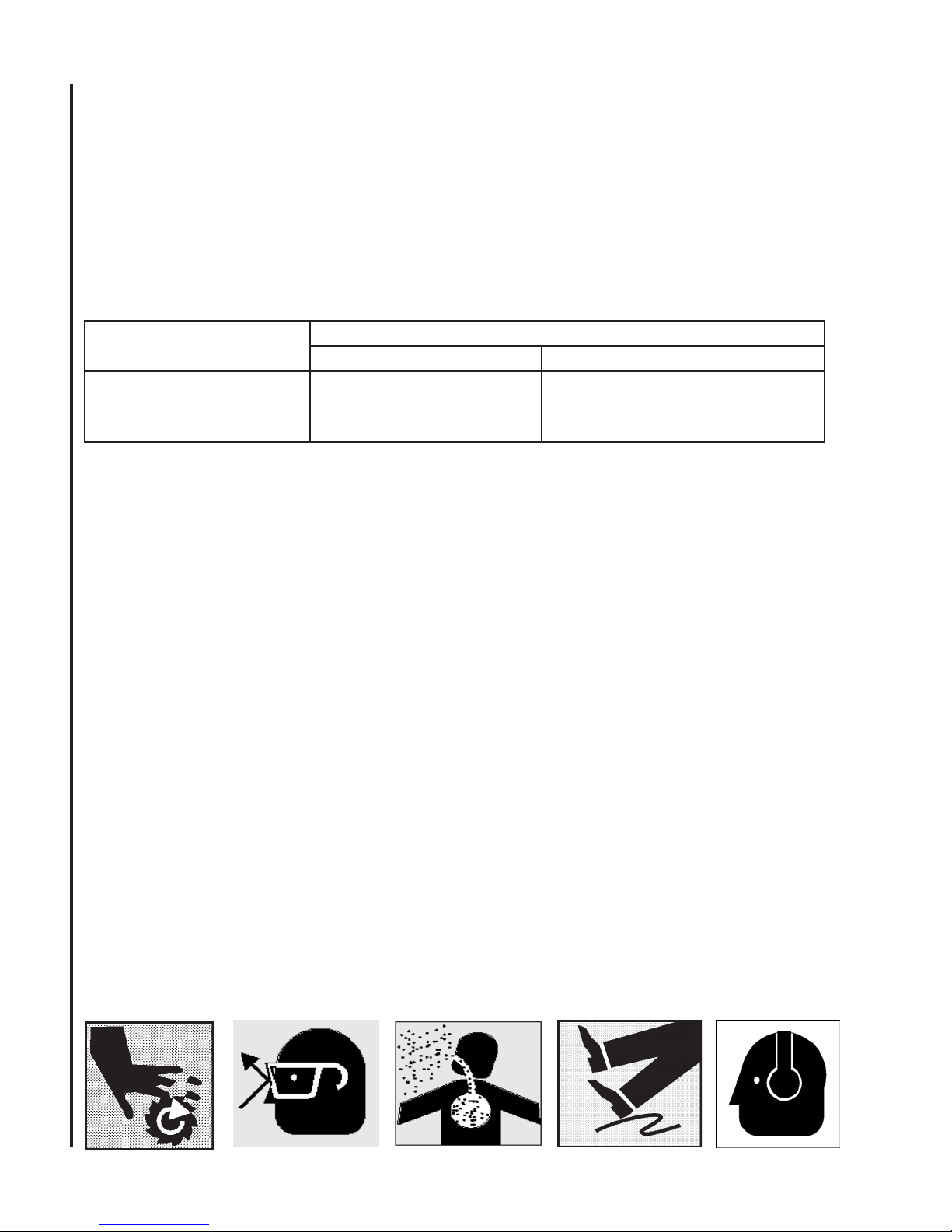
any sharp objects or cutting tools. See Figure A.
6. Always wear protective eye wear when operating,
servicing or adjusting machinery. Eyewear shall be
impact resistant, protective safety glasses with side
shields complying with ANSI Z87.1 specifications.
Use of the eye wear which does not comply with
ANSI Z87.1 specifications could result in severe
injury from breakage of eye protection. Figure B.
7. When drilling in material which causes dust, a
dust mask shall be worn. See Figure C.
8. Avoid contact with coolant, especially guarding the
eyes.
9. Non-slip footwear and safety shoes are recommended. See Figure D.
10. Wear ear protectors (plugs or muffs) during
extended periods of operation. See Figure E.
A B C
D E
Introduction
This manual includes operating and maintenance
instructions for the JET Model J-2221VS, J2223VS, J-2232AC and J-2234AC Variable Speed Drill
Presses. This manual also includes parts listings
and illustrations of replaceable parts.
Operation and Set-up
Securing the Base
JET Model J-2221VS and J-2223VS drill presses
feature manual speed control. Models J-2232AC and
J-2234AC have inverter speed control. This manual
contains procedures for both speed control versions.
The manual provides separate instructions when
differences in operation and maintenance exist.
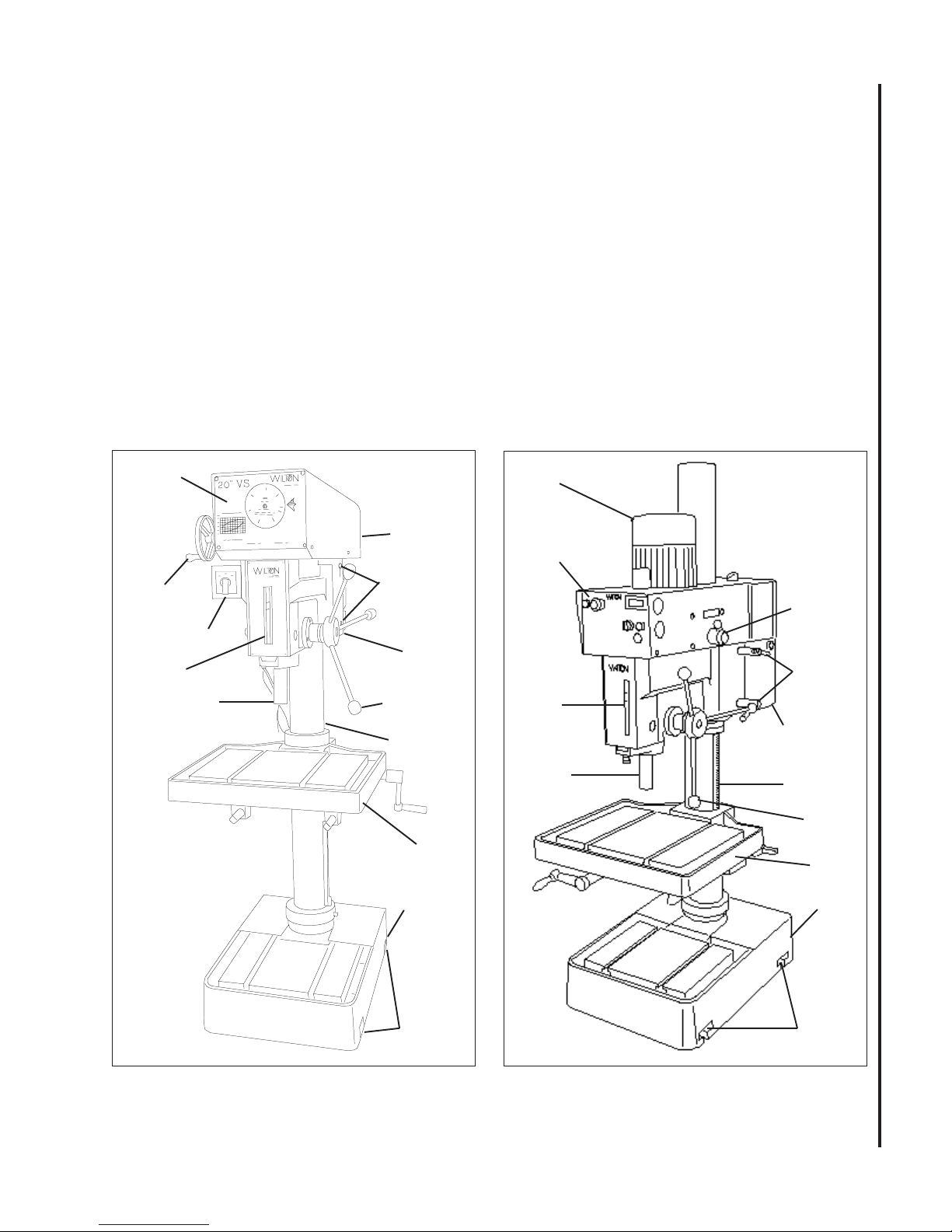
Refer to Figures 1 and 2 for key features of the drill
press.
Control
Panel
Speed
Adjustment
Handwheel
Switch
Depth
Indicator
Spindle
Electrical
Enclosure
(hidden, far
side)
Drill
Head
Head
Clamping
Nuts (2)
Drive
Motor
Spindle
Handle
Column
The base of the drill press has four mounting slots;
two slots on both sides of the base. The drill press
should be level and rest solidly on the floor. Place
shims under the four mounting slots in the base as
needed to level the drill press.
When securing the base to the floor, apply even
torque to the fasteners to prevent distortion of the
base.
Drive
Motor
Control Panel
Speed
Shift Lever
Head
Clamping
Depth
Indicator
Spindle
Nuts (2)
Electrical
Enclosure
Column
Figure 1: Drill Press Features
(Manual Speed Control Model)
Work
Table
Base
Mounting
Slots (4)
Figure 2: Drill Press Features
(Inverter Speed Control Model)
Spindle
Handle
Work
Table
Base
Mounting
Slots (4)
7

Raising the Drill Head and
Table
The drill press is shipped with the table and drill head
supported by wooden blocks near the bottom of the
column.
The head is raised to the operating position using a
strap and hoist, then secured to the column by
tighening the hex cap screw . The table is raised to
the desired position using the crank handle.
Electrical Connection
Refer to the Wiring Diagram section for wiring
information.
Speed Indicator
An LED spindle speed indicator is provided on the front
panel. The LED indicates speeds from 300 to 2000
rpm.
A selector switch is provided at the left side of the drill
head. The two-position switch is used to start and
stop the drive motor.
Speed Control Handle
CAUTION: TO AVOID DAMAGE TO THE SPEED
ADJUSTMENT MECHANISM, THE DRIVE MOTOR
MUST BE OPERATING BEFORE ATTEMPTING TO
ADJUST THE SPEED SETTING.
Models J-2221VS (manual control) and J-2232AC
(inverter control) are pre-wired for 115 volts. Models
J-2223VS (manual control) and J-2234AC (inverter
control) are pre-wired for 220 volts.
Connection of electrical power should be made by a
qualified electrician. Observe local electrical codes
when connecting the machine.
Operating Controls
(Refer to Figures 3, 4, and 5)
Manual Speed Control - Models J-2221VS
A speed control handle is provided on the front of the
head. The handle is turned clockwise to increase
spindle speed and counterclockwise to reduce speed.
To set the speed, the speed control handle is turned
until the pointer is at the desired speed.
Inverter Speed Control - Models J-2232
and J-2234 (Refer to Figure 2)
Front Panel
The front panel is mounted on the front of the drill
head. The panel contains all the controls required to
operate the drill press. There are additional controls
and J-2223VS (See Figure 3)
Speed
Spindle Selector Switch
A three-position selector switch is provided at the left
side of the drill head. It is used to select spindle rotation: reverse (REV), off (OFF), and forward (FWD).
8
Speed Control Hand Wheel
CAUTION: TO AVOID DAMAGE TO THE SPEED
ADJUSTMENT MECHANISM, THE DRIVE MOTOR
MUST BE OPERATING BEFORE ATTEMPTING TO
ADJUST THE SPEED SETTING.
Control
Handwheel
A speed control hand wheel is provided on the left
front of the head (refer to Figure 3 for location). The
handle is turned clockwise to increase spindle speed
and counterclockwise to educe speed. To set the
speed, the speed control handle is turned until the
pointer on the front panel is at the desired speed.
Drive
Motor
Switch
Figure 3: Control Panel (Manual Speed Control)
Inverter Speed Control - Models
J-2232AC and J-2234AC
Spindle On Pushbutton Switch
The SPINDLE ON pushbutton (green) is used to start
the drive motor. To stop the motor, the pushbutton is
pressed (the switch toggles on and off).
(See Figure 4)
Drilling Speed Chart
A DRILLING SPEED CHART is provided on the front
panel. The chart can be used to select the speed
required for various drill sizes (0.196 inch to 1.000
inch — 5 mm to 25 mm) and materials (steel, cast
iron, aluminum, and copper). The chart defines
spindle speeds from 300 to 3000 RPM.
Emergency Stop Pushbutton Switch
The mushroom-shaped EMG. STOP pushbutton
switch provides a quick means of stopping the drive
motor.
Inverter On Indicator
The INVERTER ON light (red) indicates that the
inverter is powered up.
RPM Display
The spindle speed display shows the spindle rpm
selected by the spindle control knob (below).
Spindle Speed Knob
The SPINDLE SPEED knob is used to set the desired
spindle speed. The speed indicator to the right of the
SPINDLE SPEED knob displays the spindle speed
setting.
Emergency Stop
Pushbutton Switch
Inverter
On Light
RPM Display
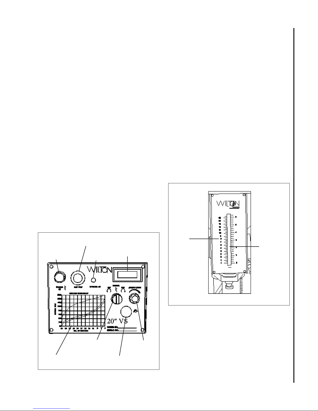
Depth Indicator —
All Models (See Figure 5)
A drilling depth indicator is provided on the front of
the drill head. The indicator can be set for depths up
to 6.5 inches (16.5 mm). A knurled knob is provided
at the at the front, underside of the head. Before
starting the motor, set the end of the drill against the
surface into which the hole is to be drilled. The
indicator is zeroed out using the knurled knob. The
motor is started and the hole drilled until the indicator
pointer reaches the desired depth.
Depth
Scale
Indicator
Spindle Direction
Selector
Drilling Speed Chart
Figure 4: Control Panel (Inverter Speed Control)
Emergency Stop
Pushbutton
9
Figure 5: Depth Indicator
Speed
Control
 Loading...