

This .pdf document is bookmarked
Operating Instructions and Parts Manual
Step-Pulley Industrial Drill Presses
Models IDP-17 and IDP-22
JET
427 New Sanford Road
LaVergne, Tennessee 37086 Part No. M-354300
Ph.: 800-274-6848 Edition 5 04/2020
www.jettools.com Copyright © 2017 JET
IDP-22
IDP-17

1.0 IMPORTANT SAFETY
INSTRUCTIONS
READ ALL INSTRUCTIONS BEFORE USING THIS
DRILL PRESS.
WARNING – To reduce risk of injury:
1. Read and understand entire owner’s manual
before attempting assembly or operation of this
drill press.
2. Read and understand the warnings posted on
the machine and in this manual.
3. Replace warning labels if they become
obscured or removed.
4. This drill press is designed and intended for use
by properly trained and experienced personnel
only. If you are not familiar with the proper and
safe operation of a drill press, do not use until
proper training and knowledge have been
obtained.
5. Do not use this drill press for other than its
intended use. If used for other purposes, JET
disclaims any real or implied warranty and holds
itself harmless from any injury that may result
from that use.
6. Always wear ANSI Z87.1 approved safety
glasses or face shield while using this drill
press. (Everyday eyeglasses only have impact
resistant lenses; they are not safety glasses.)
7. Before operating this drill press, remove tie,
rings, watches and other jewelry, and roll
sleeves up past the elbows. Remove loose
clothing and confine long hair. Non-slip
footwear or anti-skid floor strips are
recommended. Do not wear gloves.
8. Wear hearing protection (plugs or muffs) during
extended periods of operation.
9. Do not operate this machine while tired or under
the influence of drugs, alcohol or any
medication.
10. Make certain the switch is in the OFF position
before connecting the machine to the power
supply. Turn off all controls before unplugging.
11. Make certain the machine is properly grounded.
Connect to a properly grounded outlet only. See
Grounding instructions.
12. Make all machine adjustments or maintenance
with the machine unplugged from the power
source.
13. Remove adjusting keys and wrenches. Form a
habit of checking to see that keys and adjusting
wrenches are removed from the machine
before turning it on.
14. Keep safety guards in place at all times when
the machine is in use. If removed for
maintenance purposes, use extreme caution
and replace the guards immediately after
maintenance is complete.
15. Check damaged parts. Before further use of the
machine, a guard or other part that is damaged
should be carefully checked to determine that it
will operate properly and perform its intended
function. Check for alignment of moving parts,
binding of moving parts, breakage of parts,
mounting and any other conditions that may
affect its operation. A guard or other part that is
damaged should be properly repaired or
replaced.
16. Provide for adequate space surrounding work
area and non-glare, overhead lighting.
17. Keep the floor around the machine clean and
free of scrap material, oil and grease.
18. Keep visitors a safe distance from the work
area. Keep children away.
19. Make your workshop child proof with padlocks,
master switches or by removing starter keys.
20. Give your work undivided attention. Looking
around, carrying on a conversation and “horseplay” are careless acts that can result in serious
injury.
21. The drill press is intended for indoor use. To
reduce the risk of electric shock, do not use
outdoors or on wet surfaces.
22. Do not handle plug or machine with wet hands.
23. Use recommended accessories; improper
accessories may be hazardous.
24. Maintain tools with care. Follow instructions for
lubricating and changing accessories.
25. Turn off machine and disconnect from power
before cleaning. Use a brush or rag to remove
chips or debris; do not use bare hands. Do not
use compressed air.
26. Never leave the machine running unattended.
Turn the power off and do not leave the
machine until it comes to a complete stop.
27. Do not stand on the machine. Serious injury
could occur if the machine tips over.
28. Make sure the workpiece is securely attached
or clamped to the table. Never use your hand to
hold the workpiece – the bit may seize in the
workpiece and rotate, causing injury.
2
29. Secure the drill press to the floor if there is any
tendency for it to tip over, walk or slide during
operation.
30. The drill press is intended for industrial use
only.
31. Use proper extension cord. Make sure your
extension cord is in good condition. When using
an extension cord, be sure to use one heavy
enough to carry the current your product will
draw. An undersized cord will cause a drop in
line voltage resulting in loss of power and
overheating. Table 1 (sect. 7.3) shows correct
size to use depending on cord length and
nameplate ampere rating. If in doubt, use the
next heavier gage. The smaller the gage
number, the heavier the cord.
WARNING: This product can expose you to
chemicals including lead which is known to the
State of California to cause cancer and birth
defects or other reproductive harm. For more
information go to http://www.p65warnings.ca.
gov.
WARNING: Some dust, fumes and gases
created by power sanding, sawing, grinding,
drilling, welding and other construction activities
contain chemicals known to the State of
California to cause cancer and birth defects or
other reproductive harm. Some examples of
these chemicals are:
lead from lead based paint
crystalline silica from bricks, cement and
other masonry products
arsenic and chromium from chemically
treated lumber
Your risk of exposure varies, depending on how
often you do this type of work. To reduce your
exposure to these chemicals, work in a wellventilated area and work with approved safety
equipment, such as dust masks that are
specifically designed to filter out microscopic
particles. For more information go to
http://www.p65warnings.ca.gov/ and http://
www.p65warnings.ca.gov/wood.
Familiarize yourself with the following safety notices used in this manual:
This means that if precautions are not heeded, it may result in minor injury and/or possible
machine damage.
This means that if precautions are not heeded, it may result in serious, or possibly even fatal,
injury.
SAVE THESE INSTRUCTIONS
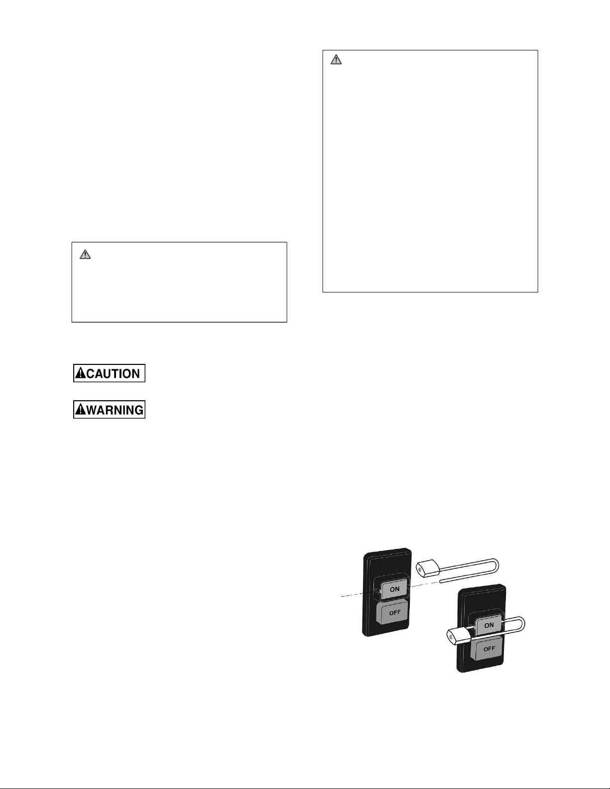
2.0 On-off switch padlock
To avoid accidental starting by young children or others not qualified to use the tool, the use of a padlock (not
provided) is required.
To lock out the on-off switch (Figure 2-1):
1. Open padlock.
2. Insert through hole in switch guard.
3. Close padlock.
4. Store key in a safe place out of the reach of
children.
Figure 2-1
3

3.0 About this manual
This manual is provided by JET, covering the safe operation and maintenance procedures for a JET Model IDP17 and IDP-22 Drill Press. This manual contains instructions on installation, safety precautions, general operating
procedures, maintenance instructions and parts breakdown. The drill press has been designed and constructed
to provide consistent, long-term operation if used in accordance with the instructions as set forth in this document.
If there are questions or comments, please contact your local supplier or JET. JET can also be reached at our
web site: www.jettools.com.
Retain this manual for future reference. If the machine transfers ownership, the manual should accompany it.
4.0 Table of contents
Section Page
1.0 IMPORTANT SAFETY INSTRUCTIONS ....................................................................................................... 2
2.0 On-off switch padlock ..................................................................................................................................... 3
3.0 About this manual .......................................................................................................................................... 4
4.0 Table of contents ............................................................................................................................................ 4
5.0 Specifications ................................................................................................................................................. 5
5.1 Base mounting hole dimensions ................................................................................................................ 6
6.0 Setup and assembly ....................................................................................................................................... 7
6.1 Unpacking and cleanup .............................................................................................................................. 7
6.2 Shipping contents ....................................................................................................................................... 7
6.3 Tools required for assembly: ...................................................................................................................... 7
6.4 Assembly .................................................................................................................................................... 7
7.0 Electrical connections .................................................................................................................................... 8
7.1 GROUNDING INSTRUCTIONS ................................................................................................................. 8
7.2 Voltage conversion ..................................................................................................................................... 8
7.3 Extension cords .......................................................................................................................................... 9
8.0 Adjustments ................................................................................................................................................... 9
8.1 Depth stop adjustment ............................................................................................................................... 9
8.2 Changing spindle speeds ........................................................................................................................... 9
8.3 Return spring adjustment ......................................................................................................................... 10
8.4 Table tilt adjustment ................................................................................................................................. 10
9.0 Operating controls ........................................................................................................................................ 10
10.0 Operation ................................................................................................................................................... 10
11.0 User-maintenance ...................................................................................................................................... 11
11.1 Lubrication .............................................................................................................................................. 11
11.2 Belt replacement .................................................................................................................................... 11
12.0 Spindle speed charts .................................................................................................................................. 12
12.1 Speed selection for IDP-17 Drill Press .................................................................................................... 12
12.2 Speed selection for IDP-22 Drill Press ................................................................................................... 12
13.0 Troubleshooting IDP-17, IDP-22 ................................................................................................................ 13
14.0 Replacement Parts ..................................................................................................................................... 14
14.1.1 IDP-17 Drill Press – Exploded View .................................................................................................... 15
14.1.2 IDP-17 Drill Press – Parts List ............................................................................................................. 16
14.2.1 IDP-22 Drill Press – Exploded View .................................................................................................... 18
14.2.2 IDP-22 Drill Press – Parts List ............................................................................................................. 19
15.0 Electrical Connections for IDP-17, IDP-22 ................................................................................................. 21
16.0 Warranty and service ................................................................................................................................. 22
4

5.0 Specifications
Model number ............................................................................... IDP-17 ............................................................ IDP-22
Stock number ............................................................................... 354300 ........................................................... 354301
Motor and electricals:
Motor type…………………………………………………….totally enclosed fan cooled, induction, capacitor start .........
Horsepower .................................................................................. 1 HP ......................................................... 1-1/2 HP
Phase .......................................................................................... single ............................................................. single
Voltage ........................................................ 115/230V (prewired 115V) ............................. 115/230V (prewired 115V)
Cycle ............................................................................................ 60Hz .............................................................. 60Hz
Listed FLA (full load amps) ......................................................... 17.2 A ............................................................ 12.4 A
Starting amps ............................................................................... 9.0 A ............................................................. 7.4 A
Running amps (no load) ............................................................... 8.9 A ............................................................. 7.6 A
Start capacitor ......................................................... 300 MFD 125VAC .......................................... 400 MFD 125VAC
Run capacitor ................................................................. 30F 250VAC ................................................ 40F 250VAC
Power transfer .............................................................................. v-belt .............................................................. v-belt
On/off switch ....................................................................... push button .................................................... push button
Motor speed......................................................................... 1720 RPM ...................................................... 1720 RPM
Main power cord ................................ 18 AWG, 6 ft. (183 cm) with plug .................... 14AWG, 6 ft. (183 cm) with plug
Work lamp power cord ....................... 18 AWG, 6 ft. (183 cm) with plug ................... 18 AWG, 6 ft. (183 cm) with plug
Recommended circuit size
Sound emission ......................................... 70 dB at 40 in. without load ............................ 70 dB at 40 in. without load
Work lamp ......................................................................... 110V to 12V ................................................... 110V to 12V
Head and Capacities:
Swing 2 .................................................................. 16-7/8 in. (430 mm) ........................................ 21-7/8 in. (560 mm)
Chuck style and shank capacity ............................ keyed, 5/8” (16mm) ........................................ keyed, 5/8” (16mm)
Chuck arbor taper .............................................................. JT-3 to MT2 .................................................... JT-3 to MT3
Spindle taper ................................................................................. MT2 ................................................................ MT3
Spindle travel, maximum ......................................... 3-5/16 in. (85 mm) ...................................... 4-13/16 in. (122 mm)
Spindle travel per one revolution of handle ..................... 3 in. (78 mm) .......................................... 4-1/2 in. (115 mm)
Quill diameter .......................................................... 2-1/16 in. (52 mm) ............................................ 2-5/8 in. (62 mm)
Number of spindle speeds ................................................................ 12 ................................................................... 12
Maximum no-load speed range ................................. 350 to 2800 RPM ........................................... 175 to 3050 RPM
Maximum spindle to table distance ........................ 30-1/2 in. (775 mm) .............................................. 28 in. (710 mm)
Maximum spindle to base distance ............................ 50 in. (1270 mm) ...................................... 48-1/2 in. (1230 mm)
Maximum chuck to table distance ................................ 27 in. (686 mm) ........................................ 24-1/2 in. (622 mm)
Maximum chuck to base distance ........................ 46-1/2 in. (1181 mm) .............................................. 39 in. (990 mm)
Drilling capacity, cast iron ............................................. 3/4 in. (20 mm) ............................................ 1-1/4 in. (32 mm)
Drilling capacity, mild steel ........................................... 5/8 in. (16 mm) .................................................. 1 in. (25 mm)
Work lamp ................................................................... LED, adjustable .............................................. LED, adjustable
Materials:
Head ........................................................................................ cast iron ......................................................... cast iron
Table .............................................................. surface-ground cast iron ................................ surface-ground cast iron
Column .......................................................................................... steel ............................................................... steel
Base ........................................................................................ cast iron ......................................................... cast iron
Table:
Table size ................................................... 14 x 14 in. (355 x 355 mm) ................ 18-5/8 x 16-1/8 in. (473 x 410 mm)
Table slots, number of ........................................................................ 2 ..................................................................... 3
Table slots, general size (WxD) .................... 1/2 x 1 in. (13 x 25.4 mm) .............................. 5/8 x 1 in. (16 x 25.4 mm)
T-slot dimensions (WxD) .............................. 3/4 x 3/8 in. (19 x 9.5mm) ............................. 1 x 3/8 in. (25.4 x 9.5 mm)
Distance between slots (centers) ............................... 3-7/8 in. (98 mm) ............................................ 3-1/2 in. (91 mm)
Table tilt ....................................................................... 45 deg. L and R ............................................. 45 deg. L and R
Table rotation around column ................................................. 360 deg. ......................................................... 360 deg.
Table elevating system ......................................... worm gear with rack ....................................... worm gear with rack
Recommended maximum weight on table ...................... 110 lb. (50 kg) ................................................ 176 lb. (80 kg)
1
Subject to local and national electrical codes
2
Swing is twice the distance from column to spindle center (i.e., the maximum diameter of workpiece that can be
drilled to its center).
1
........................................................... 20A ................................................................ 20A
5
Base and Column:
Base size (LxWxH) ..................................... 21-3/4 x 13-3/4 x 2-3/16 in. ............................ 22-5/8 x 19-7/16 x 3-3/8 in.
............................................................................. (553 x 350 x 56 mm) ...................................... (575 x 494 x 86 mm)
Base working surface ............. 16-15/16 x 10-13/16 in. (430 x 275 mm) .............. 21-1/2 x 18-5/16 in. (545 x 465 mm)
Base slots, number of ......................................................................... 2 ..................................................................... 2
Base slots, general size (WxD) ..................... 1/2 x 1 in. (13 x 25.4 mm) .............................. 5/8 x 1 in. (16 x 25.4 mm)
T-slot dimensions (WxD) .............................. 3/4 x 3/8 in. (19 x 9.5mm) ............................. 1 x 3/8 in. (25.4 x 9.5 mm)
Distance between base slots (centers) .................... 5-7/8 in. (149 mm) ......................................... 9-3/4 in. (238 mm)
Column diameter ....................................................... 3-1/8 in. (80 mm) ............................................ 3-5/8 in. (92 mm)
Dimensions and Weights:
Overall dimensions, assembled ........................ 27-1/2 x 15-3/4 x 63 in. ............................................... 35 x 19 x 67 in.
......................................................................... (700 x 400 x 1600 mm) ................................. (890 x 480 x 1700 mm)
Shipping dimensions ........................................ 31-1/2 x 16-3/4 x 70 in. ............................ 36-5/8 x 20-7/8 x 74-1/2 in.
......................................................................... (800 x 425 x 1780 mm) .................................. (930 x 530 x 1890 mm)
Net weight (approximate) ............................................. 231 lb. (105 kg) .............................................. 319 lb. (145 kg)
Shipping weight (approximate) ..................................... 260 lb. (118 kg) .............................................. 364 lb. (165 kg)
L = length; W = width; H= height; D= depth
The specifications in this manual were current at time of publication, but because of our policy of continuous
improvement, JET reserves the right to change specifications at any time and without prior notice, without
incurring obligations.
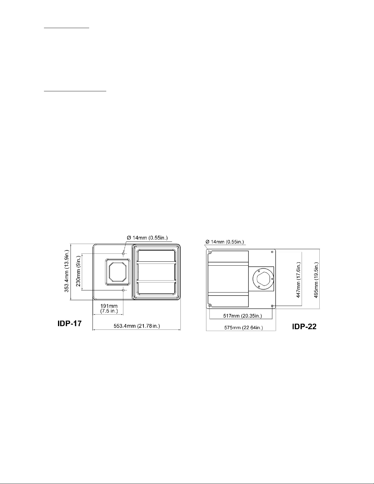
5.1 Base mounting hole dimensions
Figure 5-1: Base hole patterns
6
Read and understand the
entire contents of this manual before attempting
assembly or operation. Failure to comply may
cause serious injury.
6.0 Setup and assembly
6.1 Unpacking and cleanup
Remove all contents from shipping carton and
compare parts to the contents list in this manual. If
shipping damage or any part shortages are
identified, contact your distributor. Do not discard
carton or packing material until drill press is
assembled and running satisfactorily.
Clean all rust protected surfaces with kerosene or a
light solvent. Do not use lacquer thinner, paint
thinner or gasoline, as these can damage plastic
components and painted surfaces.
6.2 Shipping contents
Carton contents
1 Drill press
1 Crank handle
3 Feed handles
1 Chuck and key
1 Arbor
1 Wrench
1 Drift key
2 Hex wrenches – 3mm, 5mm
1 Owner’s manual
1 Warranty registration card
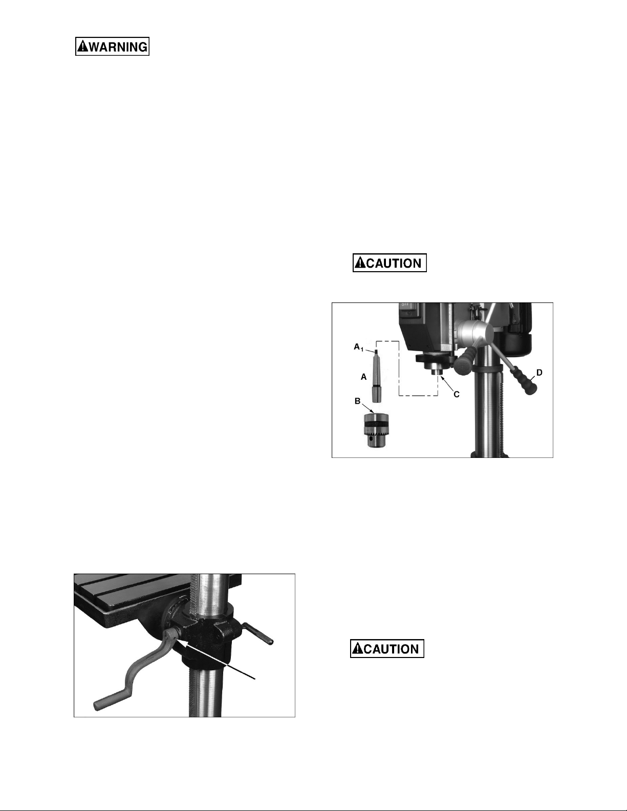
6.4.1 Chuck and arbor installation
1. Thoroughly clean arbor (A, Figure 6-2), chuck
(B) and spindle (C). Any grease or residue in
these areas can cause the pieces to separate
and create a safety hazard as well as damage
to the tool.
3. Twist chuck to retract chuck jaws if they are
exposed.
4. Push chuck (B) by hand onto arbor (A), and
slide assembly firmly up into spindle (C).
5. Turn arbor and chuck assembly until tang (A
on arbor engages slot at end of spindle.
6. Use one or two sharp taps from a rubber mallet,
or a hammer and a block of wood, against
bottom of chuck to seat chuck securely onto
arbor.
Do not use a steel hammer
directly against chuck, as this may damage
chuck.
)
1
6.3 Tools required for assembly
3mm hex wrench (provided)
Rubber mallet
6.4 Assembly
1. Install 3 feed handles into hub (D, Figure 6-2).
2. Install crank handle on shaft of table bracket,
and tighten set screw with 3mm hex wrench.
(Figure 6-1)
Figure 6-1: installing crank handle
Figure 6-2: installing chuck and arbor
6.4.2 Chuck and arbor removal
1. Unplug machine from power source.
2. Raise table until it is about seven inches below
chuck.
3. Place a piece of scrap wood on table, and lower
quill (Figure 6-3) using feed handles.
4. Rotate spindle to align keyhole in spindle with
keyhole in quill.
5. Insert drift key (E, Figure 6-3) into aligned slots
and tap lightly. The chuck and arbor assembly
should fall from the spindle.
Catch chuck as it is
released; allowing it to fall to floor may
damage it.
6.4.3 Wrench and key storage
Wrenches, chuck key, and drift key can be stored on
fixture on right side of drill press head.
7
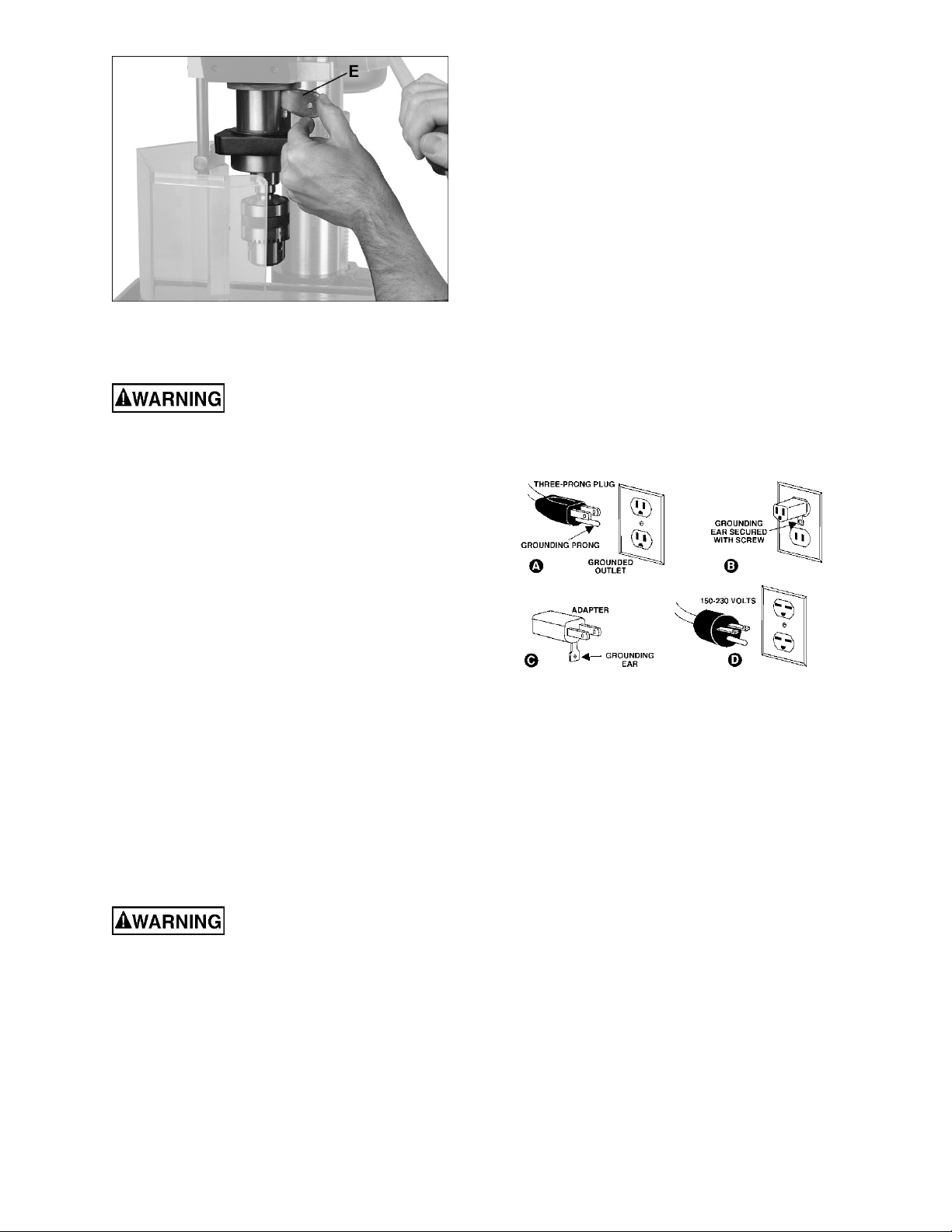
Figure 6-3: drift key insertion
7.0 Electrical connections
All electrical connections must
be done by a qualified electrician in compliance
with all local codes and ordinances. Failure to
comply may result in serious injury.
The IDP-17 and IDP-22 Drill Presses are rated at
115/230V power, and are pre-wired for 115 volt. The
drill press comes with a plug designed for use on a
circuit with a grounded outlet that looks like the one
pictured in A, Figure 7-1.
Before connecting to power source, be sure switch
is in off position.
It is recommended that the drill press be connected
to a dedicated 20 amp circuit with circuit breaker or
fuse. If connected to a circuit protected by fuses, use
time delay fuse marked “D”. Local codes take
precedence over recommendations.
7.1 GROUNDING INSTRUCTIONS
This tool must be grounded. In the event of a
malfunction or breakdown, grounding provides a
path of least resistance for electric current to reduce
the risk of electric shock. This tool is equipped with
an electric cord having an equipment-grounding
conductor and a grounding plug. The plug must be
inserted into an appropriate outlet that is properly
installed and grounded in accordance with all local
codes and ordinances.
Improper connection of the
equipment-grounding conductor can result in a
risk of electric shock. Check with a qualified
electrician or service person if you are in doubt
as to whether the outlet is properly grounded.
Do not modify the plug provided with the tool –
if it will not fit the outlet, have a proper outlet
installed by a qualified electrician.
The conductor with insulation having an outer
surface that is green with or without yellow stripes is
the equipment-grounding conductor. If repair or
replacement of the electric cord or plug is
necessary, do not connect the equipment-grounding
conductor to a live terminal.
Use only 3-wire extension cords that have 3-prong
grounding plugs and 3-pole receptacles that accept
the tool's plug.
Repair or replace damaged or worn cord
immediately.
When operated at 115-volt, this tool is intended for
use on a circuit that has an outlet that looks like the
one illustrated in A, Figure 7-1. An adapter, shown
in B and C, may be used to connect this plug to a
2-pole receptacle as shown in B if a properly
grounded outlet is not available. The temporary
adapter should be used only until a properly
grounded outlet can be installed by a qualified
electrician. The green-colored rigid ear, lug, and the
like, extending from the adapter must be connected
to a permanent ground such as a properly grounded
outlet box. Note: In Canada, the use of a temporary
adaptor is not permitted by the Canadian Electrical
Code, C22.1.
Figure 7-1: grounding
When operated at 230-volt, this tool is intended for
use on a circuit that has an outlet that looks like the
one illustrated in D, Figure 7-1. The tool has a
grounding plug that looks like the plug illustrated in
D. Make sure the tool is connected to an outlet
having the same configuration as the plug. No
adapter is available or should be used with this tool.
If the tool must be reconnected for use on a different
type of electric circuit, the reconnection should be
made by qualified service personnel; and after
reconnection, the tool should comply with all local
codes and ordinances.
7.2 Voltage conversion
Conversion from 115V to 230V must be done by
a qualified electrician.
The Drill Press is prewired for 115 volt. To change
incoming leads for 230 volt operation:
1. Open motor junction box cover, and change
leads based on wiring diagram inside cover.
This diagram is also shown in Figure 7-2.
(NOTE: In case of discrepancy, diagram inside
junction box cover takes precedence.)
8

2. Reinstall cover.
3. The plug on end of main power cord must be
replaced with a UL/CSA listed plug rated for 230
volt operation.
Figure 7-2: voltage conversion
7.3 Extension cords
The use of extension cords is discouraged; try to
position machines near the power source. If an
extension cord is necessary, make sure it is in good
condition. When using an extension cord, be sure to
use one heavy enough to carry the current your
product will draw. An undersized cord will cause a
drop in line voltage resulting in loss of power and
overheating. Table 1 shows correct size to use
depending on cord length and nameplate ampere
rating. If in doubt, use the next heavier gauge. The
smaller the gauge number, the heavier the cord.
Amp Rating Volts Total length of cord in feet
More
Than
0 6 18 16 16 14
6 10 18 16 14 12
10 12 16 16 14 12
12 16 14 12
Not
More
Than
120
240
AWG
25
50
50
100
100
200
Not
Recommended
150
300
Table 1: Extension cord recommendations
8.0 Adjustments
8.1 Depth stop adjustment
To drill multiple holes at the same preset depth, use
the depth stop:
1. Make a pencil mark on edge of workpiece to
indicate depth of hole.
2. With drill bit in chuck, lower downfeed handle to
advance bit to your mark.
3. With your other hand, advance lock nuts (A,
Figure 8-1) on the depth stop rod until they are
snug to the seat (B).
4. The drill bit will now advance to this point.
5. To release, advance nuts counterclockwise to
top of depth stop.
Figure 8-1: depth stop adjustment
8.2 Changing spindle speeds
A spindle speed and pulley/belt arrangement chart
is affixed inside pulley cover, and also shown in
sect. 12.0 of this manual.
To change spindle speeds:
1. Unplug machine from power source.
2. Loosen two thumb screws (C, Figure 8-2) found
on each side of head assembly.
3. Rotate tension handle (D) clockwise to bring
motor base as close to head as possible.
4. For desired speed, change location of belts per
pulley/belt arrangement chart.
5. Rotate tension handle (D) counterclockwise to
tension belts.
6. Tighten both thumb screws (C). Belts are
properly tensioned when finger and thumb
pressure midway between the two pulleys
causes approximately 1/2-inch deflection.
Figure 8-2: belt/speed adjustment
9

8.3 Return spring adjustment
The return spring is adjusted by the manufacturer
and should not require attention. If adjustment is
deemed necessary, follow the steps below while
referring to Figure 8-3:
1. Unplug machine from power source.
2. Loosen lock nut (E). Do not remove.
3. Firmly hold coil spring cover (F).
4. Pull out cover and rotate until pin (G) on housing
engages the next notch in coil spring cover.
Turn cover clockwise to decrease tension and
counterclockwise to increase tension.
5. Tighten lock nut (E). Do not over-tighten or
force nut too strongly against spring cover.
Figure 8-4: table tilt (IDP-17 only)
Figure 8-5: table tilt (IDP-22 only)
Figure 8-3: return spring adjustment
8.4 Table tilt adjustment
Table tilt adjustments are made on table bracket
beneath table.
Refer to Figures 8-4 and 8-5.
In the following steps do not
over-loosen. This could cause table assembly to
separate from column, fall and cause injury.
1. IDP-17: Loosen set screw (H) with 6mm hex
wrench.
IDP-22: Loosen set screw (H) with 5mm hex
wrench).
2. IDP-17: Loosen hex cap screw (J) with 23mm
or adjustable wrench.
IDP-22: Loosen two hex nuts (J) with 19mm or
adjustable wrench.
3. Tilt table to desired angle, referring to scale and
pointer atop table bracket.
4. Tighten screw or nuts (J).
5. Tighten set screw (H).
9.0 Operating controls
Press ON button to start spindle rotation. Press OFF
to stop.
The work lamp operates independently; on/off
button is on top of lamp housing.
10.0 Operation
1. Insert drill bit into chuck jaws about 1inch (25.4mm) deep. When using a small bit, do
not insert it so far that the jaws touch the flutes
of the bit. Make sure bit is centered in chuck
before tightening chuck with key.
2. For a small workpiece that cannot be clamped
to the table, use a drill press vise. The vise must
be clamped or bolted to the table. Always use a
back-up piece of scrap wood to cover the table.
This protects both table and drill bit.
Workpiece must be
clamped to table or secured in a drill press
vise that is securely fastened to table.
Failure to comply may cause serious injury.
3. Feed the bit into the material with only enough
force to allow the drill bit to work. Feeding too
slowly may cause burning of the workpiece.
Feeding too quickly may cause the motor to
stop and/or the drill bit to break.
4. Generally speaking, the smaller the drill bit, the
greater the RPM required. Soft materials
require higher speeds; hard metals slower
speeds.
10

11.0 User-maintenance
Before any intervention on the
machine, disconnect it from electrical supply by
pulling out plug or turning off main switch at
electrical source. Failure to comply may cause
serious injury.
A coat of automobile-type wax applied to table and
column will help keep surfaces clean.
Check that bolts are tight and electrical cords are in
good condition. If an electrical cord is worn, cut, or
damaged in any way, have it replaced immediately.
In dusty environments, frequently blow out any dust
that accumulates inside the motor fan cover.
Belts should be in good condition with no signs of
cracks, frays or deterioration.
11.1 Lubrication
All ball bearings are pre-lubricated and sealed, and
require no further lubrication.
Periodically apply #2 tube grease to:
Rack.
Table elevating mechanism, including worm
gear.
Splines (grooves) in spindle.
Teeth of quill.
Periodically apply light coat of machine tool oil to
quill and column.
The quill return spring should receive SAE 20 oil
once yearly. Apply the oil beneath spring cover (F,
Figure 8-3) using a squirt can.
11.2 Belt replacement
To loosen and remove the existing v-belts, use the
same procedures described in sect. 8.2, Changing
spindle speeds.
11

12.0 Spindle speed charts
12.1 Speed selection for IDP-17 Drill Press
Figure 12-1: IDP-17 only
12.2 Speed selection for IDP-22 Drill Press
Figure 12-2: IDP-22 only
12

13.0 Troubleshooting IDP-17, IDP-22
Symptom Possible Cause Correction *
Drill press unplugged from wall, or
motor.
Drill press will not
start.
Drill press does not
come up to speed.
Drill Press vibrates
excessively.
Noisy operation.
Workpiece burns or
smokes.
Drill bit wanders.
Wood splinters on the
underside.
Drill bit binds in
workpiece.
Excessive drill bit
runout, or wobble.
Quill returns too slow,
or too fast.
Chuck or arbor does
not stay in place.
* WARNING: Some corrections may require a qualified electrician.
Fuse blown, or circuit breaker tripped. Replace fuse, or reset circuit breaker.
Cord damaged. Replace cord.
Starting capacitor bad. Replace starting capacitor.
Extension cord too light or too long. Replace with adequate size and length cord.
Low current. Contact a qualified electrician.
Base on uneven surface. Locate drill press on even floor.
Bad belt(s). Replace belts.
Incorrect belt tension. Adjust belt tension.
Dry spindle. Lubricate spindle.
Loose spindle pulley.
Loose motor pulley. Tighten setscrews in pulleys.
Incorrect Speed. Change to appropriate speed.
Chips not clearing from hole or bit. Retract drill bit frequently to remove chips.
Dull drill bit. Resharpen, or replace drill bit.
Feeding too slowly. Increase feed rate.
Bit sharpened incorrectly. Resharpen bit correctly.
Bent drill bit. Replace drill bit.
Bit, or chuck not installed properly. Reinstall the chuck, or bit properly.
No backing board used.
Workpiece pinching the bit. Support or clamp workpiece.
Excessive feed rate. Decrease feed rate.
Chuck jaws not tight. Tighten chuck jaws.
Improper belt tension. Adjust belt tension.
Bent drill bit. Replace drill bit.
Worn spindle bearings. Replace spindle bearings.
Bit, or chuck not properly installed. Reinstall the bit, or chuck properly.
Improper spring tension. Adjust spring tension.
Dirt, grease, etc on arbor, chuck, or
spindle.
Table 2
Check all plug connections.
Check tightness of retaining nut on pulley, and
tighten if necessary.
Place a scrap board underneath the workpiece
to prevent splintering.
Clean all mating surfaces thoroughly with a
cleaner-degreaser.
13

14.0 Replacement Parts
Replacement parts are listed on the following pages. To order parts or reach our service department, call 1-800274-6848 Monday through Friday, 8:00 a.m. to 5:00 p.m. CST. Having the Model Number and Serial Number of
your machine available when you call will allow us to serve you quickly and accurately.
Some parts are shown for reference only, and may not be available individually.
Non-proprietary parts, such as fasteners, can usually be found at local hardware stores, or may be ordered from
JET.
14

14.1.1 IDP-17 Drill Press – Exploded View
15

14.1.2 IDP-17 Drill Press – Parts List
Index No Part No Description Size Qty
1 ................ IDP17-01 ................... Base ........................................................................ 550 x 350 x 53 mm ....... 1
201 ............ IDP17-201 ................. Column Assembly (#2, 5) ........................................ ...................................... 1
2 ................ IDP17-02 ................... Column Holder ......................................................... ...................................... 1
3 ................ TS-0732061 .............. Spring Washer ......................................................... 3/8" ................................ 4
4 ................ TS-0209072 .............. Hex Cap Screw ........................................................ 3/8" x 1-1/2" .................. 4
5 ................ IDP17-05 ................... Column .................................................................... Ø80 mm ........................ 1
6 ................ IDP17-06 ................... Rack ....................................................................... ...................................... 1
7 ................ IDP17-07 ................... Table Crank ............................................................. ...................................... 1
8 ................ TS-0267021 .............. Set Screw ................................................................ 1/4" x 1/4"...................... 1
202 ............ IDP17-202 ................. Table Assembly (#9, 11 thru 16, 17-1, 17-2) ........... ...................................... 1
9 ................ IDP17-09 ................... Table Bracket .......................................................... ...................................... 1
10 .............. IDP17-10 ................... Clamp Bolt .............................................................. 1/2" x 45 ........................ 1
11 .............. IDP17-11 ................... Tilt Angle Scale ........................................................ ...................................... 1
12 .............. IDP17-12 ................... Work Table .............................................................. 358 x 358 x 44 .............. 1
13 .............. IDP17-13 ................... Screw ....................................................................... 5/8 x 1-3/4 ..................... 1
14 .............. TS-0680081 .............. Flat Washer ............................................................. 5/8" x 30 x 3 .................. 1
15 .............. TS-0271031 .............. Set Screw ................................................................ 3/8" x 3/8"...................... 1
16 .............. IDP17-16 ................... Worm Gear Assembly ............................................. ...................................... 1
17 .............. IDP17-17 ................... Rack Collar .............................................................. ID Ø80 mm ................... 1
17-1 ........... IDP17-17-1 ................ Pinion Gear .............................................................. SC15 ............................. 1
17-2 ........... IDP17-17-2 ................ Shaft ........................................................................ ...................................... 1
18 .............. TS-0267021 .............. Set Screw ................................................................ 1/4" x 1/4"...................... 1
19 .............. IDP17-19 ................... Feed Hub ................................................................. ...................................... 1
203 ............ IDP17-203 ................. Feed Handle Assembly (#20,21) ............................. ...................................... 3
20 .............. IDP17-20 ................... Handle ..................................................................... ...................................... 3
21 .............. IDP17-21 ................... Knob ....................................................................... ...................................... 3
204 ............ IDP17-204 ................. Feed Pinion Assembly (#19,22) .............................. ...................................... 1
22 .............. IDP17-22 ................... Feed Pinion ............................................................. ...................................... 1
23 .............. IDP17-23 ................... Head Casting ........................................................... ...................................... 1
24 .............. IDP17-24 ................... Chuck Key Fixture ................................................... ...................................... 1
25 .............. 5711571 .................... Phillips Pan Head Screw ......................................... 3/16" x 1/4".................... 1
26 .............. TS-0271031 .............. Set Screw ................................................................ 3/8" x 3/8"...................... 2
27 .............. IDP17-27 ................... Tension Adjust Handle ............................................ ...................................... 1
28 .............. IDP17-28 ................... Thumb Screw .......................................................... 3/8" ................................ 2
29 .............. IDP17-29 ................... Motor Mount Plate ................................................... ...................................... 1
30 .............. IDP17-30 ................... Motor ....................................................................... 1HP 1PH 115/230V ...... 1
.................. IDP17-30-SC ............. Start Capacitor ......................................................... 300MFD 125VAC .......... 1
.................. IDP17-30-RC ............. Run Capacitor .......................................................... 30F 250VAC ............... 1
.................. IDP17-30-MF ............. Motor Fan ................................................................ ...................................... 1
.................. IDP17-30-MFC .......... Motor Fan Cover ...................................................... ...................................... 1
.................. IDP17-30-JB .............. Junction Box ............................................................ ...................................... 1
.................. IDP17-30-JBC ........... Junction Box Cover ................................................. ...................................... 1
31 .............. TS-0680031 .............. Flat Washer ............................................................. 5/16" .............................. 4
32 .............. TS-0561021 .............. Hex Nut .................................................................... 5/16" .............................. 4
33 .............. TS-0561051 .............. Hex Nut .................................................................... 1/2" ................................ 2
34 .............. TS-0680061 .............. Flat Washer ............................................................. 1/2" ................................ 2
35 .............. IDP17-35 ................... Shaft Lever .............................................................. ...................................... 1
36 .............. IDP17-36 ................... Adjusting Bolt B ....................................................... ...................................... 1
37 .............. IDP17-37 ................... Adjusting Bolt A ....................................................... ......
38 .............. TS-0680031 .............. Flat Washer ............................................................. 5/16" .............................. 4
39 .............. TS-0051011 .............. Hex Cap Screw ........................................................ 5/16" .............................. 4
40 .............. IDP17-40 ................... Phillips Pan Washer Head Screw ............................ 1/4" x 3/8"...................... 4
41 .............. IDP17-41 ................... Pulley Cover ............................................................ ...................................... 1
42 .............. IDP17-42 ................... Motor Cord ............................................................... ...................................... 1
43 .............. IDP17-43 ................... Hold Down Strip ....................................................... ...................................... 2
44 .............. 5711571 .................... Phillips Pan Head Screw ......................................... 3/16" x 1/4".................... 3
45 .............. IDP17-45 ................... Strain Relief ............................................................. ...................................... 4
46 .............. TS-1523011 .............. Set Screw ................................................................ M6 x 8 mm .................... 1
47 .............. IDP17-47 ................... Motor Pulley ............................................................. ...................................... 1
48 .............. IDP17-48 ................... Knob ....................................................................... ...................................... 1
................................ 1
16

Index No Part No Description Size Qty
49 .............. BB-6202 .................... Ball Bearing ............................................................. 6202 .............................. 1
50 .............. VB-A26 ...................... V-Belt ....................................................................... A26 ............................... 1
51 .............. IDP17-51 ................... Center Pulley ........................................................... ...................................... 1
52 .............. IDP17-52 ................... Pivot Bracket ........................................................... ...................................... 1
53 .............. TS-081F031 .............. Head Flat Screw ...................................................... 1/4" x 1/2"...................... 1
54 .............. JET-138 ..................... JET Logo with adhesive .......................................... 138 x 57 mm ................. 1
55 .............. IDP17-55 ................... Hold Down Strip ....................................................... ...................................... 1
56 .............. IDP17-56 ................... Power Cord .............................................................. 3x18AWG, 300V ........... 1
57 .............. IDP17-57 ................... Screw ....................................................................... 3/16" x 45 mm ............... 2
58 .............. IDP17-58 ................... Work Lamp .............................................................. ...................................... 1
59 .............. TS-0561021 .............. Hex Nut .................................................................... 5/16" .............................. 1
60 .............. TS-0270101 .............. Set Screw ................................................................ 5/16" x 30 mm ............... 1
61 .............. TS-0561051 .............. Nylon Lock Hex Nut ................................................. 1/2" ................................ 1
62 .............. IDP17-62 ................... Coil Spring with Cover ............................................. ...................................... 1
63 .............. IDP17-63 ................... Phillips Screw .......................................................... 3/16" x 70 ...................... 2
64 .............. IDP17-64 ................... Switch Box ............................................................... ...................................... 1
65 .............. IDP17-65 ................... Phillips Pan Head Screw ......................................... 3/16" x 45 ...................... 2
66 .............. IDP17-66 ................... On-Off Switch .......................................................... ...................................... 1
67 .............. IDP17-67 ................... Flat Head Screw ...................................................... 1" x 4 mm ...................... 2
68 .............. VB-A27 ...................... V-Belt ....................................................................... A27 ............................... 1
69 .............. TS-0561071 .............. Hex Nut .................................................................... 5/8" ................................ 1
70 .............. IDP17-70 ................... Spindle Pulley .......................................................... ...................................... 1
71 .............. IDP17-71 ................... Retaining Ring ......................................................... Ø56 mm ........................ 2
72 .............. IDP17-72 ................... Drive Taper .............................................................. ...................................... 1
73 .............. IDP17-73 ................... Ball Spacer .............................................................. ...................................... 1
74 .............. BB-6205 .................... Ball Bearing ............................................................. 6205 .............................. 2
75 .............. F006042 .................... External Retaining Ring ........................................... Ø14 mm ........................ 1
76 .............. BB-6202 .................... Ball Bearing ............................................................. 6202 .............................. 1
77 .............. IDP17-77 ................... Rubber Washer ....................................................... ...................................... 1
205 ............ IDP17-205 ................. Quill Assembly (#75-78, 80,81) ............................... ...................................... 1
78 .............. IDP17-78 ................... Quill ......................................................................... ...................................... 1
79 .............. IDP17-79 ................... Drift Key ................................................................... ...................................... 1
80 .............. BB-6205 .................... Ball Bearing ............................................................. 6205 .............................. 1
81 .............. IDP17-81 ................... Spindle ..................................................................... MT2 ............................... 1
82 .............. 561766 ...................... Morse Taper Arbor................................................... MT2-JT3 ....................... 1
83 .............. 561708-CK ................ Chuck Key ............................................................... ...................................... 1
84 .............. 561708 ...................... Chuck and Key ........................................................ JT3, 5/8" ........................ 1
85 .............. IDP17-85 ................... Depth Stop Base ..................................................... ...................................... 1
86 .............. TS-0680041 .............. Flat Washer ............................................................. 3/8" ................................ 1
87 .............. TS-0561031 .............. Hex Nut .................................................................... 3/8" ................................ 1
88 .............. TS-0050031 .............. Hex Cap Screw ........................................................ 1/4" x 3/4"...................... 1
89 .............. IDP17-89 ................... Scale Bolt ................................................................ ...................................... 1
90 .............. TS-0561071 .............. Hex Nut .................................................................... 5/8" ................................ 2
91 .............. IDP17-91 ................... Scale (mm) .............................................................. ...................................... 1
92 .............. IDP17-92 ................... Spindle Guard Assembly ......................................... ...................................... 1
93 .............. LM000146 ................. Warning Label (not shown) ...................................... ...................................... 1
94 .............. LM000147 ................. ID Label, IDP-17 (not shown) .................................. ...................................... 1
95 .............. LM000149 ................. Spindle Speed Chart (not shown) ............................ ...................................... 1
96 .............. LM000151 ................. Motor Label (not shown) .......................................... ...................................... 1
17
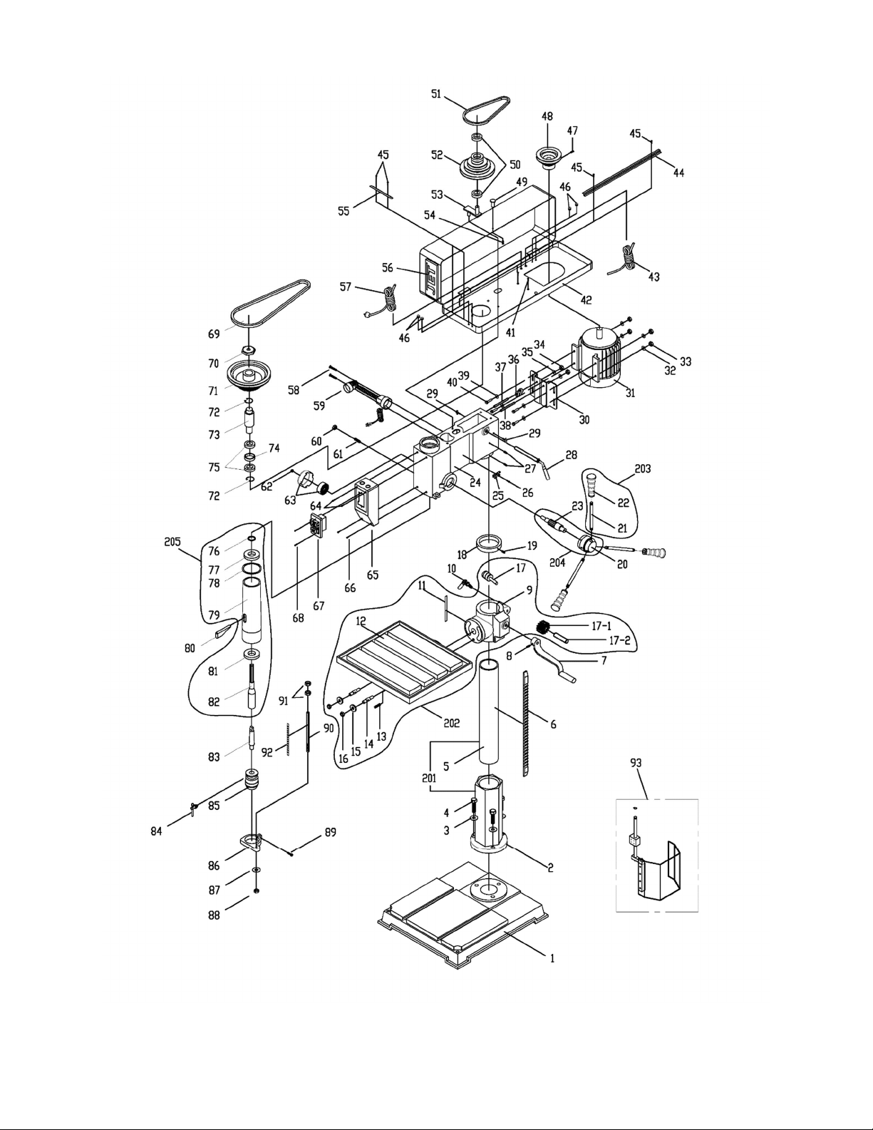
14.2.1 IDP-22 Drill Press – Exploded View
18

14.2.2 IDP-22 Drill Press – Parts List
Index No Part No Description Size Qty
1 ................ IDP22-01 ................... Base ........................................................................ 575 x 500 x 85 .............. 1
201 ............ IDP22-201 ................. Column Assembly (#2,5) ......................................... ...................................... 1
2 ................ IDP22-02 ................... Column Holder ......................................................... ...................................... 1
3 ................ TS-0720111 .............. Spring Washer ......................................................... 1/2" ................................ 3
4 ................ TS-0070051 .............. Hex Cap Screw ........................................................ 1/2" x 2 mm ................... 3
5 ................ IDP22-05 ................... Column .................................................................... Ø92 ............................... 1
6 ................ IDP22-06 ................... Rack ....................................................................... ...................................... 1
7 ................ IDP22-07 ................... Table Crank ............................................................. ...................................... 1
8 ................ TS-0267022 .............. Set Screw ................................................................ 1/4" x 1/4"...................... 1
202 ............ IDP22-202 ................. Table Assembly (#9, 11-16) .................................... ...................................... 1
9 ................ IDP22-09 ................... Table Bracket .......................................................... ...................................... 1
10 .............. IDP22-10 ................... Clamp Bolt .............................................................. 1/2" x 70 mm ................. 1
11 .............. IDP22-11 ................... Tilt Angle Scale ........................................................ ...................................... 1
12 .............. IDP22-12 ................... Work Table .............................................................. 475 x 413 x 41 .............. 1
13 .............. TS-0271031 .............. Set Screw ................................................................ 3/8" x 3/8"...................... 1
14 .............. IDP22-14 ................... Screw ....................................................................... 9/16" x 1/2" x 62 ............ 2
15 .............. TS-0680061 .............. Flat Washer ............................................................. 1/2" x 34 x 5 mm ........... 2
16 .............. TS-0561051 .............. Hex Nut .................................................................... 1/2" ................................ 2
17 .............. IDP22-17 ................... Worm Gear Assembly ............................................. ...................................... 1
17-1 ........... IDP22-17-1 ................ Pinion Gear .............................................................. SC15 ............................. 1
17-2 ........... IDP22-17-2 ................ Shaft ........................................................................ ...................................... 1
18 .............. IDP22-18 ................... Rack Collar .............................................................. Ø92 ............................... 1
19 .............. TS-0267021 .............. Set Screw ................................................................ 1/4" x 1/4"...................... 1
20 .............. IDP22-20 ................... Feed Hub ................................................................. ...................................... 1
203 ............ IDP17-203 ................. Feed Handle Assembly (#21,22) ............................. ...................................... 3
21 .............. IDP22-21 ................... Handle ..................................................................... ...................................... 3
22 .............. IDP22-22 ................... Knob ....................................................................... ...................................... 3
204 ............ IDP22-204 ................. Feed Pinion Assembly (#20,23) .............................. ...................................... 1
23 .............. IDP22-23 ................... Feed Pinion ............................................................. ...................................... 1
24 .............. IDP22-24 ................... Head Casting ........................................................... ...................................... 1
25 .............. IDP22-25 ................... Chuck Key Fixture ................................................... ...................................... 1
26 .............. 5711571 .................... Phillips Pan Head Screw ......................................... 3/16" x 1/4".................... 1
27 .............. TS-0271031 .............. Set Screw ................................................................ 3/8" x 3/8"...................... 2
28 .............. IDP22-27 ................... Tension Adjust Handle ............................................ ...................................... 1
29 .............. IDP22-29 ................... Thumb Screw .......................................................... 3/8” x 32 ........................ 2
30 .............. IDP22-30 ................... Mounting Plate ......................................................... ...................................... 1
31 .............. IDP22-31 ................... Motor ....................................................................... 1-1/2HP 115/230V ........ 1
.................. IDP22-31MF .............. Motor Fan ................................................................ ...................................... 1
.................. IDP22-31MFC ........... Motor Fan Cover (not shown) .................................. ...................................... 1
.................. IDP22-31SC .............. Start Capacitor ......................................................... 400MFD 125VAC .......... 1
.................. IDP22-31RC .............. Run Capacitor .......................................................... 40F 250VAC ............... 1
.................. IDP17-30-JB .............. Junction Box ............................................................ ...................................... 1
.................. IDP17-30-JBC ........... Junction Box Cover ................................................. ...................................... 1
32 .............. TS-0680031 .............. Flat Washer ............................................................. 5/16" x 18 x 1.5 mm ...... 4
33 .............. TS-0561021 .............. Hex Nut .................................................................... 5/16" .............................. 4
34 .............. TS-0561051 .............. Hex Nut .................................................................... 1/2" ................................ 2
35 .............. TS-0680061 .............. Flat Washer ............................................................. 1/2" ................................ 2
36 .............. IDP22-36 ................... Shaft Lever .............................................................. ...................................... 1
37 .............. IDP22-37 ................... Adjusting Bolt B ....................................................... ...................................... 1
38 .............. IDP22-38 ................... Adjusting Bolt A ....................................................... ......
39 .............. TS-0680031 .............. Flat Washer ............................................................. 5/16" x 18 x 1.5 mm ...... 4
40 .............. TS-0051011 .............. Hex Cap Screw ........................................................ 5/16" .............................. 4
41 .............. TS-0207011 .............. Phillips Pan Washer Head Screw ............................ 1/4" x 3/8"...................... 4
42 .............. IDP22-42 ................... Pulley Cover ............................................................ ...................................... 1
43 .............. IDP22-43 ................... Motor Cord ............................................................... 3x14AWG, 300V ........... 1
44 .............. IDP22-44 ................... Hold Down Strip ....................................................... ...................................... 1
45 .............. 5711571 .................... Phillips Pan Head Screw ......................................... 3/16" x 1/4".................... 3
46 .............. IDP22-46 ................... Strain Relief ............................................................. ...................................... 1
47 .............. TS-1523011 .............. Set Screw ................................................................ M6 x 8 ........................... 1
48 .............. IDP22-48 ................... Motor Pulley ............................................................. ...................................... 1
................................ 1
19

Index No Part No Description Size Qty
49 .............. IDP22-49 ................... Knob ....................................................................... ...................................... 1
50 .............. BB-6202 .................... Ball Bearing ............................................................. 6202 .............................. 2
51 .............. VB-A27 ...................... V-Belt ....................................................................... A27 ............................... 1
52 .............. IDP22-52 ................... Center Pulley ........................................................... ...................................... 1
53 .............. IDP22-53 ................... Pivot Bracket ........................................................... ...................................... 1
54 .............. TS-081F031 .............. Socket Head Flat Screw .......................................... 1/4" x 1/2"...................... 1
55 .............. IDP22-55 ................... Hold Down Strip ....................................................... ...................................... 1
56 .............. JET-138 ..................... JET Logo with adhesive .......................................... 138 x 57 mm ................. 1
57 .............. IDP22-57 ................... Power Cord .............................................................. 3x14AWG, 300V ........... 1
58 .............. IDP22-58 ................... Screw ....................................................................... ...................................... 1
59 .............. IDP22-59 ................... Work Lamp .............................................................. ...................................... 1
60 .............. TS-0561021 .............. Hex Nut .................................................................... 5/16" .............................. 1
61 .............. TS-0270091 .............. Set Screw ................................................................ 5/16" x 1"....................... 1
62 .............. TS-0561051 .............. Hex Nylon Lock Nut ................................................. 1/2" ................................ 1
63 .............. IDP22-63 ................... Coil Spring with Cover ............................................. ...................................... 1
64 .............. IDP22-64 ................... Phillips Screw .......................................................... 3/16" x 70 mm ............... 2
65 .............. IDP22-65 ................... Switch Box ............................................................... ...................................... 1
66 .............. IDP22-66 ................... Phillips Pan Head Screw ......................................... 3/16" x 1-1/2" ................ 2
67 .............. IDP17-66 ................... On-Off Switch .......................................................... ...................................... 1
68 .............. IDP22-68 ................... Flat Head Screw ...................................................... 1" x 4 mm ...................... 2
69 .............. VB-A38 ...................... V-Belt ....................................................................... A38 ............................... 1
70 .............. IDP22-70 ................... Nut ........................................................................... ...................................... 1
71 .............. IDP22-71 ................... Spindle Pulley .......................................................... ...................................... 1
72 .............. F006058 .................... External Retaining Ring ........................................... Ø65 mm ........................ 2
73 .............. IDP22-73 ................... Drive Taper .............................................................. ...................................... 1
74 .............. IDP22-74 ................... Ball Spacer .............................................................. ...................................... 1
75 .............. BB-6007 .................... Ball Bearing ............................................................. 6007 .............................. 2
76 .............. IDP22-76 ................... Retaining Ring ......................................................... ...................................... 1
77 .............. BB-6005 .................... Ball Bearing ............................................................. 6005 .............................. 1
78 .............. IDP22-78 ................... Rubber Washer ....................................................... ...................................... 1
205 ............ IDP22-205 ................. Quill Assembly (#76-79, 81,82) ............................... ...................................... 1
79 .............. IDP22-79 ................... Quill ......................................................................... ...................................... 1
80 .............. IDP22-80 ................... Drift Key ................................................................... ...................................... 1
81 .............. BB-6206 .................... Ball Bearing ............................................................. 6206 .............................. 1
82 .............. IDP22-82 ................... Spindle ..................................................................... MT3 ............................... 1
83 .............. 561773 ...................... Morse Taper Arbor................................................... MT3 x JT3 ..................... 1
84 .............. 561708-CK ................ Chuck Key ............................................................... ...................................... 1
85 .............. 561708 ...................... Chuck and Key ........................................................ JT3, 5/8" ........................ 1
86 .............. IDP22-86 ................... Depth Stop Base ..................................................... ...................................... 1
87 .............. TS-0680041 .............. Flat Washer ............................................................. 3/8" ................................ 1
88 .............. TS-0561031 .............. Hex Nut .................................................................... 3/8" ................................ 1
89 .............. TS-0050031 .............. Hex Cap Screw ........................................................ 1/4" x 3/4"...................... 1
90 .............. IDP22-90 ................... Depth Stop Rod ....................................................... ...................................... 1
91 .............. TS-0561071 .............. Hex Nut .................................................................... 5/8" ................................ 2
92 .............. IDP22-92 ................... Scale (mm) .............................................................. ...................................... 1
93 .............. IDP17-92 ................... Spindle Guard Assembly ......................................... ...................................... 1
94 .............. LM000146 ................. Warning Label (not shown) ...................................... ...................................... 1
95 .............. LM000148 ................. ID Label, IDP-22 (not shown) .................................. ...................................... 1
96 .............. LM000150 ................. Spindle Speed Chart (not shown) ............................ ...................................... 1
97 .............. LM000152 ................. Motor Label (not shown) .......................................... ...................................... 1
20

15.0 Electrical Connections for IDP-17, IDP-22
115/230V
21

16.0 Warranty and service
JET warrants every product it sells against manufacturers’ defects. If one of our tools needs service or repair, please
contact Technical Service by calling 1-800-274-6846, 8AM to 5PM CST, Monday through Friday.
Warranty Period
The general warranty lasts for the time period specified in the literature included with your product or on the official
JET branded website.
JET products carry a limited warranty which varies in duration based upon the product. (See chart below)
Accessories carry a limited warranty of one year from the date of receipt.
Consumable items are defined as expendable parts or accessories expected to become inoperable within a
reasonable amount of use and are covered by a 90 day limited warranty against manufacturer’s defects.
Who is Covered
This warranty covers only the initial purchaser of the product from the date of delivery.
What is Covered
This warranty covers any defects in workmanship or materials subject to the limitations stated below. This warranty
does not cover failures due directly or indirectly to misuse, abuse, negligence or accidents, normal wear-and-tear,
improper repair, alterations or lack of maintenance. JET woodworking machinery is designed to be used with Wood.
Use of these machines in the processing of metal, plastics, or other materials outside recommended guidelines may
void the warranty. The exceptions are acrylics and other natural items that are made specifically for wood turning.
Warranty Limitations
Woodworking products with a Five Year Warranty that are used for commercial or industrial purposes default to a
Two Year Warranty. Please contact Technical Service at 1-800-274-6846 for further clarification.
How to Get Technical Support
Please contact Technical Service by calling 1-800-274-6846. Please note that you will be asked to provide proof
of initial purchase when calling. If a product requires further inspection, the Technical Service representative will
explain and assist with any additional action needed. JET has Authorized Service Centers located throughout the
United States. For the name of an Authorized Service Center in your area call 1-800-274-6846 or use the Service
Center Locator on the JET website.
More Information
JET is constantly adding new products. For complete, up-to-date product information, check with your local distributor
or visit the JET website.
How State Law Applies
This warranty gives you specific legal rights, subject to applicable state law.
Limitations on This Warranty
JET LIMITS ALL IMPLIED WARRANTIES TO THE PERIOD OF THE LIMITED WARRANTY FOR EACH PRODUCT.
EXCEPT AS STATED HEREIN, ANY IMPLIED WARRANTIES OF MERCHANTABILITY AND FITNESS FOR A
PARTICULAR PURPOSE ARE EXCLUDED. SOME STATES DO NOT ALLOW LIMITATIONS ON HOW LONG AN
IMPLIED WARRANTY LASTS, SO THE ABOVE LIMITATION MAY NOT APPLY TO YOU.
JET SHALL IN NO EVENT BE LIABLE FOR DEATH, INJURIES TO PERSONS OR PROPERTY, OR FOR
INCIDENTAL, CONTINGENT, SPECIAL, OR CONSEQUENTIAL DAMAGES ARISING FROM THE USE OF OUR
PRODUCTS. SOME STATES DO NOT ALLOW THE EXCLUSION OR LIMITATION OF INCIDENTAL OR
CONSEQUENTIAL DAMAGES, SO THE ABOVE LIMITATION OR EXCLUSION MAY NOT APPLY TO YOU.
JET sells through distributors only. The specifications listed in JET printed materials and on official JET website are
given as general information and are not binding. JET reserves the right to effect at any time, without prior notice,
those alterations to parts, fittings, and accessory equipment which they may deem necessary for any reason
whatsoever. JET
Product Listing with Warranty Period
90 Days – Parts; Consumable items
1 Year – Motors; Machine Accessories
2 Year – Metalworking Machinery; Electric Hoists, Electric Hoist Accessories; Woodworking Machinery used
for industrial or commercial purposes
5 Year – Woodworking Machinery
Limited Lifetime – JET Parallel clamps; VOLT Series Electric Hoists; Manual Hoists; Manual Hoist
Accessories; Shop Tools; Warehouse & Dock products; Hand Tools; Air Tools
NOTE: JET is a division of JPW Industries, Inc. References in this document to JET also apply to JPW Industries,
Inc., or any of its successors in interest to the JET brand.
®
branded products are not sold in Canada by JPW Industries, Inc.
22

This page intentionally left blank.
23

427 New Sanford Road
LaVergne, Tennessee 37086
Phone: 800-274-6848
www.jettools.com
24
 Loading...