

Page 1
Operating Instructions and Parts Manual
Semi-Automatic Band Saw
Model HBS-1321W
WALTER M EIE R (Manufac turing) Inc.
427 New Sanford Road
LaVergne, Tennessee 37086 Part No. M-414471
Ph.: 800-274-6848 Revision G2 01/2012
www.waltermeier.com Copyright © 2012 Walter Meier (Manufacturi ng) Inc .
Page 2
Warranty and Service
W alter Meier (Manufacturing) Inc., warrants every product it sells. If one of our tools needs service or repair, one of
our Authorized Service Centers located throughout the United States can give you quick service. In most cases, any
of these Walter Meier Authorized Service Centers can authorize warranty repair, assist you in obtaining parts, or
perform routine maintenance and major repair on your JET® tools. For the name of an Authorized Service Center in
your area call 1-800-274-6848.
MORE INFORMATION
Walter Meier is consistently adding new products to the line. For complete, up-to-date product information, check with
your local Walter Meier distributor, or visit waltermeier.com.
WARRANTY
JET products carry a limited warranty which varies in duration based upon the product (MW = Metalworking, WW =
Woodworking).
WHAT IS COVERED?
This warranty covers any defects in workmanship or materials subject to the exceptions stated below. Cutting tools,
abrasives and other consumables are excluded from warranty coverage.
WHO IS COVERED?
This warranty covers only the initial purchaser of the product.
WHAT IS THE PERIOD OF COVERAGE?
The general JET warranty lasts for the time period specified in the product literature of each product.
WHAT IS NOT COVERED?
Five Year Warranties do not cover woodworking (WW) products used for commercial, industrial or educational
purposes. Woodworking products with Five Year Warranties that are used for commercial, industrial or education
purposes revert to a One Year Warranty. This warranty does not cover defects due directly or indirectly to misuse,
abuse, negligence or accidents, normal wear-and-tear, improper repair or alterations, or lack of maintenance.
HOW TO GET SERVICE
The product or part must be returned for examination, postage prepaid, to a location designated by us. For the name
of the location nearest you, please call 1-800-274-6848.
You must provide proof of initial purchase date and an explanation of the complaint must accompany the
merchandise. If our inspection discloses a defect, we will repair or replace the product, or refund the purchase price,
at our option. We will return the repaired product or replacement at our expense unless it is determined by us that
there is no defect, or that the defect resulted from causes not within the scope of our warranty in which case we will,
at your direction, dispose of or return the product. In the event you choose to have the product returned, you will be
responsible for the shipping and handling costs of the return.
HOW STATE LAW APPLIES
This warranty gives you specific legal rights; you may also have other rights which vary from state to state.
LIMITATIONS ON THIS WARRANTY
WALTER MEIER (MANUFACTURING) INC., LIMITS ALL IMPLIED WARRANTIES TO THE PERIOD OF THE
LIMITED WARRANTY FOR EACH PRODUCT. EXCEPT AS STATED HEREIN, ANY IMPLIED WARRANTIES OR
MERCHANTABILITY AND FITNESS ARE EXCLUDED. SOME STATES DO NOT ALLOW LIMITATIONS ON HOW
LONG THE IMPLIED WARRANTY LASTS, SO THE ABOVE LIMITATION MAY NOT APPLY TO YOU.
WALTER MEIER SHALL IN NO EVENT BE LIABLE FOR DEATH, INJURIES TO PERSONS OR PROPERTY, OR
FOR INCIDENTAL, CONTINGENT, SPECI AL, OR CONSEQUENTIAL DAMAGES ARISING FROM THE USE OF
OUR PRODUCTS. SOME STATES DO NOT ALLOW THE EXCLUSION OR LIMITATION OF INCIDENTAL OR
CONSEQUENTIAL DAMAGES, SO THE ABOVE LIMITATION OR EXCLUSION MAY NOT APPLY TO YOU.
Walter Meier sells through distributors only. The specifications in Walter Meier catalogs are given as general
information and are not binding. Members of Walter Meier reserve the right to effect at any time, without prior notice,
those alterations to parts, fittings, and accessory equipment which they may deem necessary for any reason
whatsoever. JET® branded produc ts are not sold in Canada by Walter Meier.
2
Page 3

WARNING
• Read and understand th e entire instruction manual befo re at t emptin g assembly or operation.
• All JET bandsaws are design ed and in t end ed for u se by properly trained and experien ced
personnel only. If you are no t familiar with the proper and safe operatio n o f a band saw, do
not use until proper t rain ing and knowledge have been obtained.
• Always wear approved safety glasses/face shields while using this machine.
• Make cert ain t he machine is properly grounded.
• Befor e operating the machine, remov e tie, rings, watches, other jewelry , and roll up sleeves above
the elbows. Remove all loose clothing and confine long hai r . Do NOT wear gloves.
• Keep the floor ar ound the machine clean and free of scrap material, oil and grease.
• Keep machine guar ds in place at all times when the machine is in use. If remov ed f or maintenance
purposes, use ext r eme caution and replace the guards imm ediately.
• Do NOT over reach. Maintain a balanced stance at all times so that y ou do not f all or l ean against
blades or other moving parts.
• Make all m achi ne adjustments or maintenance with t he machine unplugged from the power source.
• Use the right tool. Don't force a tool or attachment to do a job whic h it was not designed for.
• Replace warning labels if they become obscured or r em ov ed.
• Make cert ain t he mot or switc h is i n the OFF position before connecting the machine to the power
supply.
• Give your work undivided attention. Looking around, carrying on a conversation, and "horse-play"
are careless acts that c an r esul t in serious injury.
• Keep visitors a safe distance from the work area.
• Use recommended ac c essories; improper accessories may be hazardous.
• Make a habit of check ing to see that keys and adjusting wrenches are rem ov ed before turning on the
machine.
• Always keep hands and fingers away from the blade when the machine is running.
• Never hand hold the material. Always use the vise and clamp it securely.
• Keep belt guar d, blade guards, and wheel covers in pl ace and in working order.
• Always provide adequate support for long and heav y mater ial.
• Use a sharp blade and keep mac hine clean for best and safest perf ormance.
• Failure to comply with all of these warnings may cause serious i njury.
• Some dust creat ed by power sanding, sa wing, grinding, drilling and other construction activities
contain chemi c als known to cause cancer, birth def ects or ot her r epr oduc tive harm. Some examples
of these chemic als are:
Lead from lead based paint.
Crystalline sil ic a from bricks, cement and other m asonry pr oduc ts.
Arsenic and chromium from chemically treated lum ber .
Your risk of exposure varies, depending on how often you do this type of work. To reduce your
exposure to these chemicals, work in a well-ventilated area and work with approved safety
equipment, such as face or dust masks that are specifically designed to filter out microscopic
particles.
Page 4

Specifications:
Model: HBS-1321W
Stock Number.................................................................................................................... 414471
Capacity:
Round at 90° (in) ................................................................................................. 13” (330 mm)
Round at 45° (in) ........................................................................................... 10-1/2” (268 mm)
Rectangle at 90° (in) ............................... 10” x 21” (254x533 mm) and 13” x 19” (330x483 mm)
Rectangle at 45° (in) ................................................................11-1/2” x 10-1/2” (292x268 mm)
Throat Depth (in) ...................................................................................................... 13” (330 mm)
Blade Size (in) ................................................... 1-1/4” x 0.042” x 161-1/2” (31.75x1.07x4102 mm)
Blade Wheel Diameter (in) ........................................................................................ 18” (457 mm)
Blade Speeds (SFP M) ........................................................................................................ 80-260
Floor Space Requir ed (i n) .................................................................84” x 32-1/2” (2134x826 mm)
Bed Height (in) ......................................................................................................... 32” (813 mm)
Motor .................................................................................. 3 HP, 3 PH, 230/460 (Prewired 230V)
Coolant Motor ..................................................................................................................... 1/6 HP
Net Weight (approx.)........................................................................................... 1,276 lb (579 kg)
Table of Contents
Warranty ..................................................................................................................................... 2
Warnings ..................................................................................................................................... 3
Specifica tions .............................................................................................................................. 4
Table of Contents ........................................................................................................................ 4
Uncrating and Cleanup ................................................................................................................ 5
Installation ................................................................................................................................... 5
Assembly .................................................................................................................................5-6
Electric al Connec tions ................................................................................................................. 6
Controls ....................................................................................................................................6-7
Prior To Ope r a t io n ....................................................................................................................... 7
Adjusting Vise Squar e t o Bl ade .................................................................................................... 8
Adjustin g Vise for Miter Cuts ........................................................................................................ 8
Positioning Vise ........................................................................................................................... 8
Changing Blade Speeds .............................................................................................................. 9
Semi Automatic Arm .................................................................................................................... 9
Automatic Shut Off ...................................................................................................................... 9
Adjusting Feed Rate .................................................................................................................... 9
Changing Blades ....................................................................................................................... 10
Guide Roller Adjustment ............................................................................................................ 11
Blade Guide Adjustm ent ............................................................................................................ 11
Blade Tracking Adjustment ........................................................................................................ 12
Lubrication & Gear box .......................................................................................................... 12-13
Hydraulic Pump ......................................................................................................................... 13
Coolant Pump............................................................................................................................ 13
Replacing Vari able Speed Belt .................................................................................................. 13
Bed and Base Assembly Break down & Parts List .................................................................. 14-17
Arm Assembly Breakdown & Parts List ................................................................................. 18-22
Gearbox Assembly Breakdown & Parts List ............................................................................... 22
Wiring Diagram and Symbols ................................................................................................ 23-24
The specificati ons i n this manual are given as general information and are not binding. W alter Meier
(Manufactur ing) Inc., reserves the ri ght t o eff ect, at any tim e and without pri or notice, changes or
alterations to par ts, fittings, and accessory equipment deemed necessary for any reason whatsoever.
4
Page 5
Uncrating and Cleanup
1. Read and understand the entire manual
before attempting setup or operation.
2. Finish uncrating the saw and inspect for
damage. If any damage has occurr ed,
contact your local distributor.
3. Remove all bolts att ac hing m ac hine to
shipping base.
4. Leave packing material between vice
clamps and saw head intact until bandsaw
has been lifted to its final position.
5. Clean all rust protected surfaces with
kerosene or diesel oi l t o remov e pr otective
coating. Do not use gasoline, paint thinner,
mineral spirits, etc. These may damage
painted surf ac es.
6. Lubricate all slideways with a light film of
Mobil DTE® Oi l Heavy Medium.
Installation
For best perform anc e, t he bandsa w shoul d be
located on a solid and level foundation. Allow
room for servicing and for moving large stock
around the bandsaw when deci ding a location
for the machine.
1. Using lifting str aps of adequate lifting
capacity, that are isolated from the
bandsaw's finished surfaces, lift mac hine
and place in desired l oc ation. See Figure 1
for strap placement.
2. Install four lev eling bolts with lock nuts on
both sides of the base.
3. Place a level on the bed surface and check
side to side and front to bac k.
4. Adjust leveling screws until machine is level
in both directi ons and tighten locking nuts.
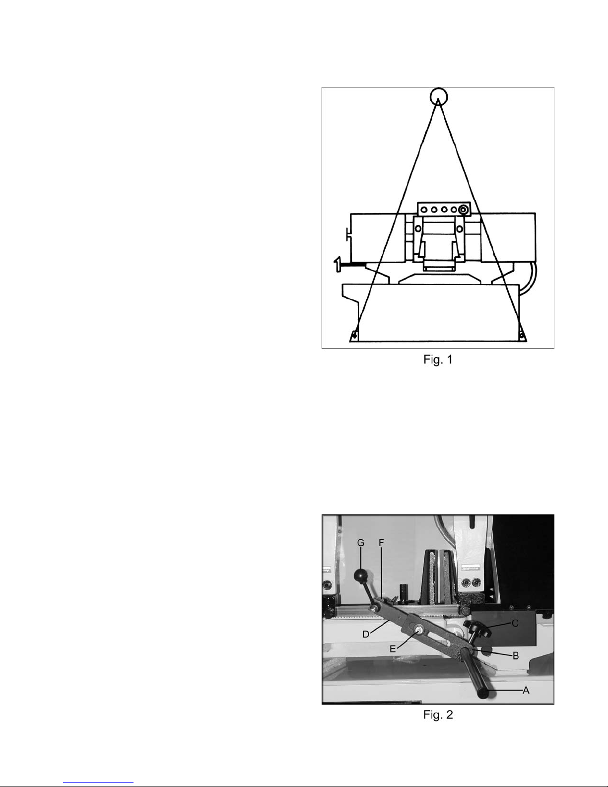
Assembly
1. Insert stop rod (A, Fig. 2) i nto t he base
below the vise. Plac e stop br ac k et (B, Fig.
2) onto stop rod and tighten loc k k nob ( C,
Fig. 2). Attach the connec ting plate (D, Fig.
2) to stop bracket with hex c ap bolt and
washer (E, Fig. 2), and tighten. Attach the
work stop (F, Fig. 2) t o the connec ting plate
with lock handle (G, Fi g. 2), and tighten.
5
Page 6
2. Slide the tensioni ng handle (A, Fig.3) onto
the shaft and tighten the hex socket set
screw.
Electrical Connections
WARNING
All electrical connections must be done by a
qualified el ect rician! Failure to comply may
result in serious injury!
WARNING
Disconnect mach in e f rom the power sou rce
before changing any volt age components!
Failure to compl y may cause seri ou s in ju ry!
The HBS-1321W bandsaw is rated at 230/460V,
3Ph. and is prewired 230 volt from the factory.
Confirm power source available at the saw's
location is the sam e as the saw is wired. T o
switch the HBS-1321W from 230V to 460V, t he
following items will have to be changed:
Bandsaw must always be properly grounded.
• Main Motor: Follow diagram insi de junction
box cover.
• Coolant Pump: Follow diagram inside
junction box cov er.
• Control Transformer: Open electrical
panel on rear of base and switch only the
one 230V primary wire on t r ansformer to the
460V position.
• Hydraulic Pump: Remove access panel
and follow diagram inside junction box
cover.
Controls (figure 4)
A. Power Indicator Li gh t : Lit whenev er
machine has power.
B. Start Button: Depress to start bandsa w.
Will not work if emergenc y butt on is
depressed.
C. Stop Button: Depress to stop bandsaw.
D. Emergency Stop Button: Depress to
immediately stop all m ac hine functions.
E. Arm Up Button: Depress to raise arm.
6
Page 7
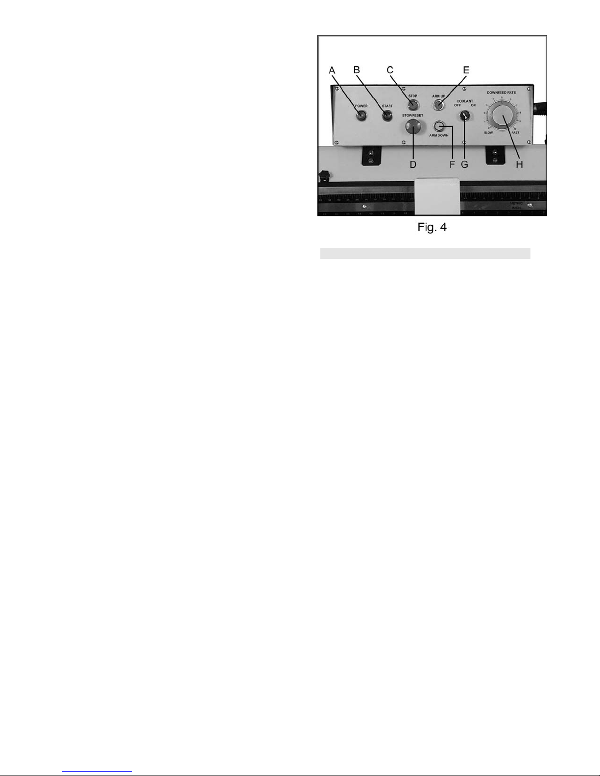
F. Arm Down Button: Depress to lower arm.
G. Coolant Switch: Turn arrow to ON starting
flow of coolant. Turn arr ow to OFF stopping
flow of coolant. Blade m ust be ci r c ulating
for coolant pump to work.
H. Downfeed Rate Knob: Turn clockwise to
increase down feed r ate. Tur n counter clockwise to decr ease do wn feed rate. See
adjusting feed r ate page 9.
Prior to Operation
1. All JET bandsaws are designed and
intended for use by proper ly tr ained and
experienced personnel only. If you are not
familiar with the proper and safe operation of
a bandsaw, do not use until pr oper tr aining
and knowledge have been obtained.
2. Check blade toot h dir ection matches
diagram on blade guides.
3. Check to see that blade i s proper ly seated
on wheels after appl yi ng c or r ect tension
(approximately 25,000 lbs.).
4. Check blade guides for pr oper adjust ments.
See guide adjustm ent s, page 11.
5. Position sliding blade guide arms as close to
workpiece as possible.
6. Select proper speed and f eed rate for
material being c ut. See speed select ion
chart found in the encl osed "Guide to
Bandsawing" booklet supplied with thi s saw.
7. Material to be cut must be securely held in
the vise. See vise adjustment page 8.
8. Check to see that coolant lev el is adequat e
and turn on coolant pump if material to be
cut requires it. S ee cool ant pump page 13.
9. Do not start cut on a sharp edge.
7
Page 8
WARNING
Disconnect mach in e f rom the power sou rce
before adju sting or changi ng vise position!
Failure to compl y may cause seri ou s in ju ry!
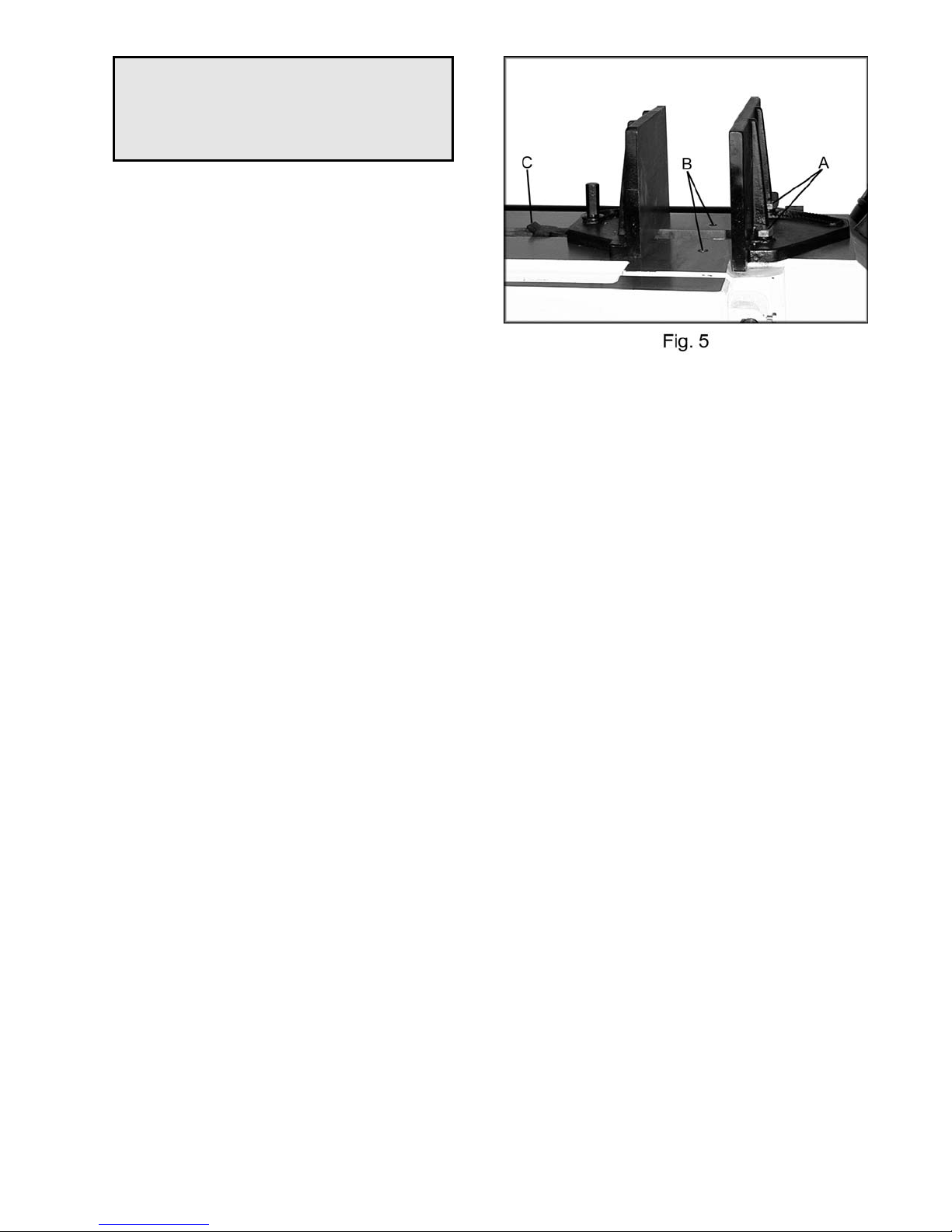
Adjusting Vise Square to the Blade
Position A
1. Place a machinist' s square on the bed
against the blade and the vise. The square
should lie along t he entire length of the vise
and blade without a gap.
2. If adjustment is necessary, loosen bolts (A,
Fig. 5) holding the vise and adjust vise so
square lines up properl y . Tighten bolts.
3. You may want to perform a test cut. Cut off
the end of the stock. Make anot her cut so
that you have an accurat e sect ion to
measure. Measure thic k ness wit h c alipers.
Adjusting Vise for Mite r Cuts
Position B
1. Move the vi se into the second set of
threaded holes (B, Fig. 5) by removing hex
cap bolts (A, Fig. 5).
2. When angle has been set ti ght en bolts.
3. Adjust other jaw.
4. There is an angle label on t he backsi de of
the bed. This is for refer enc e only. Chec k
angles with a machi nist’s prot r ac tor.
For your own safety: only use position B for
miter cuts. Vise square to the blade, in position
B would expose more of the blade, ri ght of the
vise, than is necessary for the cut.
Positioning Vise
To position the m ov eable v ise:
1. Pull up on the rack block (C, Fig. 5).
2. Move vise to desired l oc ation by sliding
along bed.
3. Tighten vise by turning handwheel, found at
the left end of the bed, clock wise.
4. Loosen vise by turning handwheel counter-
clockwise so you can pull up on the rack
block.
8
Page 9

Changing Blade Speeds
Adjust the variable blade speed only while the
machine is running. The dial (A, Fig. 6) sticking
out of the belt cover (right si de) controls the
variable speeds between 66 F P M to 264 F PM.
Semi-Automatic Arm
Preset the height , whic h t he arm stops when i t
raises automati c ally. The height the arm raises
depends upon the piece you want t o c ut. The
limit switch is l owered or raised by loosening a
locking handle ( A, Fig. 7). Tight en the locking
handle when the limit switc h has been properly
adjusted.
Automatic S h u t-Off
The blade will stop aft er the m aterial has been
cut, and the arm reaches it s l owest position.
The arm will automatically rise to the preset
height.
Adjusting Feed Rate
Rate of downfeed is adjusted by t ur ning the
downfeed knob on the contr ol panel. Rate of
feed is important to bandsa w performance;
excessiv e pressure may break the blade or stall
the saw. Insufficient pressure rapidly dulls the
blade.
Material c hips or shavi ngs are t he best indicator
of proper speed and downfeed. The ideal chip
is thin, tightl y curled, and warm to the touch.
Chips that range fr om gol den brown to black
indicate excessive force. Blue chips indicat e
extreme heat from too high a band speed, which
will shorten blade life. Thin or powdered chips
indicate insufficient downfeed rate.
9
Page 10

Changing Blades
WARNING
Disconnect mach in e f rom the power sou rce
before making any adjust ments or repairs!
Failure to compl y may resul t in seri ou s
injury!
1. Raise the saw arm approximately 6".
2. Disconnect machine from power source.
3. Open both wheel covers and clean chips out
of both wheel housings. Loosen l oc k knobs
and remove upper and lower bl ade guar ds.
4. Release blade tension by turning blade
tensioning handwheel ( A , Fi g. 8) c ount er clockwise until blade is free.
5. Loosen lock handl e and sli de left blade
guide arm (B, Fig. 8) to the right as far as
possible.
6. Remove old blade fr om both wheels and out
of each blade guide. Caution: Even dull
blades are sharp to the skin! Use ext r a
caution handli ng bandsa w blades!
7. Install a new blade making sure teeth are
pointed downward in t he pr oper c utt ing
direction.
8. Position blade on wheels and tighten just
enough to hold blade on wheels. Make sure
back of blade rests li ghtly against the wheel
flange of both wheels. T wist blade slightly to
allow it to slip into guides.
9. Tension blade to appr oximately 25,000 lbs.
Blade tension is indic ated on the tension
wheel shaft housing (left side).
10. Install all guards, cl ose covers and fasten
securely. Connect machine to power and
run freely for approximately two minutes.
11. Turn power of f and re-check blade tension
and wire brush adjustment. If further
adjustment i s necessary, disconnect saw
from power source, make adjustments,
and re-connect to power.
10
Page 11

Guide Roller Adjustment
The bearings come pre- adjusted from the
factory. If adjustm ent is needed follow the below
steps:
1. Disconnect mach ine from the power
source.
2. Loosen two hex socket cap screws (A, Fig. 9).
3. Move guide seat (B, Fi g. 9) up or down until
an approximat e cl ear anc e of .003" between
blade and bearing is obtained, (C, Fig. 9).
4. Tighten two hex socket cap screws (A, Fig. 9).
5. Adjust the eccentr ic bearings (A, Fig. 10) by
loosening hex sock et cap screw (B, Fig. 10)
about one full turn.
6. With a 19mm wrench turn hex nut (C, Fig.
10) until the ball beari ngs are approximately
.003”. Note: Do not pinch the blade.
7. Tighten the hex socket cap screw (B, Fig.
10) while holding t he hex nut ( C, Fig. 10) in
place.
8. Repeat for other blade guide assembly.
9. Connect machine to power source.
Blade Guide Adjustment
The blade guides com e pr e- adjusted from the
factory. If adjustm ent is needed follow the below
steps:
1. Disconnect mach ine from the power
source.
2. Adjust spring l oaded blade guide (A, Fig. 11)
by loosening or tightening the guide
adjustment screw (B, Fig. 11).
3. The blade guide should pl ac e a light
pressure on the blade.
4. Connect machi ne to the power source.
11
Page 12

Blade Tracking Adjustment
Since tracking c an only be adjusted while
machine is running, it is suggested that this
adjustment be acc om plished by qualified
personnel that ar e famil iar with this type of
adjustment and the danger s associated with it.
Blade tracki ng has been set at t he factory and
should require no adj ustment. If a tracking
problem occur s, adjust the machine as follows:
WARNING
Tracking adju st ment is done with the wheel
covers open to observe the blade. Use
extreme cautio n so as not to come into
contact with the blade!
1. Raise saw arm to its highest position.
2. Locate tracking adjustment plate on the
backside of the idle wheel.
3. Loosen the three bolts (A , Fig. 12) located
on the top of the tracking nut s.
4. Tracking adj ustm ent is accomplished by
either loosening or tightening three adj usting
nuts (B, Fig. 12).
5. Tracking i s set properly when the back of
the blade lightly touches the wheel flange.
Note: over-tracking (allowing blade back to
rub hard against wheel flange) will damage
the blade wheels and blade.
6. Tighten locki ng bolts (A) once proper
tracking is com pleted.
Lubrication and Gearbox
All ball bearings are permanently lubric ated and
sealed. They requir e no f urt her lubr ic ation.
The gearbox lubri c ant shoul d be c hanged after
the first 3 months of operation. Use Mobil SHC
634, or equivalent . Change lubricant from then
on every year.
To check level of gear box lubr ic ant, place arm
in down position and all ow a few mi nutes to
pass so that oil drains down. Check level in
sight glass on side of gear casing. Correct level
is the dot in the middle of si ght gl ass.
12
Page 13

To change gear box lubricant:
1. Disconnect machine from the power
source.
2. Remove drain plug and all ow l ubr ic ant to
drain complet ely . T he drai n plug is l oc ated
on lower front of gear case under right
wheel cover. Remove drain plug with a hex
wrench.
3. Reinstall drain plug.
4. Remove filler cap and fill gear box with Mobil
SHC 634 until level reac hes dot in mi ddle of
sight glass.
5. Reinstall filler cap.
6. Use Mobil DTE® Oil Heavy Medium to
lubricate all ot her m ov ing parts as needed.
Hydraulic Pump
If you need to add hydrauli c fluid to the tank
remove cap (A, Fig. 13). Add Mobil DTE ® 24
until the black ball floats to the full position.
Coolant Pump
The coolant tank shoul d be filled with 6 gallons
of a cutting coolant. Fill by pouri ng c oolant into
the chip tray. Add cool ant i n the same manner
when coolant is low. To drain coolant remove
hex cap screw (A, Fig. 14). Follow all coolant
manufacturer ’s i nstr uc tions for safety, mixi ng
disposal, etc.
The spray nozzle (B, Fig. 14) enabl es the user
to wash chips out of the way. Ther e are thr ee
ball valves that control the coolant distri buti on to
the spray nozzle and eac h blade guide.
Replacing the Variable Speed Belt
Disconnect the mac hine from the power source.
Take the belt cover off by remov ing the knob
and washer. Loosen tension on the belt by
turning the variable speed dial (A, Fig. 15) to the
lowest setting. This will allow you to remove the
belt (B, Fig. 15). When installing the new belt
turn the pulley by hand while increasing variable
speed dial setti ng. Aft er runni ng the machine
additional adjustment of the variable speed di al
may be needed.
13
Page 14

Bed and Base Assembly
14
Page 15

Parts List for the JET HBS-1321W Bandsaw
Bed and Base Assembly
Index Part
No. No. Description Size Qty.
1 .......... 1321W-01 ................................. Base ......................................... ............................................... 1
2 .......... TS-1492061 .............................. Hex Cap Bolt ............................. M12x65 ................................... 4
3 .......... TS-1540081 .............................. Hex Nut..................................... M12 ........................................ 4
4 .......... 1321W-04 ................................. Coolant Pump ........................... 1 /6HP ..................................... 1
4-1....... 1321W-04-1 .............................. Cross Point Screw .................... M6x16 ..................................... 2
4-2....... 1321W-04-2 .............................. Spring Washer .......................... M6 .......................................... 2
4-3....... 1321W-04-3 .............................. Flat Washer .............................. M6 .......................................... 2
5 .......... TS-1524041 .............................. Set Screw ................................. M8x16 ..................................... 2
6 .......... 1321W-06 ................................. Coolant Tank Cover .................. ............................................... 1
6-1....... TS-1550041 .............................. Washe r ..................................... M6 .......................................... 1
6-2....... TS-1503031 .............................. Hex Socket Cap Screw ............. M6x12 ..................................... 1
6-3....... TS-1551041 .............................. Spring Washer .......................... M6 .......................................... 1
7 .......... 1321W-07 ................................. Bed ........................................... ............................................... 1
7-1....... 1321W-07-1 .............................. Hex Cap Bolt ............................. M12x50 ................................... 4
7-2....... 1321W-07-2 .............................. Spring Washer .......................... M12 ........................................ 4
8 .......... 1321W-08 ................................. Connector ................................. ............................................... 1
8-1....... 1321W-08-1 .............................. Hos e Fitting............................... ............................................... 2
8-2....... 1321W-08-2 .............................. Hos e Clamp .............................. ............................................... 6
8-3....... 1321W-08-3 .............................. Hos e ......................................... 3/8”x1200 ................................ 1
8-4....... 1321W-08-4 .............................. On/Off Valve ............................. ............................................... 3
8-5....... 1321W-08-5 .............................. Hos e ......................................... 3/8”x2800 ................................ 1
8-6....... 1321W-08-6 .............................. Hos e Fitting............................... ............................................... 1
8-7....... 1321W-08-7 .............................. Coola nt Nozzle ......................... ............................................... 1
8-8....... 1321W-08-8 .............................. Connector ................................. ............................................... 1
8-9....... 1321W-08-9 .............................. Fitting ........................................ ............................................... 1
9 .......... 1321W-09 ................................. Coolant Gauge .......................... ............................................... 1
9-1....... TS-1491041 .............................. Pan Head Screw ....................... M10x30 ................................... 2
9-2....... TS-1550071 .............................. Washe r ..................................... M10 ........................................ 2
9-3....... TS-1540071 .............................. Hex Nut..................................... M10 ........................................ 2
10 ........ 1321W-10 ................................. Drain Plug ................................. ............................................... 1
11 ........ 1321W-11 ................................. Front Door w/Latch .................... ............................................... 1
12 ........ 1321W-12 ................................. Hinge Pin .................................. ............................................... 2
13 ........ 1321W-13 ................................. Panel Cover .............................. ............................................... 1
13-1 ..... 1321W-13-1 .............................. Round Cross Cap Screw ........... M6x8 ....................................... 4
14 ........ 1321W-14 ................................. Electr ical Panel Plate ................ ............................................... 1
14-1 ..... 1321W-14-1 .............................. Knob ......................................... ............................................... 1
14-2 ..... 1321W-14-2 .............................. Hinge Pin .................................. ............................................... 2
14-3 ..... 1321W-14-3 .............................. Hex Nut..................................... M6 .......................................... 1
15 ........ 1321W-15 ................................. Lock Knob ................................. ............................................... 1
16 ........ 1321W-16 ................................. Stop Bracket ............................. ............................................... 1
16-1 ..... 1321W-16-1 .............................. Connecting Plate ....................... ............................................... 1
16-2 ..... 1321W-16-2 .............................. Lock Washe r ............................. ............................................... 1
16-3 ..... 1321W-16-3 .............................. Hex Cap Bolt ............................. ............................................... 1
17 ........ 1321W-17 ................................. Stop Rod................................... ............................................... 1
18 ........ 1321W-18 ................................. Lock Handle .............................. ............................................... 1
19 ........ 1321W-19 ................................. Work Stop ................................. ............................................... 1
20 ........ 1321W-20 ................................. Lead Screw Seat ....................... ............................................... 1
20-1 ..... TS-1504061 .............................. Hex Socket Cap Screw ............. M8x30 ..................................... 2
20-2 ..... TS-1551081 .............................. Spring Washer .......................... M8 .......................................... 2
20-3 ..... TS-1550061 .............................. Washe r ..................................... M8 .......................................... 2
15
Page 16

21 ........ 1321W-21 ................................. Handle Wheel Assembly ........... ............................................... 1
21-1 ..... TS-0270031 .............................. Set Screw ................................. 5/16"x3 /8" ............................... 2
21-2 ..... 1321W-21-2 .............................. Handle ...................................... ............................................... 1
22 ........ 1321W-22 ................................. Rack ......................................... ............................................... 1
23 ........ 1321W-23 ................................. Lead Screw Seat ....................... ............................................... 1
23-2 ..... TS-1504041 .............................. Hex Socket Cap Screw ............. M8x20 ..................................... 2
24 ........ 1321W-24 ................................. Lead Screw ............................... ............................................... 1
24-1 ..... 1321W-24-1 .............................. Key ........................................... ............................................... 1
25 ........ 1321W-25 ................................. Slide Bracke t ............................. ............................................... 1
26 ........ 1321W-26 ................................. Vise Jaw - Left .......................... ............................................... 1
26-1 ..... TS-1492041 .............................. Hex Cap Bolt ............................. M12x40 ................................... 1
26-2 ..... 1321W-26-2 .............................. Lockin g Bolt .............................. M12x45 ................................... 1
26-3 ..... TS-1551081 .............................. Spring Washer .......................... M12 ........................................ 2
26-4 ..... TS-1550061 .............................. Washe r ..................................... M12x35x5W ............................ 1
27 ........ 1321W-27 ................................. Rack Block ................................ ............................................... 1
28 ........ TS-1523021 .............................. Set Screw ................................. M6x8....................................... 1
29 ........ 1321W-29 ................................. Pin ............................................ ........................................... .... 1
30 ........ 1321W-30 ................................. Needle Bearing ......................... CB3020 .................................. 2
31 ........ 1321W-31 ................................. Vise Jaw - Right ........................ ............................................... 1
31-1 ..... 1321W-31-1 .............................. Hex Cap Bolt ............................. M16x50 ................................... 1
31-2 .....
1321W-31-2 .............................. Hex Cap Bolt ............................. M16x40 ................................... 1
31-3 ..... 1321W-31-3 .............................. Spring Washer .......................... M16 ........................................ 2
31-4 ..... 1321W-31-4 .............................. Washe r ..................................... M16x35x5W ............................ 1
32 ........ 1321W-32 ................................. Pivot Shaft ................................ ............................................... 1
32-1 ..... TS-1492001 .............................. Hex Cap Bolt ............................. M12x20 ................................... 2
32-2 ..... TS-1550081 .............................. Washe r ..................................... M12 ........................................ 2
33 ........ 1321W-33 ................................. Pivot Bracke t ............................. ............................................... 1
33-1 ..... 1321W-33-1 .............................. Space r ...................................... ............................................... 1
34 ........ 1321W-34 ................................. Spring ....................................... ............................................... 1
35 ........ 1321W-35 ................................. Support Bracket Seat ................ ............................................... 1
36 ........ 1321W-36 ................................. Pivot Support Shaft ................... ............................................... 1
36-1 ..... 1321W-36-1 .............................. C-Clip ....................................... S22 ......................................... 1
37 ........ 1321W-37 ................................. Motor ........................................ 3HP, 3Ph ................................ 1
37-1 ..... 1321W-37-1 .............................. Key ........................................... 8x7 x50 .................................... 1
38 ........ TS-1550041 .............................. Flat Washer .............................. M6 .......................................... 2
39 ........ 1321W-39 ................................. Hex Cap Bolt ............................. M10x55 ................................... 4
39-1 ..... TS-1550071 .............................. Flat Washer .............................. M10 ........................................ 4
39-2 ..... TS-1541071 .............................. Spring Washer .......................... M10 ........................................ 4
39-3 ..... TS-1540071 .............................. Hex Nut..................................... M10 ........................................ 4
40 ........ TS-1492051 .............................. Hex Cap Bolt ............................. M12x50 ................................... 3
40-1 ..... TS-1551081 .............................. Spring Washer .......................... M12 ........................................ 3
40-2 ..... TS-1550081 .............................. Washe r ..................................... M12 ........................................ 3
41 ........ 1321W-41 ................................. Switch Mounting Pl ate ............... ............................................... 1
42 ........ TS-1551041 .............................. Spring Washer .......................... M6 .......................................... 2
43 ........ TS-1482021 .............................. Hex Cap Bolt ............................. M6x12 ..................................... 2
44 ........ 1321W-44 ................................. Cross Point Screw .................... M5x35 ..................................... 8
44-1 ..... 1321W-44-1 .............................. Spring Washer .......................... M5 .......................................... 8
45 ........ 1321W-45 ................................. Limit Switch ............................... 5101 ....................................... 1
45-1 ..... 1321W-45-1 .............................. Roller Limit Switch .................... 5102 ....................................... 1
46 ........ 1321W-46 ................................. Adjus ting Bracket ...................... ............................................... 1
46-1 ..... 1321W-46-1 .............................. Scale Plate ............................... ............................................... 1
46-2 ..... 1321W-46-2 .............................. Rivet ......................................... ............................................... 2
47 ........ 1321W-47 ................................. Cylinder Support Rod ................ ............................................... 1
47-1 ..... 1321W-47-1 .............................. C-Clip ....................................... S32 ......................................... 2
47-2 ..... 1321W-47-2 .............................. C-Clip ....................................... S28 ......................................... 1
48 ........ 1321W-48 ................................. Cylinder Cover .......................... ............................................... 1
49 ........ 1321W-49 ................................. Spring ....................................... ............................................... 1
16
Page 17

50 ........ 1321W-50 ................................. Retain ing Pin ............................ ............................................... 1
51 ........ 1321W-51 ................................. Cylinder Assembly .................... ............................................... 1
51-1 ..... 1321W-51-1 .............................. Holde r ....................................... ............................................... 1
52 ........ 1321W-52 ................................. Cylinder Pin .............................. ............................................... 1
53 ........ 1321W-53 ................................. Top Mounting Plate ................... ............................................... 1
54 ........ TS-1492031 .............................. Hex Cap Bolt ............................. M12x35 ................................... 2
55 ........ TS-1551081 .............................. Spring Washer .......................... M12 ........................................ 2
56 ........ 1321W-56 ................................. Plate ......................................... ............................................... 1
56-1 ..... TS-1482021 .............................. Hex Cap Bolt ............................. M6x12 ..................................... 2
56-2 ..... TS-1551041 .............................. Spring Washer .......................... M6 .......................................... 2
56-3 ..... TS-1550041 .............................. Flat Washer .............................. M6 .......................................... 2
57 ........ 1321W-57 ................................. Switch Mounting Pl ate ............... ............................................... 1
58 ........ TS-1503011 .............................. Hex Socket Cap Screw ............. M6 x8....................................... 2
59 ........ TS-1504051 .............................. Hex Socket Cap Screw ............. M8x25 ..................................... 6
60 ........ TS-1551081 .............................. Spring Washer .......................... M8 .......................................... 2
61 ........ 1321W-61 ................................. Handle ...................................... ............................................... 1
61-1 ..... TS-1550071 .............................. Washe r ..................................... M10 ........................................ 1
62 ........ 1321W-62 ................................. Hydra ulic Pump Motor ............... ............................................... 1
62-1 ..... 1321W-62-1 .............................. Pump ........................................ ............................................... 1
62-2 ..... 1321W-62-2 .............................. Solenoid Valve .......................... ............................................... 1
62-3 ..... 1321W-62-3 .............................. Hydra ulic Fill Cap ...................... ............................................... 1
63 ........ 1321W-HPCA ........................... Hydraulic Pump Complete Assembly ......................................... 1
64 ........ 1321W-64
................................. Scale ........................................ ............................................... 1
65 ........ 1321W-65 ................................. Rivet ......................................... ............................................... 2
66 ........ TS-1503031 .............................. Hex Socket Cap Screw ............. M6x12 ..................................... 2
67 ........ 1321W-67 ................................. Plate ......................................... ............................................... 2
68 ........ 1321W-68 ................................. Roller Seat ................................ ............................................... 2
68-1 ..... TS-1525021 .............................. Set Screw ................................. M10x12 ................................... 2
69 ........ 1321W-69 ................................. Support Roller ........................... ............................................... 2
69-1 ..... BB6004ZZ ................................ Ball Bearin g .............................. 6004ZZ ................................... 2
70 ........ 1321W-70 ................................. Rod ........................................... ............................................... 1
71 ........ 1321W-71 ................................. Knob ......................................... ............................................... 2
72 ........ TS-1523021 .............................. Set Screw ................................. M6x8....................................... 2
73 ........ 1321W-73 ................................. Term inal Strip ........................... ............................................... 2
74 ........ 1321W-74 ................................. Magnetic Switch (w/Overload) ... ............................................... 1
74-1 ..... 1321W-74-1 .............................. Magnetic Switch ........................ ............................................... 1
74-2 ..... 1321W-74-2 .............................. Magnetic Switch ........................ ............................................... 1
75 ........ 1321W-75 ................................. Relay ........................................ ............................................... 1
75-1 ..... 1321W-75-1 .............................. Relay ........................................ ............................................... 1
76 ........ 1321W-76 ................................. Trans former .............................. ............................................... 1
77 ........ 1321W-77 ................................. Fuse Case ................................ ............................................... 1
77-1 ..... 1321W-77-1 .............................. Fuse (3A) .................................. ............................................... 2
17
Page 18

Arm Assembl y
18
Page 19

Arm Assembl y
Index Part
No. No. Description Size Qty.
8-1....... 1321W-08-1 .............................. Hos e Fitting............................... ............................................... 2
8-2....... 1321W-08-2 .............................. Hos e Clamp .............................. ............................................... 6
8-4....... 1321W-08-4 .............................. On/Off Valve ............................. ............................................... 3
80 ........ 1321W-80 ................................. Blade Wheel Cover - R.............. ............................................... 1
80-1 ..... 1321W-80-1 .............................. Hinge Pin .................................. ............................................... 4
81 ........ 1321W-81 ................................. Brus h Cover .............................. ............................................... 1
81-1 ..... TS-1482021 .............................. Hex Cap Bolt ............................. M6x12 ..................................... 2
81-2 ..... TS-1551041 .............................. Spring Washer .......................... M6 .......................................... 2
81-3 ..... TS-1550041 .............................. Flat Washer .............................. M6 .......................................... 2
81-4 ..... TS-1540041 .............................. Nut ............................................ M6 .......................................... 2
82 ........ 1321W-82 ................................. Handle ...................................... ............................................... 2
82-1 ..... 1321W-82-1 .............................. Cross Point Screw .................... M6x16 ..................................... 4
82-2 ..... 1321W-82-2 .............................. Washe r ..................................... M6 .......................................... 4
83 ........ 1321W-83 ................................. Blade Wheel Cover - L .............. ............................................... 1
84 ........ 1321W-84 ................................. Drive Wheel .............................. ............................................... 1
84-1 ..... 1321W-84-1 .............................. Hex Cap Bolt ............................. M12x20 ................................... 1
84-2 ..... 1321W-84-2 .............................. Washe r ..................................... M12 ........................................ 1
85 ........ 1321W-85 ................................. Saw Blade ................................ 1 - 1 /4 ” x .042” x 161-1/2” .......... 1
86 ........ 1321W-86 ................................. Knob ......................................... ............................................... 8
87 ........ TS-1491041 .............................. Hex Cap Bolt ............................. M10x30 ................................... 4
88 ........ TS-1551071 .............................. Spring Washer .......................... M10 ........................................ 4
89 ........ TS-1492031 .............................. Hex Cap Bolt ............................. M12x35 ................................... 4
90 ........ TS-
91 ........ 1321W-91 ................................. Blade Guard.............................. ............................................... 1
92 ........ 1321W-92 ................................. Blade Wheel Box Assembly ...... ............................................... 1
93 ........ 1321W-93 ................................. Connector ................................. ............................................... 1
93-1 ..... 1321W-93-1 .............................. Hex Socket Cap Screw ............. M6x20 ..................................... 2
93-2 ..... 1321W-93-2 .............................. Hos e ......................................... ............................................... 1
93-3 ..... 1321W-93-3 .............................. Hos e ......................................... ............................................... 1
94 ........ 1321W-94 ................................. Gear Box Assembly .................. ............................................... 1
94-1 ..... 1321W-94-1 .............................. Key ........................................... 12 x8x32 .................................. 1
94-2 ..... 1321W-94-2 .............................. Key ........................................... 7x7 x40 .................................... 1
94-3 ..... TS-1525041 .............................. Set Screw ................................. M10x12 ................................... 2
95 ........ 1321W-95 ................................. Plate ......................................... ............................................... 1
95-1 ..... TS-1482021 .............................. Hex Cap Bolt ............................. M6x12 ..................................... 2
95-2 ..... TS-1551041 .............................. Spring Washer .......................... M6 .......................................... 2
95-3 ..... TS-1550041 .............................. Washe r ..................................... M6 .......................................... 2
96 ........ 1321W-96 ................................. Pulley Cover ............................. ............................................... 1
97 ........ 1321W-97 ................................. Input Pulley ............................... ............................................... 1
98 ........ 1321W-98 ................................. Belt ........................................... 1922V443 ............................... 1
99 ........ 1321W-99 ................................. Output Pulley Assembly ............ ............................................... 1
100 ...... 1321W-100 ............................... Cover Plate ............................... ............................................... 1
100-1 ... TS-1490021 .............................. Hex Cap Bolt ............................. M8x16 ..................................... 4
100-2 ... TS-1551081 .............................. Spring Washer .......................... M8 .......................................... 3
100-3 ... TS-
101 ...... 1321W-101 ............................... Shaft ......................................... ............................................... 1
101-1 ... 1321W-101-1 ............................ Knob ......................................... ............................................... 1
101-2 ... 1321W-101-2 ............................ Washer ..................................... 5/16 ” ....................................... 1
101-3 ... 1321W-101-3 ............................ Nut ............................................ 5/16” ....................................... 1
101-4 ... 1321W-101-4 ............................ Spring Washer .......................... 5/16 ” ....................................... 1
102 ...... 1321W-102 ............................... Guide Bracket - L ...................... ............................................... 1
1551081 .............................. Spring Washer .......................... M12 ........................................ 4
1550061 .............................. Washer ..................................... M8 .......................................... 6
19
Page 20

103 ...... TS-1524041 .............................. Set Screw ................................. M8x16 ..................................... 4
104 ...... 1321W-104 ............................... Blade Guide Assembly-L ........... ............................................... 2
105 ...... 1321W-105 ............................... Blade Guide Assembly-R .......... ............................................... 2
106 ...... 1321W-106 ............................... Connector ................................. ............................................... 2
107 ...... 1321W-107 ............................... Cu Connector ............................ ............................................... 2
108 ...... TS-1490051 .............................. Hex Socket Cap Screw ............. M8x30 ..................................... 4
109 ...... BB608Z .................................... Ball Bearing .............................. 608Z ....................................... 4
110 ...... 1321W-110 ............................... Guide Bracket - R ..................... ............................................... 1
111 ...... TS-1550061 .............................. Flat Washer .............................. M8 .......................................... 4
112 ...... BB6201RS ................................ Ball Bearing .............................. 6201RS .................................. 8
113 ...... 1321W-113 ............................... Sleeve ...................................... ............................................... 2
113-1 ... 1321W-113-1 ............................ Eccentric Sleeve ....................... ............................................... 2
114 ...... TS-1551081 .............................. Spring Washer .......................... M8 .......................................... 4
115 ...... TS-1490081 .............................. Hex Socket Cap Screw ............. M8x45 ..................................... 4
116 ...... 1321W-116 ............................... Adjusting Knob .......................... ............................................... 2
117 ...... 1321W-117 ............................... Small Shaft ............................... ............................................... 2
118 ...... 1321W-118 ............................... Spring ....................................... ............................................... 2
119 ...... 1321W-119 ............................... Hex Socket Cap Screw ............. M16x12 ................................... 2
120 ...... 1321W-120 ............................... Idle Blade Wheel ....................... ............................................... 1
121 ...... 1321W-121 ............................... Jam Nut .................................... ............................................... 1
122 ...... 1321W-122 ............................... Star Washer .............................. ............................................... 1
123 ...... 1321W-123 ............................... Taper Roller Beari ng .................
30206 ..................................... 2
124 ...... 1321W-124 ............................... Spacer ...................................... ............................................... 1
125 ...... 1321W-125 ............................... Blade Guard.............................. ............................................... 1
125-1 ... TS-1482021 .............................. Hex Cap Bolt ............................. M6x12 ..................................... 2
125-2 ... TS-1551041 .............................. Spring Washer .......................... M6 .......................................... 2
125-3 ... TS-1550041 .............................. Washer ..................................... M6 .......................................... 2
126 ...... 1321W-126 ............................... Adjusting Bracket Mount ........... ............................................... 2
127 ...... 1321W-127 ............................... Lock Block ................................ ............................................... 2
128 ...... 1321W-128 ............................... Handle ...................................... ............................................... 2
129 ...... TS-1550071 .............................. Washer ..................................... M10 ........................................ 2
130 ...... TS-1505051 .............................. Hex Socket Cap Screw ............. M10x40 ................................... 4
131 ...... TS-1551071 .............................. Spring Washer .......................... M10 ........................................ 4
132 ...... TS-1550071 .............................. Washer ..................................... M10 ........................................ 4
133 ...... TS-1550081 .............................. Hex Socket Cap Screw ............. M12x25 ................................... 2
134 ...... TS-1524031 .............................. Set Screw ................................. M8x10 ..................................... 5
135 ...... 1321W-135 ............................... Scale Plate ............................... ............................................... 1
136 ...... 1321W-136 ............................... Cross Point Screw .................... ............................................... 4
137 ...... 1321W-137 ............................... Slide Bracket ............................. ............................................... 1
138 ...... 1321W-138 ............................... Blade Bracket - L ...................... ............................................... 1
139 ...... TS-1492021 .............................. Hex Cap Bolt ............................. M1 2x30 ................................... 4
139-1 ... TS-1551081 .............................. Spring Washer .......................... M12 ........................................ 4
140 ...... 1321W-140 ............................... Blade Bracket - R ...................... ............................................... 1
141 ...... 1321W-141 ............................... Hex Nut ..................................... M12 ........................................ 1
142 ...... 1321W-142 ............................... Stop Support ............................. ............................................... 1
143 ...... 1321W-143
............................... Spring ....................................... ............................................... 1
144 ...... 1321W-144 ............................... Pin ............................................ ............................................... 2
145 ...... 1321W-145 ............................... Rubber Pad............................... ............................................... 1
146 ...... 1321W-146 ............................... Stop Block ................................ ............................................... 1
147 ...... 1321W-147 ............................... Brass Wire Brush ...................... ............................................... 1
147-1 ... TS-1482021 .............................. Hex Cap Bolt ............................. M6x12 ..................................... 2
147-2 ... TS-1551041 .............................. Spring Washer .......................... M6 .......................................... 2
147-3 ... TS-1550041 .............................. Washer ..................................... M6 .......................................... 2
148 ...... 1321W-148 ............................... Bushing .................................... ............................................... 1
149 ...... 1321W-149 ............................... Brush Bracket ........................... ............................................... 1
149-1 ... TS-1482021 .............................. Hex Cap Bolt ............................. M6x12 ..................................... 2
20
Page 21

149-2 ... TS-1551041 .............................. Spring Washer .......................... M6 .......................................... 2
149-3 ... TS-1550041 .............................. Washer ..................................... M6 .......................................... 2
150 ...... 1321W-150 ............................... Control Box ............................... ............................................... 1
150-1 ... TS-1482021 .............................. Hex Cap Bolt ............................. M6x12 ..................................... 4
150-2 ... TS-1551041 .............................. Spring Washer .......................... M6 .......................................... 4
150-3 ... TS-1550041 .............................. Washer ..................................... M6 .......................................... 4
151 ...... 1321W-151 ............................... Control Panel ............................ ............................................... 1
151-1 ... 1321W-151-1 ............................ Cross Point Screw .................... M5x10 ..................................... 8
152 ...... 1321W-152 ............................... Downfeed Valve Assembly ........ ............................................... 1
153 ...... 1321W-153 ............................... Power Indicator Light ................ ............................................... 1
154 ...... 1321W-154 ............................... Start Button ............................... ............................................... 1
155 ...... 1321W-155 ............................... Stop Button ............................... ............................................... 1
156 ...... 1321W-156 ............................... Emergen cy Switch .................... ............................................... 1
157 ...... 1321W-157 ............................... Arm Up Switch .......................... ............................................... 1
158 ...... 1321W-158 ............................... Arm Down Switch ...................... ............................................... 1
159 ...... 1321W-159 ............................... On/Off Coolant Switch ............... ............................................... 1
160 ...... 1321W-160 ............................... Downfeed Control Knob ............ ............................................... 1
160-1 ... TS-1523061 .............................. Set Screw ................................. M6x20 ..................................... 2
161 ...... 1321W-161 ............................... Extensio n Bar ........................... ............................................... 1
161-1 ... 1321W-161-1 ............................ Key ........................................... ............................................... 1
162 ...... 1321W-162 ............................... Handle Base ............................. ............................................... 1
162-1 ... 1321W-162-1 ............................ Handle ...................................... ............................................... 2
163 ...... 1321W-163 ............................... Thrust Bearing .......................... 51106 ..................................... 1
164 ...... 1321W-164
............................... Indicator Washer ....................... ............................................... 1
165 ...... 1321W-165 ............................... Spacer ...................................... ............................................... 1
166 ...... 1321W-166 ............................... Blade Wheel Bracket Shaft........ ............................................... 1
166-1 ... 1321W-166-1 ............................ Cover ........................................ ............................................... 1
167 ...... 1321W-167 ............................... Slide Bracket ............................. ............................................... 1
168 ...... 1321W-168 ............................... Adjusting Nut ............................ ............................................... 1
168-1 ... TS-1523021 .............................. Set Screw ................................. M6x8....................................... 1
169 ...... 1321W-169 ............................... Slide Plate ................................ ............................................... 2
170 ...... TS-1504041 .............................. Hex Socket Cap Screw ............. M8x20 ..................................... 6
170-1 ... TS-1551061 .............................. Spring Washer .......................... M8 .......................................... 6
171 ...... 1321W-171 ............................... Extensio n Bracket ..................... ............................................... 1
171-1 ... 1321W-171-1 ............................ Sleeve ...................................... M20x35 ................................... 3
171-2 ... TS-1551081 .............................. Spring Washer .......................... M12 ........................................ 3
171-3 ... 1321W-171-3 ............................ Hex Cap Bolt ............................. M12x65 ................................... 3
172 ...... 1321W-172 ............................... Blade Extension Scal e .............. ............................................... 1
172-1 ... 1321W-172-1 ............................ Cross Point Screw .................... M5x10 ..................................... 2
173 ...... 1321W-173 ............................... Spring Support Shaft ................. ............................................... 1
174 ...... 1321W-174 ............................... Bellevil le Spring ........................ W=2.5 mm ............................. 16
175 ...... 1321W-175 ............................... Stop Flange .............................. ............................................... 1
175-1 ... 1321W-175-1 ............................ Set Screw ................................. M8x20 ..................................... 2
176 ...... 1321W-176 ............................... Limit Switch............................... 1307 ....................................... 1
176-1 ... 1321W-176-1 ............................ Cross Point Screw .................... 5/32”x1” .................................. 2
176-2 ... TS-1550021 .............................. Washer ..................................... M4 .......................................... 2
... TS-1540021 .............................. Nut (not shown)......................... M4 .......................................... 2
176-3
177 ...... 1321W-177 ............................... Cover ........................................ ............................................... 1
177-1 ... TS-1482021 .............................. Hex Cap Bolt ............................. M6x12 ..................................... 2
177-2 ... TS-1551041 .............................. Spring Washer .......................... M6 .......................................... 2
177-3 ... TS-1550041 .............................. Washer ..................................... M6 .......................................... 2
178 ...... 1321W-178 ............................... Relief Bushing ........................... ............................................... 2
178-1 ... 1321W-178-1 ............................ Cover ........................................ ............................................... 1
179 ...... 1321W-179 ............................... Electrica l Wire .......................... 0.5/2Cx430c m ......................... 1
180A ... 1321W-180A ............................. Eccentric Sleeve Assembly (#111,112,113-1,114,115) .............. 2
180B ... 1321W-180B ............................. Sleeve Assembly (#111,112,113,114,115) ................................ 2
21
Page 22

............ 1321W-181B1 ........................... Laser Guide with Bracket (not shown) ....................................... 1
............ 1321W-181B2 ........................... Transformer with Power Cord (not shown) ................................. 1
............ 1321W-181B3 ........................... Bracket for Laser Guide (not shown) ......................................... 1
Gear Reduce Box Assembly
Index Part
No. No. Description Size Qty.
1 .......... 1321W-94-01 ............................ Output Sha ft Cover ................... ............................................... 1
2 .......... TS-1482031 .............................. Hex Socket Cap Screw ............. M6x16 ..................................... 4
3 .......... 1321W-94-03 ............................ Key ........................................... 12x8x35 .................................. 1
4 .......... 1321W-94-04 ............................ Output Sha ft.............................. ............................................... 1
5 .......... 1321W-94-05 ............................ Oil Seal ..................................... TC50X70X 10 .......................... 1
6 .......... 1321W-94-06 ............................ Taper Roller Bearing ................. 30210 ..................................... 2
7 .......... 1321W-94-07 ............................ Worm ........................................ ............................................... 1
8 .......... 1321W-94-08 ............................ Key ........................................... 16x10x70 ................................ 1
9 .......... 1321W-94-09 ............................ Key ........................................... 7x7 x50 .................................... 1
10 ........ 1321W-94-10 ............................ Oil Seal ..................................... SC30x62 x7 ............................. 1
11 ........ 1321W-94-11 ............................ C-Clip ....................................... R62 ......................................... 1
12 ........ 1321W-94-12 ............................ Taper Roller Bearing ................. 30206 ..................................... 2
13 ........ 1321W-94-13 ............................ Drain Plug ................................. 1/4”PT ..................................... 1
14 ........ 1321W-94-14 ............................ Gear Box .................................. ............................................... 1
15 ........ 1321W-94-15 ............................ Worm Shaft ............................... ............................................... 1
16 ........ 1321W-94-16 ............................ Gaske t ...................................... ............................................... 1
17 ........ 1321W-94-17 ............................ Input Shaft Cover ...................... ............................................... 1
18 ........ TS-1504041 .............................. Hex Socket Cap Screw ............. M8x20 ..................................... 4
19 ........ 1321W-94-19 ............................ Clear Oil Glass .......................... 25 ........................................... 1
20 ........ 1321W-94-20 ............................ Fill Oil Plug ............................... 3/8”PT ..................................... 1
21 ........ TS-1551071 .............................. Spring Washer .......................... M10 ........................................ 6
22 ........ TS-1491041 .............................. Hex Cap Bolt ............................. M10x30 ................................... 6
23 ........ 1321W-94-23 ............................ Worm Shaft Cover .................... ............................................... 1
22
Page 23

Wiring Diagram
23
Page 24

Wiring Diagram Symbol Glossary
Symbol Description Part Number
LS1 Cut off Limit Switch 1321W-45
LS2 Roller Limit Swi tch 1321W-45-1
SB1 Emergency Switch 1321W-156
SB2 Start Switch 1321W-154
SB3 Arm Down Switch 1321W-158
SB4 Arm Up Switch 1321W- 157
SB5 Stop Switch 1321W-155
HL Power Indicator Light 1321W-153
TC Control Transformer 1321W-76
FU1 3A Fuse 1321W-77-1
FU2 3A Fuse 1321W-77
M1 Magnetic Switch (w/OL) 1321W-74
M2 Magnetic Switch 1321W-74-1
M3 Magnetic Switch 1321W-74-2
R1 Arm Up Relay 1321W-75
R2 Arm Down Relay 1321W-75-1
SA1 Coolant Pump On / Off Switch 1321W-159
SOL SOL Valve 1321W-152
24
 Loading...